Achieving a wide field near infrared camera for the Calar Alto 3.5m telescope
Abstract
The ongoing development of large infrared array detectors has enabled wide field, deep surveys to be undertaken. There are, however, a number of challenges in building an infrared instrument which has both excellent optical quality and high sensitivity over a wide field. We discuss these problems in the context of building a wide field imaging camera for the 3.5m telescope at Calar Alto with the new 2K2K HgCdTe HAWAII-2 focal plane array. Our final design is a prime focus camera with a 15′ field-of-view, called Omega 2000. To achieve excellent optical quality over the whole field, we have had to dispense with the reimaging optics and cold Lyot stop. We show that creative baffling schemes, including the use of undersized baffles, can compensate for the lost K band sensitivity. A moving baffle will be employed in Omega 2000 to allow full transmission in the non-thermal J and H bands.
Keywords: wide field near infrared camera; baffling
1 SCIENTIFIC MOTIVATION
There are numerous scientific projects which would benefit from large area infrared surveys. Most fit into the category of discovering and characterising new objects. An example is a survey for very low mass stars, brown dwarfs and free floating giant planets in open clusters and star forming regions. All of these objects are cool () and have a significantly larger J than R or I band flux. They can thus be detected with their optical–infrared colour, or even their Z–J colours obtainable on the same HgCdTe detector.
Other areas of science which would benefit from surveys include: the initial mass function of star forming regions; the dark matter content and the age of the Galaxy from cool white dwarfs in the Galactic disk and halo; Galactic structure traced via K and M giants (which, due to the lower extinction in the near infrared, can be traced to larger distances); galaxy surveys at low Galactic latitudes; quasar surveys; star formation history and damped Lyman alpha galaxies; high redshift galaxies; gravitational lenses and the cosmological constant.
To serve these scientific goals, we plan to build a wide field near infrared (0.8–2.5m) imaging camera for doing large area surveys. Given the nature of the Calar Alto Observatory as a resource for German and Spanish astronomers, this camera (Omega 2000) is intended for use in common-user mode rather than undertaking pre-defined surveys.
Some projects are less concerned with area coverage than with volume, in which case deep ‘pencil-beam’ surveys are more suitable. This may be the appropriate strategy when searching for objects at a range of distances, and in some cases may be more efficient than shallower wide field surveys [1]. A list of current and future near infrared survey facilities is given in Table 1.
The rest of this paper is as follows. After giving the important characteristics of the detector, we discuss the general issues influencing the design of the instrument. Much attention is paid to baffling schemes to minimise thermal radiation from the telescope structures. The chosen optical design for Omega 2000 is then presented, a long with a brief discussion of the electronic and software systems and readout modes required for this high data rate instrument.
| Instrument | Telescope | Aperture | Detector | Pixel scale | Field size | ‘speed’ | First |
|---|---|---|---|---|---|---|---|
| and focus | m | pix | arcmin2 | light | |||
| NIRC | Keck I Cassegrain | 9.8 | 1 256256 | 0.15 | 0.4 | 0.008 | operating |
| NIRI | Gemini North | 8.1 | 1 1K1K | 0.12 | 3.9 | 0.06 | mid 2000 |
| SOFI | NTT Nasmyth | 3.6 | 1 1K1K | 0.14 | 5.7 | 0.016 | operating |
| ISAAC | VLT UT1 Nasmyth | 8.2 | 1 1K1K | 0.15 | 6 | 0.09 | operating |
| Omega Cass | CA 3.5m Cassegrain | 3.5 | 1 1K1K | 0.30 | 26 | 0.07 | operating |
| Omega Prime | CA 3.5m Prime | 3.5 | 1 1K1K | 0.40 | 47 | 0.13 | operating |
| IRIS2 | AAT Cassegrain | 3.9 | 1 1K1K | 0.45 | 59 | 0.20 | end 2000 |
| CIRSI | WHT Prime | 4.2 | 4 1K1K | 0.32 | 119 | 0.46 | operating |
| NIRMOS | VLT UT3 Nasmyth | 8.2 | 4 2K2K | 0.21 | 192 | 2.82 | end 2002 |
| Omega 2000 | CA 3.5m Prime | 3.5 | 1 2K2K | 0.45 | 236 | 0.63 | mid 2001 |
| WFCAM | UKIRT Cassegrain | 3.8 | 4 2K2K | 0.40 | 684 | 2.15 | end 2002 |
| VISTA | VISTA Cassegrain | 3.9 | 9 2K2K | 0.30 | 936 | 3.19 | 2004 |
2 INFRARED DETECTOR
The detector is a major factor influencing the design of an infrared camera, largely because of the limited choice and high cost of the available arrays. The largest near infrared science grade array currently available are 1K1K. These are in use in a number of existing cameras, such as the Omega Prime and Omega Cass cameras at Calar Alto. Omega 2000 will use the next generation HAWAII-2 2K2K HgCdTe array from Rockwell [2]. This is very similar to the HAWAII array, except that it has slightly smaller pixels (18.0m instead of 18.5m) and 32 rather than 4 outputs, allowing a faster readout (Table 2). The arrays are expected to have a very high filling factor (i.e. essentially no ‘dead area’ between the pixels). Due to the background limited observing conditions, the detector will be operated with a 1 V reset voltage to increase the full well capacity to about 200,000 electrons.
| array size | pixels |
|---|---|
| pixel size | 18m |
| sensitivity range (QE25%) | 0.8–2.58m |
| mean QE over sensitivity range | 50% |
| no. of outputs | 32 |
| max. data rate | MHz |
| min. full frame read-out time | s |
| min. read noise | e- |
| dark current (@ 77 K) | e-/s |
| full well capacity | 100,000 e- |
3 DESIGN ISSUES
3.1 General Considerations
The primary science goal which Omega 2000 must address is wide field imaging, and for a fixed size array this demands that we should have the largest feasible pixel scale (acrseconds per pixel). “Feasible” in this case means (1) compatible with one of the focal stations (prime or Cassegrain) on the 2.2m or 3.5m telescopes at Calar Alto; (2) able to produce high quality images; (3) producible within an acceptable timescale (2 years) and budget (1 million DM). The timescale is set by the need to bring new technology into prompt scientific use and the delivery time of the science grade array (summer 2001).
Optical design problems aside, the upper limit on the pixel scale is set by requiring a sufficient sampling of the PSF to permit accurate photometry. Too large a pixel scale means that the PSF is undersampled, resulting in increased photometric errors. A low filling factor of the arrays would increase errors further. The size of the PSF is set by the seeing rather than diffraction at these wavelengths and this aperture size. Only limited seeing statistics are available for the 3.5m on Calar Alto: over the period 1993 to 1995, the median near infrared seeing was 1.0′′, and only better than 0.8′′ 22% of the time. (These values may be slightly optimistic as they rely on integration times of less than 3s.) Sampling theory specifies that at least two pixels should span the FWHM of the PSF. However, in order to remove the variable background level common to infrared imaging, it is usually necessary to take multiple images of a given field with non-integer pixel offsets (dithers) between them. This enables a reconstruction of the PSF through sub-pixel sampling, using methods such as those employed with the undersampled WFPC2 camera on HST (e.g. the ‘drizzle’ algorithm [3]). Thus pixel scales of between 0.4pix and 0.5pix were considered for Omega 2000 on the grounds that they would only give a slight undersampling for a small fraction of the time.
The financial constraints of this project require that the instrument make use of existing telescope optics. Furthermore, as this will only be one of several instruments on the telescope, modifications to the telescope itself are not permitted. The design of our system is therefore limited to ‘conventional’ prime or Cassegrain focus solutions. If these constraints are relaxed, more sophisticated optical designs which allow good optical quality across a large (c. 1 deg.) field-of-view become possible. An example is a three-mirror telescope combined with a Schmidt-type corrector plate, as will be used by the wide field near infrared camera for UKIRT (WFCAM, see Atad-Ettedgui et al., these proceedings) and the dedicated infrared/optical survey telescope VISTA (Table 1). Although the former has made use of an existing telescope it requires a new f/9 secondary mirror, and has some other drawbacks (see section 3.2).
The dominant noise source for ground-based infrared imaging cameras is usually photon noise from the background. A significant part is from the bright sky, which (at night) is predominantly OH airglow (below 3m) or thermal emission (above 3m) [4]. However, thermal radiation from the warm (0–15∘ C) telescope mirrors, structure and dome is significant longwards of about 2.2m, i.e. for the K band [5]. Therefore, as much of the optics as possible should be enclosed in a cold environment (a dewar). Often, the pupil is reimaged onto a cold Lyot stop to minimise the amount of radiation reaching the detector from structures around the mirror surfaces. However, the complex optics required for pupil reimaging can degrade the optical quality of the image to unacceptable levels as the field of view and/or pixel scale is increased. Nonetheless, a wide field of view can be achieved by dispensing with the reimaging optics and working at low f-ratio, for example at prime focus, but at the expense of a larger background in the K band.
There is, therefore, a trade-off between K band sensitivity, field-of-view (or pixel scale) and optical quality. This trade-off can be seen with the Omega Prime and Omega Cass infrared cameras at Calar Alto (Table 1). The former at prime focus has 1.8 times the field of view of the latter at Cassegrain focus, but is less sensitive in K. We stress that this trade-off is only relevant for the K band. In the J and H bands, thermal radiation from the warm surfaces is negligible compared to the OH emission from the sky. Thus if we only wanted a wide field imaging camera which operated up to about 2m, prime focus would be the best option.
Weighing up these opposing factors is difficult, especially for a common-user instrument which will be used for a whole range of science projects. However, the scientific emphasis is on wide field imaging, and provided the K band problem is not too severe (see section 3.2) a large field was felt to be a more significant requirement. Furthermore, a reimaging Cassegrain focus solution would require more optics (minimum of 8 aspherical lenses) and probably a non-standard dewar, increasing project time and cost by about 50%.
We also investigated a non-reimaging Cassegrain focus design. As with the prime focus design, extra background from around the pupil can be seen by the detector. If the secondary mirror is undersized then the secondary is the pupil, and the extra background comes from the cold sky. This is a much lower background flux than the warm floor/dome, although the beam from the primary is vignetted by the undersized secondary. If an exact-sized secondary mirror is used the beam is not vignetted, but the camera would see some floor/dome via the secondary. However, in both cases the reduction of the beam from f/10 (from the existing secondary mirror) to f/2.35 (to achieve 0.45pix) gave extremely poor optical quality, so this design had to be rejected.
3.2 Baffling a Non-reimaging Camera
The remaining design choices for Omega 2000 are therefore a Cassegrain focus camera with a cold Lyot stop and a no-cold stop prime focus camera. In this section we investigate the relative sensitivities and survey speeds of such cameras and as well as different baffling schemes for prime focus cameras.
Each detector pixel receives all the light from the steradians (hemisphere) in the direction of the dewar window. Most of this is cold, dark dewar which contributes negligible radiation. With a Lyot stop, the rest of the light is from the pupil, but when it is omitted, radiation from the warm surfaces (telescope structure, floor/dome etc.) around the pupil reaches the detector, and the noise in this radiation lowers the instrument’s K band sensitivity.
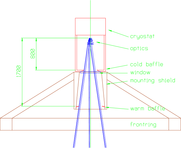
This radiation can be reduced in a prime focus design by placing a cold annular baffle between the detector and primary mirror (Fig. 1). The further this baffle is from the detector (and the nearer it is to the pupil), the smaller is the solid angle subtended by warm surfaces at the detector. The ideal place for the baffle is at the primary mirror, but a cold baffle of 3.5m radius is not feasible! The only practical place is therefore inside the detector dewar, and its maximum distance from the detector is set by one or more of the following:
-
1.
not vignetting the beam reaching the primary mirror from the sky,
-
2.
the optical quality, mechanical stability and availability of the large dewar window,
-
3.
the cost of and heat load on the increasingly larger dewar.
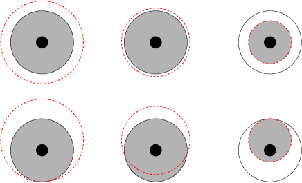
Typically one would use a baffle which is just large enough so as not to obstruct the view of the primary mirror from any point on the detector. This condition we call critical vignetting. Note that the larger the field-of-view, the larger this baffle must be in order to not vignet, and so the larger the solid angle of warm floor/dome which can be seen. This puts a sensitivity penalty on large pixel scales at prime focus. As the baffle is decreased in radius from its critically vignetting size, the floor/dome solid angle is reduced but at the expense of vignetting the light from the primary mirror (Fig. 2). Note that the amount of primary mirror which can be seen by a given pixel depends on the location of that pixel on the detector. This gives rise to differential vignetting across the field of view. As the baffle is made smaller still, there comes a point at which no floor/dome can be seen from any point on the detector and there is nothing gained in reducing the baffle radius further. This condition we refer to as super vignetting, and has the advantage of uniform vignetting across the whole field of view.
We have done some simulations to see how the sensitivity of an instrument on the 3.5m varies between these two extreme vignetting conditions. With a 0.45pix prime focus camera and a cold baffle fixed 0.8m from the detector, its inner radius is varied between 160mm (critical vignetting) and 82mm (super vignetting). The calculation assumes that the background is due to thermal radiation from the primary mirror (r=1.75m, =0.06) and its central hole (r=0.325m, =1.0), and the signal is proportional to the area of the primary which can be seen (minus its hole). Sources are assumed to be black bodies at ambient temperatures. The cold baffle is in the dewar so contributes negligible radiation. Radiation from the primary support structure has also been neglected. We further assume that OH emission from the sky contributes an equal111This is what is expected in summer. In winter the thermal radiation from the optical surfaces in a perfectly baffled camera only accounts for about 20% of the total background, the rest being sky OH emission. Thus in winter the performance of the prime focus camera relative to a Cassegrain focus one will be better than that shown here. amount of background radiation as the thermal emission from the primary mirror (McCaughran et al., unpublished). Thermal emission from the sky at these wavelengths is negligible compared to the OH emission. Fig. 3 shows how the sensitivity of the instrument relative to a perfectly baffled Cassegrain focus camera changes with baffle size. This perfect camera has only thermal emission from the primary mirror and hole, plus thermal emission from an exact-sized secondary mirror with an assumed emissivity of 0.03. As a reimaging Cassegrain focus camera would have several more lenses, it would have a slightly lower throughput, so the sensitivities of the prime focus systems relative to this are slightly conservative.
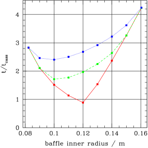
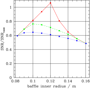
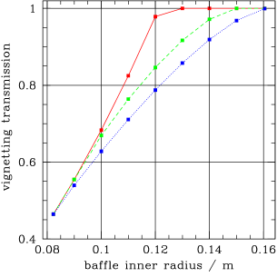
These simulations show that the prime focus camera is almost always less sensitive than a perfectly baffled Cassegrain focus camera in the K band. Interestingly, however, the performance of the prime focus camera is improved (sometimes considerably) by using an undersized baffle. The optimum baffling radius is different for different points on the detector, because the projection of the baffle onto the primary mirror is different for each detector point.
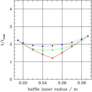
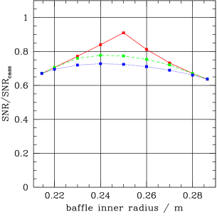
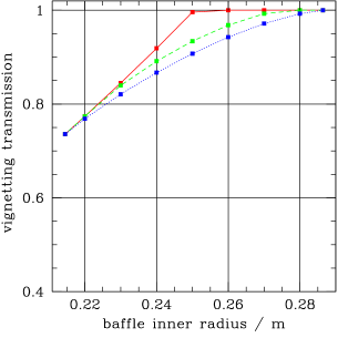
The situation can be improved by adding a warm baffle further away from the detector. The ideal case would be to put a 3.5m diameter high reflectivity ring around the primary mirror which looks through the dome slit at the cold sky. But as it would need an outer radius of almost 4.6m, it would be very expensive and highly impractical. Hence the warm baffle must hang as far below the dewar window as is possible without vignetting the beam from the sky, which is about 1.7m for the Calar Alto 3.5m (see section 4.1). As in Omega Prime, the warm baffle is a polished ellipsoidal annulus which looks into the dewar window to avoid collecting radiation from warm surfaces [6]. Gold coating will further lower its emissivity, but we conservatively assume =0.10 here. Fig. 4 shows how the sensitivity varies as we change the size of this baffle. Note that a critically vignetting cold baffle is also included to reduce the amount of the warm baffle seen by the detector. Because the warm baffle is further from the detector, the variation in sensitivity both for different pixel positions and baffle sizes is less than in Fig. 3. Moreover, the sensitivity relative to the perfect Cassegrain focus camera is better. Uniform sensitivity across the whole field-of-view is usually desirable for a survey instrument, so in practice the super vignetting case may be preferred to intermediate vignetting.
| pixel scale | cold baffle | vignetting mode | vignetting | t/tcass | SNR/SNRcass | |
|---|---|---|---|---|---|---|
| distance | transmission | |||||
| 0.45pix | 0.8m | cold | critical | 1.00 | 4.24 | 0.49 |
| 0.45pix | 0.8m | cold | super | 0.46 | 2.84 | 0.59 |
| 0.45pix | 0.8m | warm | critical | 1.00 | 2.46 | 0.64 |
| 0.45pix | 0.8m | warm | super | 0.74 | 2.23 | 0.67 |
| 0.45pix | 1.0m | cold | critical | 1.00 | 3.48 | 0.54 |
| 0.45pix | 1.0m | cold | super | 0.56 | 2.09 | 0.69 |
| 0.45pix | 1.0m | warm | critical | 1.00 | 2.39 | 0.65 |
| 0.45pix | 1.0m | warm | super | 0.74 | 2.09 | 0.69 |
| 0.40pix | 0.8m | cold | critical | 1.00 | 3.63 | 0.52 |
| 0.40pix | 0.8m | cold | super | 0.54 | 2.22 | 0.67 |
| 0.40pix | 0.8m | warm | critical | 1.00 | 2.18 | 0.68 |
| 0.40pix | 0.8m | warm | super | 0.78 | 1.89 | 0.73 |
| 0.40pix | 1.0m | cold | critical | 1.00 | 3.01 | 0.58 |
| 0.40pix | 1.0m | cold | super | 0.62 | 1.76 | 0.75 |
| 0.40pix | 1.0m | warm | critical | 1.00 | 2.12 | 0.69 |
| 0.40pix | 1.0m | warm | super | 0.78 | 1.79 | 0.75 |
| 0.40pix | 0.4m | warm∗ | critical | 1.00 | 2.24 | 0.67 |
| 0.40pix | 0.4m | warm∗ | super | 0.76 | 1.93 | 0.72 |
∗ These two cases have been calculated for Omega Prime, which has a 1K detector
with 18.5m pixels and a warm baffle 0.82m from the detector.
As mentioned earlier, a larger field of view requires a larger baffle for any given vignetting mode, and therefore a reduced camera sensitivity. To get a quantitative idea of this, we repeated the above calculations for the super and critical vignetting modes but for two different pixel scales, 0.40pix and 0.45pix, and with baffles at various distances. The results are shown in Table 3 and indicate that for a given pixel scale and baffle distances, super vignetting provides better sensitivity than critical vignetting. Having the cold baffle 1.0m rather than 0.8m from the detector gives only a relatively small improvement, and the extra demands this places on the system (e.g. larger dewar window) are probably not worth it. When super vignetting with the warm baffle, the 0.40pix camera is 1.18 times faster for a single shot than the 0.45pix camera. However the 0.45pix scale covers a large area 1.27 times faster, with the net result that the 0.45pix scale is slightly faster for K band surveys. Of course, in the J and H bands super vignetting should never be used, so implementation of super vignetting requires a baffle which can be rapidly (and automatically) moved. Note that the 0.45pix camera in super vignetting mode should have the same K band sensitivity as the current Omega Prime camera (which has a critically vignetting warm baffle). Interestingly, Omega Prime camera should be about 15% faster if it had a super vignetting warm baffle. Such a baffle has been made, but attempts to test it on the telescope have so far been foiled by bad weather.
The 0.45pix camera is still 2.2 times slower than a perfectly baffled Cassegrain focus camera. However, as a pixel scale of only about 0.35pix with good optical quality could be achieved at Cassegrain focus, the survey speed of the perfect Cassegrain focus camera is only about 1.3 times faster in K, and 1.7 times slower in J and H. It should be emphasised that these figures are rather sensitive to the assumptions laid out above, in particular with regard to the emissivity of the optical surfaces and the fraction of OH emission from the sky. Lowering the emissivity or temperature of the warm baffle in particular leads to much better sensitivity.
A three-mirror Cassegrain focus camera similar to that which will be used by WFCAM on UKIRT (3.8m f/2.5 primary) would be possible for the 3.5m at Calar Alto. However, although the current WFCAM design has a cold Lyot stop, it has a vignetting transmission of 73% in all wavebands (WFCAM web pages, ATC, Edinburgh). This is very similar to the K band transmission of Omega 2000 when using the super vignetting warm baffle. Additionally, WFCAM has a center-to-corner distortion of 0.5%, or 42 pixels. However, the super vignetting Omega 2000 design does not appear to be extendible to the much larger field-of-view obtainable with WFCAM.
4 OMEGA 2000 DESIGN
4.1 Optical Design
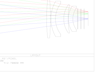
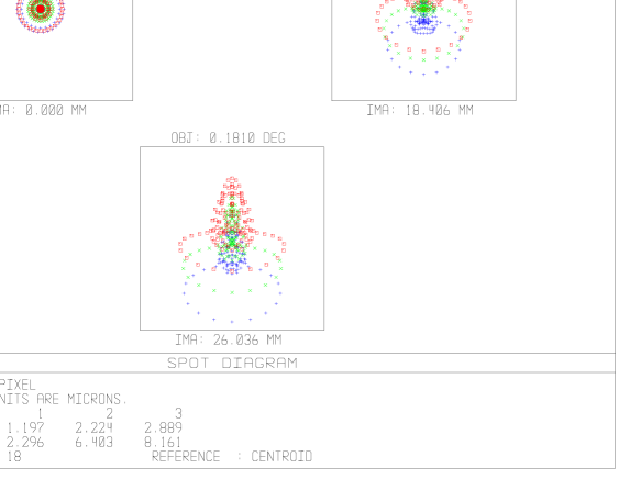
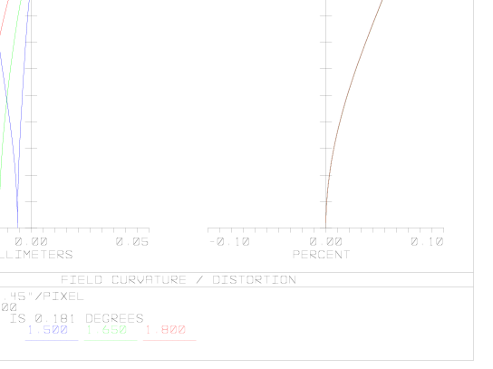
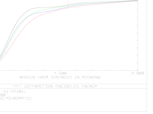
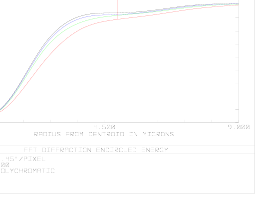
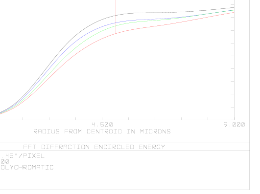
Following all of the considerations described in section 3.1, we decided to place Omega 2000 at the prime focus of the 3.5m telescope with a 0.45pix scale. The optical system consists of four lenses (Fig. 5) and has excellent optical quality (Figs. 6, 7 and 8). Three filter wheels are envisaged, each with slots for six 3 inch (7.6cm) diameter filters. The parameters for the system are given in Table 4.
| primary mirror diameter | 3.5m |
| primary mirror hole diameter | 0.65m |
| primary mirror focal ratio | 3.5 |
| focal station | prime |
| no. of lenses | 4 (cold) |
| no. of optical surfaces | 13 (2 warm) |
| pixel scale | 0.45pix |
| final focal ratio | 2.35 |
| field size | (236 sq. arcmin) |
| dewar window radius | 175mm |
| cold baffle–detector distance | 0.8m |
| cold baffle inner radius | 160mm |
| warm baffle–detector distance | 1.7m |
| warm baffle inner radius | 286mm |
The very low distortion of 0.06% is less than 1 pixel center-to-corner, permitting images to be overlaid with a simple x,y shift. As demonstrated in the previous section, the sensitivity will be very similar to Omega Prime: with a two minute integration in 1′′ seeing, the central pixel of a point source is 5 above the background noise at limits of J=19.2, H=18.1 and K’=17.5 magnitudes [6]. This compares with a mean sky brightness of approximately J=15.2, H=13.6 and K’=13.0 (MAGIC instrument web pages, Calar Alto).
4.2 Mechanical Design
All of the optics will be enclosed in a dewar cooled with liquid nitrogen. The design will be similar to that of Omega Prime [6] with two nested tanks to ensure a stable temperature of 77 K. The optimal baffling was discussed in section 3.2. A fixed critically vignetting cold baffle is on the inside of the dewar window. The window has a radius of 350mm. The cylindrical dewar will be about 0.6m in diameter and between 1.5m and 2.0m long: the exact figure will depend on the final cryogenic design. The heat load on the dewar is large, approximately 300W. A second warm baffle shaped as an oblate ellipsoid sits 1.1m from the dewar window (i.e. 1.7m from the detector). This distance corresponds with the bottom of the existing light shield attached to the bottom of the front ring. This shield actually slightly vignets the beam from the sky, but as it is required for other instruments it cannot be removed. Although the exact design has not yet been worked out, the warm baffle will be moveable between the critical and super vignetting modes (or may consist of two separate baffles). The former mode will be used for the J and H bands, and the latter for the K band. The projection of the super vignetting baffle onto the primary mirror (as seen from the detector) has a diameter of 3.0m, so does not threaten to diffraction limit the instrument at the longest wavelength (2.5m).
4.3 Electronics and Readout Modes
A general readout electronic system is being developed in house. This will be used for a number of different instruments currently under development at MPIA, including Omega 2000 and the MIDI interferometer for the VLT. Only small modifications are required for different detector types.
The HAWAII-2 detector works either with 1 signal channels per quadrant or with 8 signal channels per quadrant simultaneously. All four quadrants can be operated in parallel. The pixels can be clocked at up to 1 MHz which will deliver 1 Megapixels per second per signal channel, with each pixel represented as 16 bits. The minimum integration time is given by the frame readout time, which is the normal state for arrays with integrate-while-read working mode. When working with all 32 channels, the data rate will be 64 Mbyte/sec and the full frame rate is about 8Hz. With only 4 channels (1 per quadrant) the data rate is 4 Mbyte/sec and the full frame rate is about 1Hz.
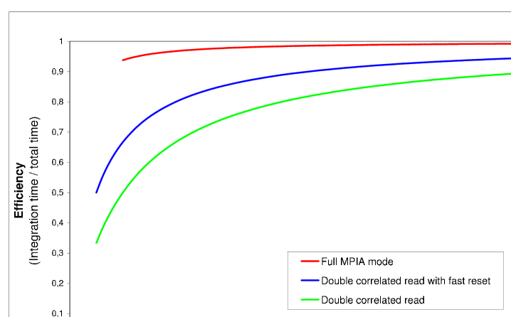
The background limit will be reached in broadband imaging with the HAWAII-2 array on Omega 2000 in a few seconds. Many images (“repeats”) are therefore required to achieve sufficient SNR, so it is very important that the array can be read out quickly with minimum dead time. It is also not necessary to use readout modes which greatly reduce the read noise. There are three different double correlated readout (DCR) modes suitable for detectors with non-destructive readout modes, such as the HAWAII detectors, and each give very different readout efficiencies:
-
1.
Double correlated read. This is the most conservative mode, in that it passes throught the whole array three times to achieve a single image. The first time the whole array is reset, in the second the whole array is read to determine the pixel bias (offset) values, and finally the third read measures the integrated (light-exposed) values. The difference between the integrated and bias values for each pixel is the signal. At minimum integration time the efficiency (as measured by the ratio of integration time to total cycle time required to achieve an image) is 33%. To achieve an integration time longer than the minumum, there is a pause after the second reading of the whole array.
-
2.
Double correlated read with fast reset. This is the current standard readout mode for MPIA instruments. In this mode the whole array must be clocked twice to achieve a single image. First, the whole array is clocked line by line, in which a fast reset is applied to the line followed immediately by a read of that line to determine the pixel biases. Then the whole array is clocked line by line a second time at the same speed as the first array clocking to read the integrated pixel values. The efficiency is 50% for the minimum integration time.
-
3.
Full MPIA mode. The problem with the previous mode is that as soon as the array has been clocked the second time to read the integrated pixel values, those pixels continue to integrate: they are only reset once the first clocking (reset-read) of the next cycle is started. Full MPIA improves upon this by having only a single type of pass through the whole array. The array is clocked line by line starting with a read of the integrated pixels of a line, followed by a fast reset of that line, and then a read of the pixel bias values of that line. These bias values are those which will be subtracted from the integrated pixel values obtained the next time the whole array is read. Once the whole array has been read, there is a pause (if the integration time is above the minimum) and the cycle repeated for as many images (“repeats”) as required. Essentially no time is now wasted, and for any integration time the efficiency of this mode is almost 100%.
Whereas the first mode is a completely array-oriented approach, the full MPIA mode is a completely line-oriented approach. DCR with fast reset is essentially a mix of the two. Full MPIA mode is more efficient because each line is reset and the bias values read immediately after reading the integrated pixel values: DCR mode with fast reset waits until the whole array has been read before reseting. To obtain just a single image, DCR with fast reset takes the same time as full MPIA mode, but for a sequence of many repeats, full MPIA mode is much quicker (Table 5). The relative speeds for different integration times of the three modes has been empirically determined at MPIA using HAWAII arrays (Fig. 9). Note that the minimum integration time with full MPIA mode is twice that of DCR mode with fast reset (0.25 rather than 0.125s for the HAWAII-2), but this is not a problem for Omega 2000.
| Full MPIA mode | DCR with fast reset | |
|---|---|---|
| (read-reset-read) | (reset-read.read) | |
| Minimum integration time | 0.262s | 0.131s |
| Correlated image frequency | 4Hz | 4Hz |
| Single image efficiency | 50% | 50% |
| Stack of 10 images efficiency | 91% | 50% |
| Time for 60s integration | 60.262s | 90.00s |
| (0.262s integration per frame) |
4.4 Data Acquisition and Control Software
The MPIAs GEneric InfraRed camera Software (GEIRS) [6] will also be used for Omega 2000. The new challenge is the 26 times higher data rate compared to the 1K1K HAWAII detector on existing instruments. The data acquisition software must be able to sustain this data rate continuously, apply necessary preprocessing tasks, have data visualization control and save the data in time to non-volatile storage disks. The data are acquired by either one or two 30 MHz 16bit parallel interfaces.
The handling of the increased data rate can only be organised in a current state of the art symmetrical multiprocessor system (e.g. a SPARC Ultraserver 450), where nearly the full memory bandwidth is consumed for the basic tasks needed to control the camera system and human interfacing. The software package is already optimised for minimal usage of memory by sharing data memory between all processes. To keep the jobs synchronised without loss of efficiency, further parallelization making optimal use of the multiprocessing capabilities has to be implemented. The granularity of the shared memory buffers for the parallel processing also has to be reorganised to make more efficient use of the increased internal working memory. Although this can be done with standard computer architecture, there remains the option of using distributed processing on standard hardware with distributed memory (the so-called “multiple instructions on multiple data” organization).
References
- [1] Herbst T.M., Thompson D., Fockenbrock R., Rix H.-W., Beckwith S.V.W., “Constraints on the space density of methane dwarfs and the substellar mass function from a deep near-infrared survey”, ApJ 526, L17, 1999
- [2] Kozlowski L.J. et al. “HgCdTe 20482 FPA for infrared astronomy: development status”, in Infrared astronomical instrumentation, A.M. Fowler ed., Proc. SPIE 3354, pp. 66–77, 1998
- [3] Fruchter A.S., Hook R.N., Busko I.C., Mutchler M., “A package for the reduction of dithered undersampled images”, in 1997 HST Calibration Workshop, pp. 518, S. Casertano et al. eds., Baltimore: Space Telescope Science Institute, 1997
- [4] Papoular R., “The processing of infrared sky noise by chopping, nodding and filtering”, A&A 117, 46, 1983
- [5] Ramsay S.K., Montain C.M., Geballe T.R., “Non-thermal emission in the atmosphere above Manua Kea”, MNRAS 259, 751, 1992
- [6] Bizenberger P., McCaughrean M., Birk C., Thompson D., Storz C., “Omega Prime: The wide-field near-infrared camera for the 3.5m telescope of the Calar Alto observatory”, in Infrared Detectors and Instrumentation, A.M. Fowler ed., Proc. SPIE 3354, pp. 825–832, 1998