On the optical pulsations from the Geminga pulsar
Abstract
We present a model for generation mechanisms of the optical pulsations recently detected from the Geminga pulsar. We argue that this is just a synchrotron radiation emitted along open magnetic field lines at altitudes of a few light cylinder radii (which requires that Geminga is an almost aligned rotator), where charged particles acquire non-zero pitch-angles as a result of the cyclotron absorption of radio waves in the magnetized pair plasma (Gil, Khechinashvili & Melikidze 1998, hereafter Paper I). This explains self-consistently both the lack of apparent radio emission, at least at frequencies higher than about 100 MHz, and the optical pulsations from the Geminga pulsar. From our model it follows that the synchrotron radiation is a maximum in the infrared band, which suggests that Geminga should also be a source of a pulsed infrared emission.
keywords:
pulsars: individual: Geminga – optical emission1 Introduction
An optical counterpart of the Geminga source was found by Bignami et al. (1987), based upon color considerations. Recent spectral studies (Martin et al. 1998) show a continuous power-law from 3700 to 8000 Å with a broad absorption feature over Å band. Such a spectrum indicates existence of the dominant nonthermal synchrotron component in the optical emission of the Geminga pulsar.
Recently Shearer et al. (1998), based on their deep integrated images in -band, claimed that the optical counterpart of Geminga pulses with a period ms, reported also at (Halpern & Holt 1992) and -ray (Bertch et al. 1992) bands. They derived the magnitude of the pulsed emission mag, and found that the signal shows two peaks with a phase separation of . It appeared that there is a phase agreement of the optical data with and hard -ray curves. Moreover, the form of the optical light curve resembles that of and hard -rays rather than the soft -rays signature. According to Shearer et al. (1998), this is a further evidence of the predominantly magnetospheric origin of Geminga’s pulsed optical emission (Halpern et al. 1996) over a thermal one (Bignami et al. 1996).
We suggest that Geminga’s pulsed optical emission is a synchrotron radiation of the plasma particles gyrating about relatively weak magnetic field of the distant magnetosphere of this pulsar. As we demonstrate below, the plasma particles acquire perpendicular momenta, necessary for the synchrotron emission, due to cyclotron absorption of radio waves on these particles. There is an evidence that the Geminga pulsar is either radio quiet or, more likely, visible only at low radio frequencies below about MHz (e.g. Malofeev & Malov 1997; Vats et al. 1999; see also Paper I).
2 Estimation of pitch-angles
Mikhailovskii et al. (1982) were first to suggest that the energy lost by radio waves due to cyclotron damping should lead to ’heating’ of the ambient plasma, i.e. increase of its perpendicular temperature. Lyubarskii & Petrova (1998) treated thoroughly spontaneous re-emission of the absorbed energy, and concluded that in short-period pulsars a significant fraction of this energy is re-emitted in the far infrared band. They found that an electron (or positron), moving initially with the relativistic velocity strictly along the local magnetic field, obtains a pitch-angle111The pitch-angle is defined as , where and are the components of the particle momentum along and across the local magnetic field, respectively.
| (1) |
in the course of cyclotron absorption of radio emission. Here is an angle between the wave vector and the local magnetic field , and
| (2) |
is the ratio of the radio luminosity to the particle luminosity, that is, the ratio of the power of radio waves (damped due to cyclotron resonance) to the total kinetic energy of the resonant particles produced per second above a fraction of the polar cap with the area (see equation 4). Note that equation (1) is valid provided that . Estimation of is presented below.
The radio luminosity of the Geminga pulsar, by what we mean the integrated radio power of Geminga as it would be in the absence of cyclotron damping on the magnetospheric plasma (Paper I), can be estimated as
| (3) |
where (Vats et al. 1999), GHz is a frequency range where the bulk of pulsar radio emission is usually radiated, and cm is a distance to the Geminga pulsar. Inserting all these values into equation (3) we find that .
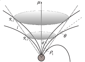
Let us now evaluate the denominator in equation (2). According to Paper I (see also Malov 1998), the Geminga pulsar is an almost aligned rotator, and for the inclination angle and the impact angle , an observer’s line of sight in fact grazes the emission cone radiated from the bundle of the last open field lines, with the opening angle at about 100 MHz being (Khechinashvili, Melikidze & Gil 1999). The latter defines a group of the radial lines constituting an angle with the magnetic axis (see Fig. 1). The simulation of radio waves damping along these lines (Paper I; Khechinashvili et al. 1999) shows that MHz radio waves are damped at the distance , whereas GHz waves are damped at . Here is a distance from the star’s centre measured in the units of the light cylinder radius (). One can speculate that the major part of Geminga’s radio emission is effectively damped within a cut-cone-shaped volume represented in Fig. 1. Then, let us consider the dipolar field line which crosses the radial line, constituting the angle with , at the distance . The footprint of this field line on the stellar surface has a polar angle rad. The footprints of all inner field lines, on which GHz radio frequencies are damped at high altitudes (see above), mark a circle with the angular radius within the pulsar polar cap through which the resonant leave the neutron star. Let us notice that , where is an angular radius of the pulsar polar cap, and cm is a stellar radius. Hence, only a fraction of the polar cap provide resonant particles. The area of this region is
| (4) |
which yields
| (5) |
Here the surface value of the corotational charge number density (Goldereich & Julian 1969) was substituted, which was evaluated for the dynamical parameters of the Geminga pulsar ( s and ); is the Sturrock multiplication factor (Sturrock 1971). Evaluating equation (5) we assumed that the mean Lorentz factor of the ambient plasma particles . From equation (5) it follows that
| (6) |
particles are generated per second over the area of (equation 4).
Substituting the derived values and in equation (2) we obtain that . Then, taking into account the average value of the angle rad (Khechinashvili et al. 1999) in equation (1), we find that the characteristic pitch-angle of plasma particles is rad. Therefore, a ’kick’ that each electron gets due to the cyclotron absorption of radio waves, depends on the number of particles (determined by the Sturrock multiplication factor ) among which the energy of these waves is distributed. For example, inside the spark-associated columns of plasma (e.g. Ruderman & Sutherland 1975; Gil & Sendyk 1999), where , we have . At the same time, in the regions of reduced number density between the spark-associated columns of plasma, where we obtain For the particle to emit the synchrotron radiation the condition
| (7) |
should be satisfied. Apparently, the latter condition is not met inside the dense plasma ( for ), whereas in the space of reduced number density it is satisfied well. In other words, only the particles, being in the space between the spark-associated plasma columns, obtain (due to cyclotron absorption of radio waves) pitch-angles big enough to start gyrating relativistically, hence, emitting synchrotron radiation.
3 The synchrotron model
The total radiated power of a single electron synchrotron radiation is defined as (Ginzburg 1979; Lang 1980)
| (8) |
and the critical frequency of the synchrotron radiation is
| (9) |
The spectral density of a single electron radiation power near is
| (10) |
Let us notice that, if a source as a whole is moving towards an observer, the power given by equation (8) should be divided by (see equation (5.12) in Ginzburg (1979) and the discussion on page 75). However, this is not the case in our current application, as the emitting volume represented in Fig. 1 is quasi-stationary with respect to an observer on Earth. Indeed, the particles are permanently flowing in and out but the volume as the whole does not approach an observer with the relativistic velocity. That is why the multiplier should be omitted in this consideration.
The average magnetic field in the region where synchrotron emission is generated (Fig. 1) can be estimated from the equation
| (11) |
as G. This provides the critical frequency Hz (equation 9), which falls into infrared band (the frequency corresponding to the maximum in the single electron synchrotron spectrum yields Hz). From equation (10) we find that It is natural to assume that the spectral density of total power radiated by electrons is
| (12) |
Let us then estimate , i.e., the total number of emitting particles. From Fig. 1, assuming the conservation of the particle flux along the dipolar fields lines, we find that in the cut-cone with the height cm there are particles (where is defined from equation 6) at any given moment of time. Then, from equation (12), for , we obtain
| (13) |
which is a theoretical value of spectral density near the critical infrared frequency . The spectral density of power in the -band can be deduced using the power-law spectrum of Geminga’s optical emission (Martin et al. 1998), as
| (14) |
where Hz.
Let us compare the theoretical value of (equation 14) with that provided by the observations. The latter can be derived from the spectral density of flux cm-2 (see Fig. 3 in Martin et al. 1998), which gives the spectral density of total power
| (15) |
where is a beaming factor and cm. According to Fig. 1, using the features of the dipolar geometry, we find that rad, which leads to the beaming factor sr (instead of sr for the isotropic radiation). Therefore, equation (15) yields , which is consistent with our theoretical prediction (equation 14).
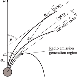
Obviously, the fraction of the synchrotron optical radiation of Geminga observed on Earth is emitted in the same direction as the low-frequency radio waves (Paper I). Using the feature of dipolar field lines that all of them intersect any given radial line with the same angle, we find a geometrical place of all the points in the magnetosphere where the tangents to the field lines point to the same direction222 at the nearest approach of the line of sight to the magnetic axis , and at the furthest one. as a wavevector of the 100 MHz radio waves. As it is seen in Fig. 2, these points are placed at the radial straight lines inclined to at an angle from the side of the nearest approach to and from the furthest one. The ’optically bright’ region is restricted in the longitudinal direction to the altitudes along these lines, where the cyclotron damping of GHz radio waves occurs. Calculations show (Khechinashvili et al. 1999) that the longitudinal size of this region . The dimension of this region in the transverse direction can be estimated as , where is a magnetic field line curvature at corresponding altitude. Such an estimation of assumes that this is a characteristic distance at which a particle moving along the curved magnetic field line keeps emitting towards the observer (i.e., an observer stays in the emission diagram of a singel particle, within the angle range ). The corresponding characteristic time is , during which a particle radiates energy. Obviously, the latter should be much less than the kinetic energy of an electron . Let us notice that in such a consideration the multiplier (see the discussion below equation 10) should be taken into account in equation (8), as the source of the synchrotron radiation (a particle) is moving towards the observer in this case. Using equation (8) with the latter correction we find that so that only a tiny fraction of the particle’s kinetic energy is radiated away as a synchrotron emission. Assuming that this is valid for all the radiating particles, we can estimate the total radiated power of the synchrotron radiation as (where is found from equation 5). Then, using equation (10), we obtain . We see that this value is consistent with our previous theoretical estimation (equation 13), and hence with the observationally derived value (equation 15). The consideration based on the energy conservation provides an independent test of our model.
In the calculations above we assume that both pitch-angles and Lorentz factors of emitting particles remain constant while the particles cross the ’optically bright’ region. Obviously, this assumption is valid for Lorentz factors because . As for pitch-angles, it requires that a single particle goes through at least few acts of radio-absorption during the time s. This is equivalent to fulfillment of the following condition
| (16) |
Here is a characteristic time-scale of the cyclotron damping, and is the damping decrement. We found (Paper I; Khechinashvili et al. 1999) that at the distances where the bulk of radio band ( GHz) is typically damped. Therefore, and . Thus, the parameters and used in our model can be considered quasi-stationary.
We believe that the apparent optical spectral index (Martin et al. 1998) indicates a power-law distribution of emitting particles over energy , where (Ginzburg 1979; Lang 1980). Such a distribution function can be expected in the region where the synchrotron optical radiation of the Geminga pulsar is believed to originate.
4 Conclusions
The model for the optical radiation of the Geminga pulsar, presented in this paper, is a direct consequence of our model for its erratic radio emission (Paper I). Let us summarise our main results: (i) Relativistic charged particles of the pulsar magnetosphere obtain non-zero pitch-angles due to cyclotron damping of radio waves; (ii) The particles re-emit the absorbed radio energy in the form of synchrotron radiation, with a maximum power in the infrared band; (iii) The observed optical emission of the Geminga pulsar is just a short-wavelength continuation of its power-law synchrotron spectrum; (iv) The optical power estimated from our model, using two different approaches, agrees with the observed value; (v) We predict a significant pulsed infrared emission which should be observed from the Geminga pulsar; (vi) As a by-result, we support a model of the non-uniform plasma outflow in pulsar magnetospheres, originating in the form of spark discharges above the polar cap.
5 Acknowledgments
The work is supported in parts by the KBN Grants 2 P03D 015 12 and 2 P03D 003 15 of the Polish State Committee for Scientific Research. G. M. and D. K. acknowledge also support from the INTAS Grant 96-0154.
References
- [Bertch et al.(1992)] Bertsch D. L. et al., 1992, Nature, 357, 306
- [Bignami et al.(1987)] Bignami G. F., Caraveo P. A., Paul,J. A., Salotti L., Vigroux L., 1987, ApJ, 319, 358
- [Bignami et al.(1996)] Bignami G. F., Caraveo P. A., Miganni R., Edelstein J., Bowyer S., 1996, ApJ, 456, L111
- [Gil & Sendyk(1999)] Gil J., Sendyk M., 1999, ApJ, in press
- [Gil et al.(1998)] Gil J. A., Khechinashvili D. G., Melikidze G. I., 1998, MNRAS, 298, 1207 (Paper I)
- [Ginzburg(1979)] Ginzburg V. L., 1979, Theoretical Physics and Astrophysics. Int. Series in Natural Philosophy, vol. 99, Pergamon, Oxford
- [Goldreich & Julian(1969)] Goldreich P., Julian W. H., 1969, ApJ, 157, 869
- [Halpern & Holt(1992)] Halpern J. P., Holt S. S., 1992, Nature, 357, 222
- [Halpern et al.(1996)] Halpern J. P., Martin C., Marshall H. L., 1996, ApJ, 473, L37
- [Khechinashvili et al.(1999)] Khechinashvili D., Melikidze G., Gil J., 1999, in preparation
- [Lang(1980)] Lang K. R., 1980, Astrophysical Formulae. Springer, New York
- [Lyubarskii & Petrova(1998)] Lyubarskii Y. E., Petrova S. A., 1998, A&A, 337, 433
- [Malofeev & Malov(1997)] Malofeev V. M., Malov O. I., 1997, Nature, 389, 697
- [Malov(1998)] Malov I. F., 1998, Astron. Reports, 42, 246
- [Martin et al.(1998)] Martin C., Halpern J. P., Schiminovich D., 1998, ApJ, 494, L211
- [Mikhailovskii et al.(1982)] Mikhailovskii A. B., Onishchenko O. G., Suramlishvili G. I., Sharapov S. E., Sov. Astron. J. Letters, 8, no.11, 685
- [Ruderman & Sutherland(1975)] Ruderman M. A., Sutherland P. G., 1975, ApJ, 196, 51
- [Shearer et al.(1998)] Shearer A. et al., 1998, A&A, 355, L21
- [Sturrock(1971)(1971)] Sturrock P. A., 1971, ApJ, 411, 674
- [Vats et al.(1999)] Vats H. O., Singal A. K., Deshpande M. P., Iyer K. N., Oza R., Shah C. R., Doshi S., 1999, MNRAS, 302, L65