Design of the Muon Collider Lattice: Present Status
Abstract
We discuss a preliminary design for a high luminosity 4 TeV center of mass collider ring.
1 INTRODUCTION
The last component of a muon collider facility, as presently envisioned[1], is a colliding-beam storage ring. Design studies on various problems for this ring have been in progress over the past year[2]. In this paper we discuss the current status of the design.
The projected muon currents require very low beta values at the IP, in order to achieve the design luminosity of The beta values in the final-focus quadrupoles are roughly To cancel the corresponding chromaticities, sextupole schemes for local correction have been included in the optics of the experimental insertion[3]. The hour-glass effect constraints the bunch length to be comparable to To obtain such short bunches with reasonable rf voltage requires a very small value of the momentum compaction which can be obtained by using flexible momentum compaction (FMC) modules in the arcs[4].
A preliminary design of a complete collider ring has now been made; it uses an experimental insertion and arc modules as described in refs.[2]-[4] as well as a utility insertion. The layout of this ring is shown schematically in Fig.1,
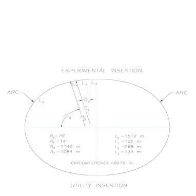
and its parameters are summarized in Tb.1.
| Maximum c-of-m Energy [TeV] | 4 |
| Luminosity [cm-2s-1] | 1.0 |
| Circumference [km] | 8.08 |
| Time Between Collisions [s] | 12 |
| Energy Spread [units ] | 2 |
| Pulse length [mm] | 3 |
| Free space at the IP [m] | 6.25 |
| Luminosity life time [No.turns] | 900 |
| rms emittance, [m-rad] | 50.0 |
| rms emittance, [m-rad] | 0.0026 |
| Beta Function at IP, [mm] | 3 |
| rms Beam size at IP [m] | 2.8 |
| Quadrupole pole fields near IP [T] | 6.0 |
| Maximum Beta Function, [km] | 400 |
| Magnet Aperture closest IP [cm] | 12 |
| Beam-Beam tune shift per crossing | 0.04 |
| Repetition Rate [Hz] | 15 |
| rf frequency [GHz] | 3 |
| rf voltage [MeV] | 1500 |
| Particles per Bunch [units ] | 2 |
| No. of Bunches of each sign | 2 |
| Peak current [kA] | 12.8 |
| Average current [A] | 0.032 |
| Horizontal tune | 55.79 |
| Vertical tune | 38.82 |
Though some engineering features are unrealistic, and the beam performance needs some improvement, we believe that this study can serve as the basis for a workable collider design.
The remaining sections of the paper will describe the lattice, show beam behaviour, and discuss future design studies.
2 LATTICE
2.1 Global structure
The ring has an oval shape, with reflection symmetry about two perpendicular axes, see Fig. 1. The lattice has two nearly circular arcs joined by the experimental and utility insertions. Each insertion contains two bending sections.
The two arcs are identical; each contains 22 periodic modules and two dispersion suppressor modules. The two insertions are geometrically identical, and each is symmetric about its center. Each half insertion has three parts: two straight sections separated by a bending section. The bending sections are identical in the experimental and utility insertions, except for sextupole strengths; the straight parts have different quadrupole lengths and gradients. Thus, the focusing structure of the ring has one superperiod, with reflection symmetry about the line joining the centers of the two insertions.
2.2 Arc module
In order to have very short bunches in the 2 TeV muon collider, the storage ring must be quasi-isochronous, which requires that the momentum compaction be very close to zero, where is defined in terms of offsets of the momentum and equilibrium orbit circumference by
| (1) |
which may be shown to be equal to
| (2) |
where is the dispersion function, the radius of curvature and is the longitudinal path length measured along the closed orbit. Since there is a closed orbit for every value of the momentum, all of these quantities including are functions of .
The particle motion in longitudinal phase space depends on changes of its arrival time at the rf cavities, which depends on changes of circumference and velocity . To first order the time difference is: and is related to the change in momentum by where is the time of arrival of the reference particle; and are the time and momentum deviations, respectively, of the off-momentum particle relative to the synchronous particle with momentum ; is the phase slip factor; is the relativistic energy, and The transition energy is defined by .

In an isochronous ring , so to first order the arrival time is independent of the momentum; the condition for which is . For 2 TeV muons so In a regular FODO lattice, is much larger. To bring the first order value of to zero requires that through all of the dipoles be equal to zero.
In a FODO lattice is positive. This muon collider ring design has bending regions in the insertions with a FODO structure whose contributions to are positive, so the contributions of the arcs must be negative with nearly the same magnitude as those of the insertions. For the present design, the value needed for each arc is
This value of can be obtained by building an arc whose periods are FMC modules. An FMC module[4] is a symmetric structure composed of two FODO cells separated by a matching insertion which transforms to
The contribution to of the module can be adjusted by choosing the appropriate value of (with ) at the end of the module. For the module design used here (see Fig.2), the matching insertion contains two quadrupole doublets and two dipoles. The two quadrupole gradients and drift lengths are adjusted to bring and to zero at the center of the module. The number of modules and the bending angles of the dipoles are chosen to give the entire arc the bending angle of needed to close the ring.
The arc modules also contain sextupoles; there are two families adjusted to bring the chromaticities of the arc to zero. Alternatively, they could be used to control the quadratic dependence of , as is discussed in section 4.1.
The parameters of the arc modules are given in Tb.2.
| Total length [m] | 126 |
|---|---|
| Total angle [deg.] | 6.53 |
| No. modules per arc | 22 |
| No. dipoles | 10 |
| No. quadrupoles | 7 |
| No. sextupoles | 3 |
| Dipole length [m] | 8 |
| Dipole field [T] | 9.51 |
| Max. gradient [T/m] | 240 |
| Max. sext. strength [T/m2] | 2074 |
| Tune | 0.896 |
| Tune | 0.536 |
| Chromaticity | -1.36 |
| Chromaticity | -0.71 |
| Compaction | |
| Max. [m] | 78 |
| Max. [m] | 78 |
| Max. [m] | 1.52 |
| Min. [m] | -1.73 |
2.3 Dispersion suppressor
A dispersion suppressor module is located at each arc end, which brings the dispersion and its slope to zero in the adjacent insertion straight section.

The suppressor at the arc-end preceding an insertion is shown in Fig.3; the suppressor following an insertion is obtained by reflection. This suppressor module is identical to a regular module except that the first four dipoles have been replaced by two dipoles with normal length and different field values. The lengths, strengths and positions of the quadrupoles and sextupoles are the same as in the regular modules.
The suppressor brings the dispersion and its slope to zero at the end of the arc exactly; however there are small errors in the beta functions. These errors could be removed by changing the gradients of some of the quadrupoles.
The parameters of the dispersion suppressor module are given in Tb.3.
| Total length [m] | 126 |
| Total angle [deg.] | 3.99 |
| No. suppressors per arc | 2 |
| No. normal dipoles | 6 |
| No. special dipoles | 2 |
| No. quadrupoles | 7 |
| No. sextupoles | 3 |
| Dipole length [m] | 8 |
| Field normal dipole [T] | 9.51 |
| Field dipole [T] | 8.72 |
| Field dipole [T] | -7.63 |
| Max. gradient [T/m] | 240 |
| Max. sext. strength [T/m2] | 2074 |
| Tune | 0.896 |
| Tune | 0.536 |
| Chromaticity | -1.36 |
| Chromaticity | -0.71 |
| Compaction | |
| Max. [m] | 80 |
| Max. [m] | 84 |
| Max. [m] | 1.41 |
| Min. [m] | -1.73 |
2.4 Experimental insertion
The design of an insertion with an extremely low-beta interaction region for a muon collider[5] presents a challenge similar to that encountered in the Next Linear Collider (NLC)[6]. The design used here for each half of the symmetric low-beta insertion follows the prescription proposed by Brown[7]; it consists of two telescopes with a chromatic correction section between them. Fig.4 shows the left half of the insertion, starting at the end of the arc dispersion suppressor and ending at the IP.

The first telescope, called the Matching Telescope (MT), on the left of the figure, brings the beta functions from the arc to a focus of about 3 cm. To the right of the MT lies the Chromatic Correction Section (CCS), which contains two pairs of non-interleaved sextupoles. One pair, situated at positions of maximum and large dispersion , corrects horizontal chromaticity; the other pair, at maximum positions, corrects vertical chromaticity. The horizontal-correcting pair is farthest from the IP, and the vertical-correcting pair is closest. The sextupoles of each pair are separated by phase advances of and they are all located at odd multiples of phase intervals from the IP. To the right of the CCS, the Final Focus Telescope (FFT) transports the beta functions from a focus of a few centimeters to a 3 mm focus at the IP.
The low beta-function values at the IP are obtained with four strong quadrupoles in the FFT with high beta values; these generate large chromaticities which are corrected locally with the two sextupole pairs in the CCS. This sextupole arrangement cancels the second-order geometric aberrations of the sextupoles, which reduces the second order tune shift by several orders of magnitude. The momentum bandwidth of the system is limited by third-order aberrations and residual second-order amplitude-dependent tune shifts. These aberrations arise from: a) small phase errors between the sextupoles and the final quadruplet; b) finite length of the sextupoles.
The residual chromaticities could be reduced with additional sextupoles at locations with nonzero dispersion, as suggested by Brinkmann[8]. Finally, a system of octupoles could be designed to correct third-order aberrations. Overall, it is believed possible to construct a system with a bandwidth of
The most complex part of the insertion is the CCS. A somewhat oversimplified description follows. The CCS consists of eight FODO cells, each with phase advances. The first four cells from the left begin at the center of a QF quadrupole and contain the two horizontal sextupoles, which are next to QF’s; the next four cells begin at the center of a QD and contain the vertical sextupoles next to QD’s. The low-beta focus at the beginning of the CCS repeats itself every two cells and produces the high beta values needed in the sextupoles. The dipoles are placed in a way to cancel the dispersion and its slope at the ends of the CCS and to produce dispersion maxima near the sextupoles.
The strengths of the sextupoles and are adjusted to minimize the first order chromaticity, while trim quadrupoles, located at the ends of the fourth and eighth FODO cells, are used to minimize the second order chromaticity The complete insertion has very small residual chromaticity and is nearly transparent when attached to the arc lattice.
The total length of the half insertion is 507 m; it contains 44 quadrupoles, 14 sector dipoles and 4 sextupoles. A few dipoles have excessive fields and there is no space between many of the magnets.

Parameters of the experimental insertion are given in Tb.4.
| Total length [m] | 1014 |
|---|---|
| Total angle [deg.] | 28.3 |
| Mom. compaction | |
| Horizontal tune | 6.41 |
| Vertical tune | 6.56 |
| Max. [km] | 283 |
| Max. [km] | 360 |
| Max. dispersion [m] | 1.04 |
2.5 Utility insertion
The utility insertion closely resembles the experimental insertion, except that the low-beta foci are relaxed in order to lower the beta-function maxima by a factor of about 1000, see Fig.5. This is done by relaxing the focusing in the two telescopes. The CCS section is the same as in the experimental insertion, except that the sextupoles are adjusted to cancel the total chromaticity of the utility insertion. Further changes will probably be needed in the future to better accommodate requirements of injection, RF, and scraping.
3 PERFORMANCE
The variations of the fractional part of the global tunes as functions of are shown in Fig.6.

is essentially flat over a bandwidth of , but has non-linear components, although the variation of tune, peak to peak is less than within a bandwidth of to The next figures show the momentum dependences of (Fig.7), chromaticity (Fig.8), momentum compaction (Fig.9) and of the amplitude dependent tune shifts (Fig.10).


4 IMPROVEMENTS
4.1 Suppression of Spread of Momentum Compaction
Although the collider ring has been adjusted to be isochronous for the reference particle, the off-momentum particle will see a small nonzero momentum-compaction factor, which is defined to be The length of the closed orbit for an off-momentum particle can be expanded as a function of momentum offset , we write where is considered as a single variable. Consequently, the momentum compaction seen by the off-momentum particle is Therefore, for an isochronous ring, there is still a spread of momentum compaction . The first-order momentum compaction is determined by the dispersion function at the dipoles. The second-order momentum compaction, however, in addition to the contribution from the second-order dispersion function at the dipoles, contains an extra wiggling term. This wiggling term, equal to one half the average of the square of the derivative of the dispersion, is a measure of the additional path length due to the closed orbit wiggling in and out of the reference orbit.
For normal FODO cells, the dispersion wiggles between 0.65 m and 1.24 m from the defocusing quadrupole to the focusing quadrupole, for a total of 0.59 m; for a FMC module, the dispersion oscillates between m and m, for a total of 3.25 m. As a result, the wiggling term is expected to be much larger. This eventually leads to a much larger than for a FODO cell. If the chromatic sextupoles at the IR are used to correct the chromaticities of the IR, while the sextupoles in arc modules correct chromaticities of the arc modules, then this isochronous ring has a momentum-compaction factor varying almost linearly with momentum; and at , respectively, for a total spread of this is illustrated in Fig.11. We can also see that is positive.

In order to have the muons remain bunched, a rather huge rf system will be necessary for such a large spread of momentum compaction.
Sextupoles affect . Consider a FODO-cell system with sextupoles of strengths and , respectively, at the focusing and defocusing quadrupoles. The change in second-order momentum compaction[10] is given by where and are the first-order dispersions at the focusing and defocusing quadrupoles. We may expect the behavior to be similar for our arc modules. If both sextupoles are used to compensate for natural chromaticities, the one with will lower while the one with will increase it. Therefore, we should first forget chromaticity correction and use only one sextupole of strength on each side of the lower-beta doublets where and dispersion is large. At this moment, each arc module has been tuned to have in order to maintain isochronocity of the whole ring. By adjusting the sextupole strength to the optimum value of m-2, the momentum compaction of the arc module becomes when the momentum offset is . The variation of is plotted in Fig.12 and looks like a parabola, implying that has been adjusted to zero and what is left is the third-order contribution.

The total swing of is now . From the shape of Fig.11, the momentum-compaction factor of each module should have been adjusted instead to , so that eventually the spread of momentum compaction will become , which is acceptable for a moderate-size rf system.
The introduction of this -correction sextupoles bring the chromaticities (here we denote chromaticity with the symbol ) of each arc module to to and to when the momentum offset varies from t0 , as illustrated in Fig.12. There are 40 arc modules and they contribute therefore chromaticities of and to the whole collider ring. But these chromaticities are only very tiny compared with the units from the IR, and can be removed by making minor adjustment to the chromatic correction sextupoles of the IR. There will still be a spread of chromaticities as a function of momentum due to the arc modules, with a total of and .
If the spread of momentum compaction and the spreads of chromaticities are still too large, we can construct another similar arc module that has a smaller dispersion wiggling. We have a design in Fig.13 that employs quadrupoles with strengths reduced roughly by 1/3 in the FODO regions, but almost doubled in the low-beta region.

This module has a maximum and minimum dispersion of m and m. When its chromaticities are corrected to zero with focusing and defocusing sextupoles, it gives a total spread of equal to only when the momentum offset is , as shown in Fig.14 drawn in the same scale as Fig.12.

If only a pair of sextupoles is used to compensate for as in above, at the optimum sextupole strength of m-2, the spread of momentum compaction will only be , which is about 2.5 times less than the former arc module.

5 CONCLUSIONS
A possible lattice for a muon collider has been described. The design satisfies most of the collider requirements, although it is not fully realistic. Error and tolerance analyses are yet to be performed as well as tracking to determine the dynamic aperture and achievable luminosity.
In order to make the final-focus design realistic, drift spaces must be introduced between all magnet elements, and the lengths of the insertions will have to be increased in order to achieve the required dispersion values in the sextupoles with reasonable dipole fields.
ACKNOWLEDGMENTS
This research was supported by the U.S. Department of Energy under Contract No. DE-ACO2-76-CH00016. (RBP) gratefully acknowledge stimulating discussions with J. Irwin, O. Napoly and K. Oide.
References
- [1] R. Palmer, et al. Muon Collider Design, this Proceedings.
- [2] N.M. Gelfand, A Prototype Lattice Design for a 2 TeV Collider, Fermilab Report TM-1933, 1995; King-Yuen Ng, presentation at the 9th Advanced ICFA Beam Dynamics Workshop: Beam Dynamics and Technology Issues for Colliders, Montauk, New York, Oct 15-20, 1995, to be published; D. Trbojevic, et al., Design of the Muon Collider Isochronous Storage Ring Lattice, submitted to the proceedings of the Micro Bunches Workshop, BNL, Sep. 1995, to be published; C. Johnstone and K.-Y. Ng, Interaction Regions for a Muon Collider , submitted to the proceedings of the Micro Bunches Workshop, BNL, Sep. 1995; to be published.
- [3] Juan C. Gallardo and Robert B. Palmer, Final Focus System for a Muon Collider: A Test Model, this Proceedings.
- [4] S. Y. Lee, K. Y. Ng and D. Trbojevic, Minimizing dispersion in flexible-momentum-compaction lattices, Phys. Rev. E 48, 3040 (1993)
- [5] R. B. Palmer, Beam Dynamics in a Muon Collider Beam Dynamics Newsletter, No.8 (1994) 27, Eds. K. Hirata, S. Y. Lee and F. Willeke.
- [6] F. Zimmermann, et al., A Final Focus System for the Next Linear Collider, SLAC-PUB-95-6789, June 1995, presented at PAC95, Dallas, Texas, May 1-5, 1995; to be published; O. Napoly, CLIC Final Focus System: Upgraded version with increased bandwidth and error analysis, DAPNIA/SEA 94 10, CLIC Note 227, 1994.
- [7] K. Brown, A conceptual Design of Final Focus Systems for Linear Colliders, SLAC-PUB-4159, (1987).
- [8] R. Brinkmann, Optimization of a Final Focus System for Large Momentum Bandwidth, DESY-M-90-14, 1990.
- [9] K. Johnsen, Effects of Nonlinearities on Phase Transition, Proc. CERN Symposium on High Energy Accelerators and Pion Physics, Geneva, Vol.1, 106 (1956).
- [10] K.Y. Ng, “Higher-Order Momentum Compaction for a Simplified FODO Lattice and Comparison with SYNCH,” Fermilab Internal Report FN-578, 1991.