MUON COLLIDERS
Abstract
Muon Colliders have unique technical and physics advantages and disadvantages when compared with both hadron and electron machines. They should thus be regarded as complementary. Parameters are given of 4 TeV and 0.5 TeV high luminosity colliders, and of a 0.5 TeV lower luminosity demonstration machine. We discuss the various systems in such muon colliders, starting from the proton accelerator needed to generate the muons and proceeding through muon cooling, acceleration and storage in a collider ring. Problems of detector background are also discussed.
1 INTRODUCTION
1.1 Technical Considerations
The possibility of muon colliders was introduced by Skrinsky et al.ref2 , Neufferref3 , and others. More recently, several workshops and collaboration meetings have greatly increased the level of discussionref4 ,ref5 . In this paper we discuss scenarios for 4 TeV and 0.5 TeV colliders based on an optimally designed proton source, and for a lower luminosity 0.5 TeV demonstration based on an upgraded version of the AGS. It is assumed that a demonstration version based on upgrades of the FERMILAB machines would also be possible (see second Ref.ref5 ).
Hadron collider energies are limited by their size and technical constraints on bending magnetic fields. At very high energies it would also be difficult to obtain the required luminosities, which must rise as the energy squared. colliders, because they undergo simple, single-particle interactions, can reach higher energy final states than an equivalent hadron machine. However, extension of colliders to multi-TeV energies is severely performance-constrained by beamstrahlung, and cost-constrained because two full energy linacs are requiredref1 to avoid the excessive synchrotron radiation that would occur in rings. Muons () have the same advantage in energy reach as electrons, but have negligible beamstrahlung, and can be accelerated and stored in rings, making the possibility of high energy colliders attractive. There are several major technical problems with ’s:
-
•
they decay with a lifetime of s. This problem is partially overcome by rapidly increasing the energy of the muons, and thus benefitting from their relativistic factor. At 2 TeV, for example, their lifetime is s: sufficient for approximately 1000 storage-ring collisions;
-
•
another consequence of the muon decays is that the decay products heat the magnets of the collider ring and create backgrounds in the detector;
-
•
they are created through pion decay into a diffuse phase space and this phase space cannot be reduced by conventional stochastic or synchrotron cooling. It can, to some extent, be dealt with by ionization cooling, but the final emittance of the muon beams will remain larger than that possible in an collider.
Despite these problems it appears possible that high energy muon colliders might have luminosities comparable to or higher than those in colliders at the same energyref6 . And because the machines would be much smallerref7 , and require much lower precision (the final geometric emittances are about 5 orders of magnitude larger, and the spots are about three orders of magnitude larger), they may be significantly less expensive. It must be remembered, however, that a collider remains a new and untried concept, and its study has just began; it cannot yet be compared with the more mature designs for an collider.
1.2 Overview of Components
The basic components of the collider are shown schematically in Fig.1 and Tb.1 shows parameters for the candidate designs.
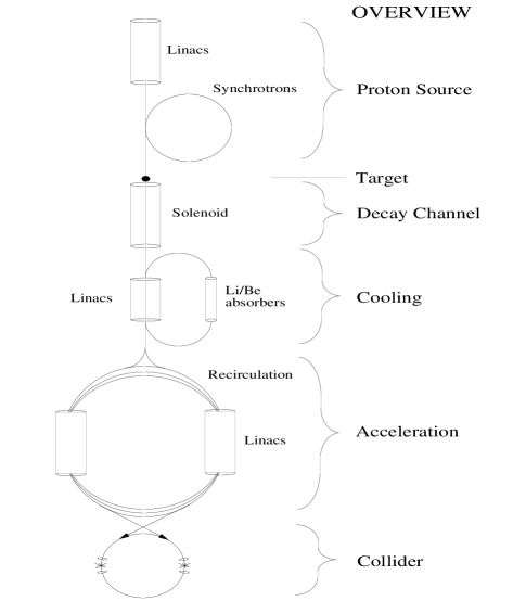
A high intensity proton source is bunch compressed and focussed on a heavy metal target. The pions generated are captured by a high field solenoid and transferred to a solenoidal decay channel within a low frequency linac. The linac serves to reduce, by phase rotation the momentum spread of the pions, and of the muons into which they decay. Subsequently, the muons are cooled by a sequence of ionization cooling stages. Each stage consists of energy loss, acceleration, and emittance exchange in energy absorbing wedges in the presence of dispersion. Once they are cooled the muons must be rapidly accelerated to avoid decay. This can be done in recirculating accelerators (à la CEBAF) or in fast pulsed synchrotrons. Collisions occur in a separate high field collider storage ring with very low beta insertion.
| 4 TeV | 0.5 TeV | Demo | ||
|---|---|---|---|---|
| Beam energy | TeV | 2 | 0.25 | 0.25 |
| Repetition rate | Hz | 15 | 15 | 2.5 |
| Muons per bunch | 2 | 4 | 4 | |
| Bunches of each sign | 2 | 1 | 1 | |
| Norm. rms emittance | mm mrad | 50 | 90 | 90 |
| at intersection | mm | 3 | 8 | 8 |
| Luminosity [units ] | 1 |
1.3 Physics Considerations
There are at least two physics advantages of a collider, when compared with a :
-
•
Because of the lack of beamstrahlung, a collider can be operated with an energy spread of as little as 0.01 %. It is thus possible to use the collider for precision measurements of masses and widths, that would be hard, if not impossible, with an collider.
-
•
The direct coupling of a lepton-lepton system to a Higgs boson has a cross section that is proportional to the square of the mass of the lepton. As a result, the cross section for direct Higgs production from the system is 40,000 times that from an system.
However, there are liabilities:
-
•
It is relatively hard to obtain both polarization and good luminosity in a collider, whereas good polarization can be obtained in an collider without any loss in luminosity.
-
•
because of the decays of the muons, there will be a considerable background of photons, muons and neutrons in the detector. This background may be acceptable for some experiments, but it is certainly not as clean as an in collider.
1.4 Conclusion
It is thus reasonable, from both technical and physics considerations, to consider colliders as complementary to colliders, just as colliders are complementary to hadron machines.
2 SYSTEM COMPONENTS
2.1 Proton Driver
The specifications of the proton drivers are given in Tb.2. In the examples, the -source driver is a high-intensity ( protons per pulse) 30 GeV proton synchrotron. The preferred cycling rate would be 15 Hz, but for the demonstration using the AGSroser , the repetition rate is limited to 2.5 Hz and to GeV. For the lower energy machines, 2 final bunches are employed (one to make ’s and the other to make ’s). For high energy collider, four are used (two bunches of each sign).
Earlier studies had suggested that the driver could be a 10 GeV machine with the same charge per bunch, but a repetition rate of Hz. This specification was almost identical to that studiedref77 at ANL for a spallation neutron source. Studies at FNALmills have further established that such a specification is not unreasonable. But in order to reduce the cost of the muon phase rotation section and for minimizing the final muon longitudinal phase space, it appears now that the final proton bunch length should be 1 ns (or even less). This appears difficult to achieve at 10 GeV, but possible at 30 GeV. If it is possible to obtain such short bunches with a 10 GeV source, or if future optimizations allow the use of the longer bunches, then the use of a lower energy source could be preferred.
In order to achieve the required 1 ns (rms) bunch length, an RF sequence must be designed to phase rotate the bunch prior to extraction. The total final momentum spread, based on the ANL parameters (95% phase space of per bunch), is ( rms), and the space charge tune shift just before extraction would be approx 0.5. It might be necessary to perform this bunch compression in a separate high field ring to avoid space charge problems.
| 4 TeV | .5 TeV | Demo | ||
| Proton energy | GeV | 30 | 30 | 24 |
| Repetition rate | Hz | 15 | 15 | 2.5 |
| Protons per bunch | 2.5 | 2.5 | 2.5 | |
| Bunches | 4 | 2 | 2 | |
| Long. phase space/bunch | eV s | 4.5 | 4.5 | 4.5 |
| Final rms bunch length | ns | 1 | 1 | 1 |
2.2 Target and Pion Capture
Predictions of the nuclear Monte-Carlo program ARCarc suggest that production is maximized by the use of heavy target materials, and that the production is peaked at a relatively low pion energy (MeV), substantially independent of the initial proton energy. Fig. 2 shows the forward production as a function of proton energy and target material; the distributions are similar.

Fig.3 shows the energy distribution for and for 24 GeV protons on Hg.

The target could be either Cu (approximately 24 cm long by 2 cm diameter), or Hg (approximately 14 cm long by 2 cm diameter). A Hg target is being studied for the European Spallation Source and would be cooled by circulating the liquid. The Cu target would require water cooling.
Pions are captured from the target by a high-field (T) water cooled Bitter solenoid that surrounds it. Such a magnet is estimatedweggel to require about 14 MW: a significant but not unreasonable power. The ’s are then matched, using a suitable tapered fieldref9 , into a periodic superconducting solenoidal decay channel (T and radius cm).
Monte Carlo studies indicate a yield of 0.6 muons, of each sign, per initial proton, captured in the decay channel. But these pions have an extremely broad energy spectrum so that only about half of them (0.3 ) can be used.
2.3 Capture and Use of Both Signs
Protons on the target produce pions of both signs, and a solenoid will capture both, but the required subsequent RF systems will have opposite effects on each. One solution is to break the proton bunch into two, target them on the same target one after the other, and adjust the RF phases such as to act correctly on one sign of the first bunch and on the other sign of the second. This is the solution assumed in the parameters of this paper.
A second solution is to separate the pions of each charge prior to the use of RF, and feed the beams of each charge into different channels. A third possibility would be to separate the charges, delay the particles of one charge, recombine the charges, and feed them into a single channel with appropriate phases of RF.
After the target, and prior to the use of any RF or cooling, the beams have very large emittances and energy spread. Conventional charge separation using a dipole is not practical. But if a solenoidal channel is bent, then the particles trapped within that channel will drift drift in a direction perpendicular to the bend. With our parameters this drift is dominated by a term (curvature drift) that is linear with the forward momentum of the particles, and has a direction that depends on the sign of the charges. It has been suggested snake that if sufficient bend is employed, the two charges could then be separated by a septum and captured into two separate channels. When these separate channels are bent back to the same forward direction, then the momentum dispersion is separately removed in each new channel.
Although this idea is very attractive, it has some problems:
-
•
If the initial beam has a radius r=m, and if the momentum range to be accepted is then the required height of the solenoid just prior to separation is 2(1+F)r=m. Use of a lesser height will result in particle loss. Typically, the reduction in yield for a curved solenoid compared to a straight solenoid is about (due to the loss of very low and very high momentum pions), but this must be weighed against the fact that both charge signs are captured for each proton on target.
-
•
The system of bend, separate, and return bend will require significant length and must occur prior to the start of phase rotation (see below). Unfortunately, it appears that the cost of the phase rotation RF appears to be strongly dependent on keeping this distance as short as possible. On the other hand it may be advisable to separate the remnant proton beam and other charged debris exiting the target before the RF cavities. A curved solenoid would accomplish this as well as charge-separate pions.
Clearly, compromises will be involved, and more study of this concept is required.
2.4 Phase Rotation Linac
The pions, and the muons into which they decay, have an energy spread from about 0 - 3 GeV, with an rms/mean of , and with a peak at about 100 MeV. It would be difficult to handle such a wide spread in any subsequent system. A linac is thus introduced along the decay channel, with frequencies and phases chosen to deaccelerate the fast particles and accelerate the slow ones; i.e. to phase rotate the muon bunch. Tb.3 gives an example of parameters of such a linac. It is seen that the lowest frequency is 30 MHz: a low but not impossible frequency for a conventional structure.
| Linac | Length | Frequency | Gradient |
| m | MHz | MeV/m | |
| 1 | 3 | 60 | 5 |
| 2 | 29 | 30 | 4 |
| 3 | 5 | 60 | 4 |
| 4 | 5 | 37 | 4 |
A design of a reentrant 30 MHz cavity is shown in Fig. 4. Its parameters are given in Tb. 4. It has a diameter of approximately 2 m: only about one third that of a conventional pill-box cavity. To keep its cost down, it would be made of Al. Multipactoring would probably be suppressed by stray fields from the 5 T focusing coils, but could also be controlled by an internal coating of titanium nitride.
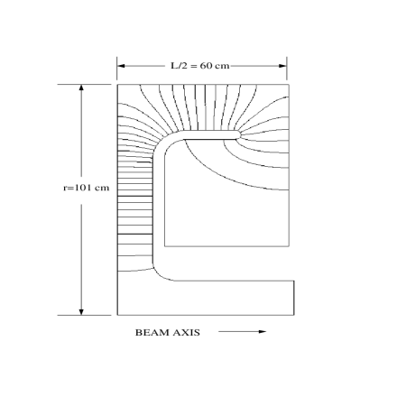
| Cavity Radius | cm | 101 |
| Cavity Length | cm | 120 |
| Beam Pipe Radius | cm | 15 |
| Accelerating Gap | cm | 24 |
| Q | 18200 | |
| Average Acceleration Gradient | MV/m | 3 |
| Peak RF Power | MW | 6.3 |
| Average Power (15 Hz) | KW | 18.2 |
| Stored Energy | J | 609 |
After this phase rotation, a bunch can be selected with mean energy 150 MeV, rms bunch length m, and rms momentum spread %. The number of muons per initial proton in this selected bunch is 0.3. Unfortunately, the linacs cannot phase rotate both signs in the same bunch: hence the need for two bunches. The phases are set to rotate the ’s of one bunch and the ’s of the other.
Prior to cooling, the bunch is accelerated to 300 MeV, at which energy the momentum spread is 10 %.
2.5 Ionization Cooling
2.5.1 Cooling Theory
For collider intensities, the phase-space volume must be reduced within the lifetime. Cooling by synchrotron radiation, conventional stochastic cooling and conventional electron cooling are all too slow. Optical stochastic coolingref11 , electron cooling in a plasma dischargeref12 and cooling in a crystal latticeref13 are being studied, but appear very difficult. Ionization coolingref14 of muons seems relatively straightforward.
In ionization cooling, the beam loses both transverse and longitudinal momentum as it passes through a material medium. Subsequently, the longitudinal momentum can be restored by coherent reacceleration, leaving a net loss of transverse momentum. Ionization cooling is not practical for protons and electrons because of nuclear interactions (p’s) and bremsstrahlung (e’s) effects in the material, but is practical for ’s because of their low nuclear cross section and relatively low bremsstrahlung.
The equation for transverse cooling (with energies in GeV) is:
| (1) |
where is the normalized emittance, is the betatron function at the absorber, is the energy loss, and is the material radiation length. The first term in this equation is the coherent cooling term, and the second term is the heating due to multiple scattering. This heating term is minimized if is small (strong-focusing) and is large (a low-Z absorber).
From Eq.1 we find a limit to transverse cooling, which occurs when heating due to multiple scattering balances cooling due to energy loss. The limits are for Li, and for Be.
The equation for energy spread (longitudinal emittance) is:
| (2) |
where the first term is the cooling (or heating) due to energy loss, and the second term is the heating due to straggling.
Cooling requires that But at energies below about 200 MeV, the energy loss function for muons, , is decreasing with energy and there is thus heating of the beam. Above 400 MeV the energy loss function increases gently, thus giving some cooling, though not sufficient for our application.
In the long-path-length Gaussian-distribution limit, the heating term (energy straggling) is given byref15
| (3) |
where is Avogadro’s number and is the density. Since the energy straggling increases as , and the cooling system size scales as , cooling at low energies is desired.
Energy spread can also be reduced by artificially increasing by placing a transverse variation in absorber density or thickness at a location where position is energy dependent, i.e. where there is dispersion. The use of such wedges can reduce energy spread, but it simultaneously increases transverse emittance in the direction of the dispersion. Six dimensional phase space is not reduced, but it does allow the exchange of emittance between the longitudinal and transverse directions.
2.5.2 Cooling System
We require a reduction of the normalized transverse emittance by almost three orders of magnitude (from to m-rad), and a reduction of the longitudinal emittance by more than one order of magnitude. This cooling is obtained in a series of cooling stages. In general, each stage consists of three components with matching sections between them:
-
1.
a lattice consisting of spaced axial solenoids with alternating field directions and lithium hydride absorbers placed at the centers of the spaces between them, where the ’s are minimum.
-
2.
a lattice consisting of more widely separated alternating solenoids, and bending magnets to generate dispersion. At the location of maximum dispersion, wedges of lithium hydride are introduced to interchange longitudinal and transverse emittance;
-
3.
a short linac to restore the energy lost in the absorbers.
At the end of this sequence of cooling stages, the transverse emittance can be reduced to about m, still a factor of above the emittance goals of Tb.1. The longitudinal emittance, however, can be cooled to a value nearly three orders of magnitude less than is required. The additional reduction of transverse emittance can then be obtained by a reverse exchange of transverse and longitudinal phase-spaces. Again this is done by the use of wedged absorbers in dispersive regions between solenoid elements.
Throughout this process appropriate momentum compaction and RF fields must be used to control the bunch, in the presence of space charge, wake field and resistive wall effects.
In a few of the later stages, current carrying lithium rods might replace item (1) above. In this case the rod serves simultaneously to maintain the low , and attenuate the beam momenta. Similar lithium rods, with surface fields of T , were developed at Novosibirsk and have been used as focusing elements at FNAL and CERN ref16 ). It is hoped20Tli that liquid lithium columns, can be used to raise the surface field to 20 T and improve the resultant cooling.
It would be desirable, though not necessarily practicable, to economize on linac sections by forming groups of stages into recirculating loops.
2.5.3 Example
A model example has been generated that uses no lithium rods and no recirculating loops. Individual components of the lattices used have been defined, but a complete lattice has not yet been specified and no Monte Carlo study of its performance has yet been performed. Spherical aberration due to solenoid end effects, wake fields, and second order RF effects have not yet been included.
The phase advance in each cell of the lattice is made as close to as possible in order to minimize the ’s at the location of the absorber, but it is kept somewhat less than this value so that the phase advance per cell should never exceed The following effects are included:
-
1.
the maximum space charge transverse defocusing
-
2.
a 3 fluctuation of momentum
-
3.
a 3 fluctuation in amplitude
In all but the final stages of cooling it is assumed that both charges will use the same channel. Bending magnets are introduced to generate dispersion, but the dispersion is kept equal to zero at the center of all solenoids. The maximum allowed beam angle with respect to the axis, due to dispersion, is 45 degrees.
In the early stages, the solenoids are relatively large and their fields are limited to T. In later stages the emittance has decreased, the apertures are smaller and the fields are increased to T. The maximum bending fields used are T, but most are at T.
The emittances, transverse and longitudinal, as a function of stage number, are shown in Fig.5, together with the beam energy. In the first 15 stages, relatively strong wedges are used to rapidly reduce the longitudinal emittance, while the transverse emittance is reduced relatively slowly. The object here is to reduce the bunch length, thus allowing the use of higher frequency and higher gradient RF in the reacceleration linacs. In the next 10 stages, the emittances are reduced close to their asymptotic limits. The charges are now separated for the last two stages. In these stages, the transverse and longitudinal emittances are again exchanged, but in the opposite direction: lowering the transverse and raising the longitudinal. During this exchange the energy is allowed to fall to 10 MeV in order to minimize the , and thus limit the emittance dilution.
The total length of the system is 880 m, and the total acceleration used is 2.7 GeV. The fraction of muons remaining at the end of the cooling system is calculated to be %.

2.6 Acceleration
Following cooling and initial bunch compression the beams must be accelerated to full energy (2 TeV, or 250 GeV). A sequence of linacs would work, but would be expensive. Conventional synchrotrons cannot be used because the muons would decay before reaching the required energy. The conservative solution is to use a sequence of recirculating accelerators (similar to that used at CEBAF). A more economical solution would be to use fast rise time pulsed magnets in synchrotrons, or synchrotrons with rapidly rotating permanent magnets interspersed with high field fixed magnets.
2.6.1 Recirculating Acceleration
Tb.5 gives an example of a possible sequence of recirculating accelerators. After an initial linac from 0.2 1 GeV, there are two conventional RF recirculating accelerators taking the muons up to 75 GeV, then two superconducting recirculators going up to 2000 GeV.
| Linac | #1 | #2 | #3 | #4 | ||
| initial energy | GeV | 0.20 | 1 | 8 | 75 | 250 |
| final energy | GeV | 1 | 8 | 75 | 250 | 2000 |
| nloop | 1 | 12 | 18 | 18 | 18 | |
| freq. | MHz | 100 | 100 | 400 | 1300 | 2000 |
| linac V | GV | 0.80 | 0.58 | 3.72 | 9.72 | 97.20 |
| grad | 5 | 5 | 10 | 15 | 20 | |
| dp/p initial | % | 12 | 2.70 | 1.50 | 1 | 1 |
| dp/p final | % | 2.70 | 1.50 | 1 | 1 | 0.20 |
| initial | mm | 341 | 333 | 82.52 | 14.52 | 4.79 |
| final | mm | 303 | 75.02 | 13.20 | 4.36 | 3.00 |
| % | 1.04 | 0.95 | 1.74 | 3.64 | 4.01 | |
| 2.59 | 2.35 | 2.17 | 2.09 | 2 | ||
| s | 87.17 | 87.17 | 10.90 | s.c. | s.c. | |
| beam t | s | 0.58 | 6.55 | 49.25 | 103 | 805 |
| decay survival | 0.94 | 0.91 | 0.92 | 0.97 | 0.95 | |
| linac len | km | 0.16 | 0.12 | 0.37 | 0.65 | 4.86 |
| arc len | km | 0.01 | 0.05 | 0.45 | 1.07 | 8.55 |
| tot circ | km | 0.17 | 0.16 | 0.82 | 1.72 | 13.41 |
| phase slip | deg | 0 | 38.37 | 7.69 | 0.50 | 0.51 |
Criteria that must be considered in picking the parameters of such accelerators are:
-
•
The wavelengths of rf should be chosen to limit the loading, , (it is restricted to below 4 % in this example) to avoid excessive longitudinal wakefields and the resultant emittance growth.
-
•
The wavelength should also be sufficiently large compared to the bunch length to avoid second order effects (in this example: 10 times).
-
•
For power efficiency, the cavity fill time should be long compared to the acceleration time. When conventional cavities cannot satisfy this condition, superconducting cavities are required.
-
•
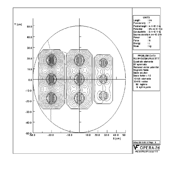
In order to minimize muon decay during acceleration (in this example 73% of the muons are accelerated without decay), the number of recirculations at each stage should be kept low, and the RF acceleration voltage correspondingly high. But for the minimum cost the number of recirculations appears to be of the order of 20 - a relatively high number. In order to avoid a large number of separate magnets, multiple aperture magnets can be designed (see Fig.6).
Note that the linacs see two bunches of opposite signs, passing through in opposite directions. In the final accelerator in the 2 TeV case, each bunch passes through the linac 18 times. The total loading is then With this loading, assuming 60% klystron efficiencies and reasonable cryogenic loads, one could probably achieve 35% wall to beam power efficiency, giving a wall power consumption for the RF in this ring of 108 MW.
A recent studyneufferacc tracked particles through a similar sequence of recirculating accelerators and found a dilution of longitudinal phase space of the order of 15%.
2.6.2 Pulsed Magnet Synchrotron Alternatives
An alternative to recirculating accelerators for stages #2 and #3 would be to use pulsed magnet synchrotrons. The cross section of a pulsed magnet for this purpose is shown in Fig. 7. If desired, the number of recirculations could be higher in this case, and the needed RF voltage correspondingly lower, but the loss of particles from decay would be somewhat more. The cost for a pulsed magnet system appears to be significantly less than that of a multi-hole recirculating magnet system, but its power consumption seems impractical at energies above 250 GeV.

2.6.3 Pulsed and Rotating Magnet Alternatives for the Final Accelerator
For the final acceleration to 2 TeV in the high energy machine, the power consumed by pulsed magnets would be excessive. A recirculating accelerator is still usable, but there are two other, possibly cheaper, alternatives being considered:
a) A sequence of two hybrid accelerators (0.25-1, and 1-2 TeV), each employing superconducting fixed magnets (e.g. T) alternating with pairs of counter-rotating permanent magnetsrotating . The power consumption would be negligible, but its practicality is not yet clear.
b) A similar sequence of two hybrid accelerators (0.25-1, and 1-2 TeV), each again employing alternate superconducting fixed magnets (e.g. T), but instead of pairs of rotating magnets, pulsed warm magnets (whose fields might swing from -1.5 T to +1.5 T) would be used. The power consumption would be considerable, but the initial cost might be significantly less than that for a recirculating accelerator, and it might be more practical than the rotating magnet scheme.
2.7 Storage Ring
After acceleration, the and bunches are injected into a separate storage ring. The highest possible average bending field is desirable, to maximize the number of revolutions before decay, and thus maximize the luminosity. Collisions would occur in one, or perhaps two, very low- interaction areas. Parameters of the rings are given in Tb.6.
| 4 TeV | .5 TeV | Demo. | ||
| Beam energy | TeV | 2 | .25 | .25 |
| Beam | 19,000 | 2,400 | 2,400 | |
| Repetition rate | Hz | 15 | 15 | 2.5 |
| Muons per bunch | 2 | 4 | 4 | |
| Bunches of each sign | 2 | 1 | 1 | |
| Normalized rms emittance | mm mrad | 50 | 90 | 90 |
| Bending Field | T | 9 | 9 | 8 |
| Circumference | Km | 7 | 1.2 | 1.5 |
| Average ring mag. field | T | 6 | 5 | 4 |
| Effective turns before decay | 900 | 800 | 750 | |
| at intersection | mm | 3 | 8 | 8 |
| rms beam size at I.P. | 2.8 | 16 | 16 | |
| Luminosity | 5 |
The bunch populations decay exponentially, yielding an integrated luminosity equal to its initial value multiplied by an effective number of turns where B is the mean bending field in T.
2.7.1 Bending Magnet Design
The magnet design is complicated by the fact that the ’s decay within the rings (), producing electrons whose mean energy is approximately 1/3 that of the muons. These electrons travel to the inside of the ring dipoles, radiating a substantial fraction of their energy as synchrotron radiation towards the outside of the ring. Fig.8 shows the attenuation of the heating produced as a function of the thickness of a warm tungsten liner.

If conventional superconductor is used, then the thicknesses required in the three cases would be as given in Tb.7. If high Tc superconductors could be used then these thicknesses could probably be halved.
| 2TeV | 0.5 TeV | Demo | ||
|---|---|---|---|---|
| Unshielded Power | MW | 17 | 4 | .5 |
| Liner thickness | cm | 4.5 | 3 | 2 |
| Power leakage | KW | 170 | 150 | 50 |
2.7.2 Lattice Design
Studiesstability of the resistive wall impedance instabilities indicate that the required muon bunches (eg for TeV: ) would be unstable in a conventional ring. In any case, the RF requirements to maintain such bunches would be excessive. It is thus proposed to use an isochronous lattice of the type discussed by S.Y. Lee et alref17 . The elements of such a lattice have been designedDjan , and are being incorporated into a full ring.
It had been feared that amplitude dependent anisochronicity generated in the insertion would cause bunch growth in an otherwise purely isochronous design. It has, however, been pointed out oide that if chromaticity is corrected in the ring, then amplitude dependent anisochronicity is automatically removed.
2.7.3 Low Insertion
In order to obtain the desired luminosity we require a very low beta at the intersection point: for 4 TeV, for .5 TeV. A possible final focusing quadruplet design is shown in Fig.9. The parameters of the quadrupoles for this quadruplet are given in Tb.8. With these elements, the maximum beta’s in both x and y are of the order of 400 km in the 4 TeV case, and 14 km in the 0.5 TeV machine. The chromaticities are approximately 6000 for the 4 TeV case, and 600 for the .5 TeV machine. Such chromaticities are too large to correct within the rest of a conventional ring and therefore require local correction ofref18 .
| MeV | MeV | ||||
|---|---|---|---|---|---|
| field (T) | L(m) | R(cm) | L(m) | R(cm) | |
| drift | 6.5 | 1.99 | |||
| focus | 6 | 6.43 | 6 | 1.969 | 5.625 |
| drift | 4.0 | 1.2247 | |||
| defocus | 6.4 | 13.144 | 12 | 4.025 | 11.25 |
| drift | 4.0 | 1.2247 | |||
| focus | 6.4 | 11.458 | 12 | 3.508 | 11.25 |
| drift | 4.0 | 1.2247 | |||
| defocus | 6.348 | 4.575 | 10 | 1.400 | 9.375 |
| drift | 80 | 24.48 | |||

A preliminary model designff of local chromatic correction (for the 4 TeV case) has been presented. Fig.10 shows the horizontal dispersion and beta functions for this design.

Fig.11 shows the tune shift as a function of momentum. It is seen that this design has a momentum acceptance of . The second order amplitude dependent tune shifts appear acceptable in this design, but the bending fields are unrealistic. It is expected that these limitations will soon be overcome, and that more sophisticated designsref19 should do even better. It is hoped to achieve a momentum acceptance of for use with a clipped rms momentum spread of 0.2 %.

3 COLLIDER PERFORMANCE
3.1 Luminosity, Energy and Momentum Spread
The luminosity is given by:
| (4) |
where and the enhancement factor is
The luminosities given in Tb.1 are those for the design energy and energy spread. At lower energies, or energy spread, the luminosities will be lower.
For a fixed collider lattice, operating at energies lower than the design value, the luminosity will fall as One power comes from the in the above equation; a second comes from , the effective number of turns, that is proportional to ; the third term comes from which must be increased proportional to in order to keep the beam size constant within the focusing magnets. The bunch length must also be increased so that the required longitudinal phase space is not decreased.
In view of this rapid drop in luminosity with energy, it would be desirable to have separate collider rings at relatively close energy spacings: e.g. not more than factors of two apart.
If it is required to lower the energy spread at a fixed energy, then, given the same longitudinal phase space, the bunch length must be increased. If the final focus is retuned to simultaneously increase to maintain the value of then the luminosity will be exactly proportional to But if, instead, the is kept constant, and the parameter A allowed to increase, then the luminosity falls initially at a somewhat lower rate. The luminosity, for small is then approximately given by:
| (5) |
There may, however, be tune shift emittance growth problems in this case.
3.2 Detector Background
There will be backgrounds from the decay of muons in the ring, from muon halo around the beam, and there will be backgrounds from the interactions themselves.
3.2.1 Muon Decay Background
A first Monte Carlo studyref20 of the muon decay background was done with the MARS95 coderef21 , based on a preliminary insertion lattice. A tungsten shielding nose was introduced, extending to within 15 cm of the intersection point. It was found that:
-
•
a large part of the electromagnetic background came from synchrotron radiation, due to the bending magnets in the chromatic correction section.
-
•
As many as 500 hits per cm2 were expected in a vertex detector, falling to of the order of 2 hits per cm2 in an outer tracker.
-
•
There was considerable, very low energy neutron background: of the order of 30,000 neutrons per giving, with an efficiency of , about 100 hits per cm2.
It was hoped that by improving the shielding these backgrounds could be substantially reduced.
A more recent studyiuliu of the electromagnetic component of the background has been done using the GEANT codesgeant . This study differed from the first in several ways:
-
•
the shower electrons and photons were followed down to a lower energy (keV for electrons and keV for photons).
-
•
The nose angle, i.e. the angle not seen by the detector, was increased from 9 to 20 degrees.
-
•
The nose design was modified (see Fig.12) so that: 1) The incoming electrons are collimated to (where is the rms divergence of the beam) by a cone leading down towards the vertex. 2) The detector could not see any surface directly illuminated by these initial electrons, whether seen in the forward or backward (albedo) directions. 3) The detector could not see any surface that is illuminated by secondary electrons if the secondary scattering angle is forward. 4) The minimum distance through the collimator from the detector to any primarily illuminated surface was more than 100 mm, and from any secondarily illuminated surface, 30 mm.

Figure 12: Schematic of the detector nose. -
•
It was assumed that a collimator placed at a focus 130 m from the intersection point would be able to effectively shield all synchrotron photons from the bending magnets beyond that point (the rms beam size at this focus is only 10 ).
This study indicated that the dominant background was not from synchrotron photons, but from decay electrons. The average momentum of these photons was only 1 MeV. and the sensitivity of detectors to such low energy photons is only about 0.3% for silicon detectors and as low as 0.1% for a suitably designed gas detector. Tb.9 gives the total numbers of photons, the total number of hits, possible pixel sizes, and the hits per pixel, for a) a vertex detector placed at a 5 cm radius, and b) a gas detector placed at a 1 m radius. In all cases the numbers are given per bunch crossing.
| Detector | vertex | tracker |
|---|---|---|
| Radius | 5 cm | 1 m |
| Number of photons | ||
| Number of hits | 150,000 | 15,000 |
| Detector Area | 863 cm2 | 34 m2 |
| Pixel size | 20 x 20 m | 1 mm x 1 cm |
| Sensitivity | 0.3 % | 0.1 % |
| Occupancy | .07 % | 0.4 % |
This study found a relatively modest flux of muons from pair production in electromagnetic showers: about 50 such tracks pass through the detector per bunch crossing.
The general conclusion of this study is not inconsistent with that from the MARS study: the background, though serious, is not apparently impossible. Further reductions are expected as the shielding is optimized, and it may be possible to design detectors that are less sensitive to the very low energy neutrons and photons present.
3.2.2 Muon Halo Background
There would be a very serious background from the presence of even a very small halo of near full energy muons in the circulating beam. The beam will need careful preparation before injection into the collider, and a collimation system will be designed to be located in the ring, possibly on the opposite side from the detector.
3.2.3 Electron Pair Background
In machines there is a significant problem from beamstrahlung photons (synchrotron radiation of beam particles in the coherent field of the oncoming bunch), and an additional problem from pair production from these photons.
With muons, there is negligible beamstrahlung, and thus negligible pair production from these real photons. Pisin Chenbeamstrahlung has further shown that beamstrahlung of electrons from the nearby decay of muons does not pose a problem.
There is, however, significant incoherent (i.e. ) pair production in the 4 TeV Collider case. The cross section is estimated to be mbpairsection , which would give rise to a background of electron pairs per bunch crossing. Most of these, approximately , will be trapped inside the tungsten nose cone, but those with energy between 30 and MeV will enter the detector region.
There remains some question about the coherent pair production generated by the virtual photons interacting with the coherent electromagnetic fields of the entire oncoming bunch. A simple Weizsäcker-Williams calculationpisin yields a background so disastrous that it would consume the entire beam at a rate comparable with its decay. However, I. Ginzburgginzburg and others have argued that the integration must be cut off due to the finite size of the final electrons. If this is true, then the background becomes negligible.
If the coherent pair production problem is confirmed, then there are two possible solutions: 1) one could design a two ring, four beam machine (a and a bunch coming from each side of the collision region, at the same time). In this case the coherent electromagnetic fields at the intersection are canceled and the pair production becomes negligible. 2) Plasma could be introduced at the intersection point to cancel the beam electromagnetic fieldsplasma .
4 CONCLUSION
-
•
The scenario for a 2 + 2 TeV, high luminosity collider is by no means complete. There are many problems still to be examined. Much work remains to be done, but no obvious show stopper has yet been found.
-
•
Many technical components require development: a large high field solenoid for capture, low frequency RF linacs, long lithium lenses, multi-beam pulsed and/or rotating magnets for acceleration, warm bore shielding inside high field dipoles for the collider, muon collimators and background shields, but:
-
•
None of the required components may be described as exotic, and their specifications are not far beyond what has been demonstrated.
-
•
If the components can be developed and if the problems can be overcome, then a muon-muon collider may be a viable tool for the study of high energy phenomena, complementary to and hadron colliders.
5 ACKNOWLEDGMENTS
We acknowledge extremely important contributions from our colleagues, especially W. Barletta, A. Chao, D. Cline, D. Douglas, D. Helms, J. Irwin, K. Oide, H. Padamsee, Z. Parsa, C. Pellegrini, A. Ruggiero, W. Willis and Y. Zhao.
This research was supported by the U.S. Department of Energy under Contract No. DE-ACO2-76-CH00016 and DE-AC03-76SF00515.
References
- (1) E. A. Perevedentsev and A. N. Skrinsky, Proc. 12th Int. Conf. on High Energy Accelerators, F. T. Cole and R. Donaldson, Eds., (1983) 485; A. N. Skrinsky and V.V. Parkhomchuk, Sov. J. of Nucl. Physics 12, (1981) 3; Early Concepts for Colliders and High Energy Storage Rings, Physics Potential & Development of Colliders. 2nd Workshop, Sausalito, CA, Ed. D. Cline, AIP Press, Woodbury, New York, (1995).
- (2) D. Neuffer, IEEE Trans. NS-28, (1981) 2034.
- (3) Proceedings of the Mini-Workshop on Colliders: Particle Physics and Design, Napa CA, Nucl Inst. and Meth., A350 (1994) ; Proceedings of the Muon Collider Workshop, February 22, 1993, Los Alamos National Laboratory Report LA- UR-93-866 (1993) and Physics Potential & Development of Colliders 2nd Workshop, Sausalito, CA, Ed. D. Cline, AIP Press, Woodbury, New York, (1995).
- (4) Transparencies at the 2 + 2 TeV Collider Collaboration Meeting, Feb 6-8, 1995, BNL, compiled by Juan C. Gallardo; transparencies at the 2 + 2 TeV Collider Collaboration Meeting, July 11-13, 1995, FERMILAB, compiled by Robert Noble.
- (5) D. V. Neuffer, R. B. Palmer, Proc. European Particle Acc. Conf., London (1994); M. Tigner, in Advanced Accelerator Concepts, Port Jefferson, NY 1992, AIP Conf. Proc. 279, 1 (1993).
- (6) Overall Parameters and Construction Techniques Working Group report, Proceedings of the Fifth International Workshop on Next-Generation Linear Colliders, Oct 13-21, 1993, Slac-436, pp.428.
- (7) R. B. Palmer et al., Monte Carlo Simulations of Muon Production, Physics Potential & Development of Colliders 2nd Workshop, Sausalito, CA, Ed. D. Cline, AIP Press, Woodbury, New York, pp. 108 (1995).
- (8) T. Roser, AGS Performance and Upgrades: A Possible Proton Driver for a Muon Collider, this proceedings.
- (9) Y. Cho, et al., A 10-GeV, 5-MeV Proton Source for a Pulsed Spallation Source, Proc. of the 13th Meeting of the Int’l Collaboration on Advanced Neutron Sources, PSI Villigen, Oct. 11-14 (1995); Y. Cho, et al., A 10-GeV, 5-MeV Proton Source for a Muon-Muon Collider, this proceedings.
- (10) F. Mills, et al., presentation at this Wokshop, unpublished; see also second reference in ref5 .
- (11) D. Kahana, et al., Proceedings of Heavy Ion Physics at the AGS-HIPAGS ’93, Ed. G. S. Stephans, S. G. Steadman and W. E. Kehoe (1993); D. Kahana and Y. Torun, Analysis of Pion Production Data from E-802 at 14.6 GeV/c using ARC, BNL Report # 61983 (1995).
- (12) R. Weggel, private communication; Physics Today, pp. 21-22, Dec. (1994).
- (13) R. Chehab, J. Math. Phys. 5, (1978) 19
- (14) F. Chen, Introduction to Plasma Physics, Plenum, New York, pp. 23-26 (9174); T. Tajima, Computational Plasma Physics: With Applications to Fusion and Astrophysics, Addison-Wesley Publishing Co., New York, pp. 281-282 (1989).
- (15) N. Mokhov, R. Noble and A. Van Ginneken, Target and Collection Optimization for Muon Colliders, this proceedings.
- (16) A. A. Mikhailichenko and M. S. Zolotorev, Phys. Rev. Lett. 71, (1993) 4146; M. S. Zolotorev and A. A. Zholents, SLAC-PUB-6476 (1994)
- (17) Ady Hershcovitch, Brookhaven National Report AGS/AD/Tech. Note No. 413 (1995)
- (18) Z. Huang, P. Chen, R. Ruth, SLAC-PUB-6745, Proc. Workshop on Advanced Accelerator Concepts, Lake Geneva, WI , June (1994); P. Sandler, A. Bogacz and D. Cline, Muon Cooling and Acceleration Experiment Using Muon Sources at Triumf, Physics Potential & Development of Colliders 2nd Workshop, Sausalito, CA, Ed. D. Cline, AIP Press, Woodbury, New York, pp. 146 (1995).
- (19) Initial speculations on ionization cooling have been variously attributed to G. O’Neill and/or G. Budker see D. Neuffer, Particle Accelerators, 14, (1983) 75; D. Neuffer, Proc. 12th Int. Conf. on High Energy Accelerators, F. T. Cole and R. Donaldson, Eds., 481 (1983); D. Neuffer, in Advanced Accelerator Concepts, AIP Conf. Proc. 156, 201 (1987); see also ref2 .
- (20) U. Fano, Ann. Rev. Nucl. Sci. 13, 1 (1963).
- (21) G. Silvestrov, Proceedings of the Muon Collider Workshop, February 22, 1993, Los Alamos National Laboratory Report LA-UR-93-866 (1993); B. Bayanov, J. Petrov, G. Silvestrov, J. MacLachlan, and G. Nicholls, Nucl. Inst. and Meth. 190, (1981) 9; Colin D. Johnson, Hyperfine Interactions, 44 (1988) 21; M. D. Church and J. P. Marriner, Annu. Rev. Nucl. Sci. 43 (1993) 253.
- (22) G. Silvestrov, presentation at this Workshop, unpublished.
- (23) D. Neuffer, presentation at this Workshop, unpublished.
- (24) D. Summers, presentation at this Workshop, unpublished.
- (25) M. Syphers, private communication; K.-Y. Ng, Beam Stability Issues in a Quasi-Isochronous Muon Collider, this proceedings.
- (26) S.Y. Lee, K.-Y. Ng, D. Trbojevic, FNAL Report FN595 (1992); Phys. Rev. E48, (1993) 3040.
- (27) K. Oide, private communication.
- (28) D. Trbojevic, et al., Design of the Muon Collider Isochronous Storage Ring Lattice, Micro-Bunches Workshop, BNL Oct. (1995), to be published.
- (29) K. L. Brown , J Spencer, SLAC-PUB-2678 (1981) presented at the Particle Accelerator Conf., Washington, (1981) and K.L. Brown, SLAC-PUB-4811 (1988), Proc. Capri Workshop, June 1988 and J.J. Murray, K. L. Brown, T.H. Fieguth, Particle Accelerator Conf., Washington, 1987.
- (30) Bruce Dunham, Olivier Napoly, FFADA, Final Focus. Automatic Design and Analysis, CERN Report CLIC Note 222, (1994); Olivier Napoly, it CLIC Final Focus System: Upgraded Version with Increased Bandwidth ans Error Analysis, CERN Report CLIC Note 227, (1994).
- (31) Juan C. Gallardo, Robert B. Palmer, Final Focus System for a Muon Collider: A Test Model, BNL #, CAP 138-MUON-96R (1996)
- (32) K. Oide, SLAC-PUB-4953 (1989); J. Irwin, SLAC-PUB-6197 and LBL-33276, Particle Accelerator Conf.,Washington, DC, May (1993); R. Brinkmann, Optimization of a Final Focus System for Large Momentum Bandwidth, DESY-M-90/14 (1990).
- (33) G. W. Foster, and N. V. Mokhov, Backgrounds and Detector Performance at 2 + 2 TeV Collider, Physics Potential & Development of Colliders 2nd Workshop, Sausalito, CA, Ed. D. Cline, AIP Press, Woodbury, New York, pp. 178 (1995).
- (34) N. V. Mokhov, The MARS10 Code System, Fermilab FN-509 (1989); The MARS95 Code System (User’s Guide), to be published as Fermilab Report.
- (35) I. Stumer, private communication
- (36) Geant Manual, Cern Program Library V. 3.21, Geneva, Switzerland, 1993.
- (37) P. Chen presentation at this Workshop, unpublished.
- (38) L. D. Landau and E. M. Lifshitz, Phys. Zs. Sowjetunion 6, 244 (1934); V. M. Budnev, I. F. Ginzburg, G. V. Medelin and V. G. Serbo, Phys Rep., 15C, 181 (1975
- (39) P. Chen presentation at this Workshop, unpublished.
- (40) I. Ginzburg, private communication.
- (41) G. V. Stupakov, P. Chen, Plasma Suppression of Beam-Beam Interaction in Circular Colliders, SLAC Report: SLAC-PUB-95-7084 (1995)