Harmonic Cancellation in Multi-Electrolyzer P2H Plants via Phasor-Modulated Production Scheduling
Abstract
Thyristor rectifiers (TRs) are cost-effective power supplies for hydrogen electrolyzers (ELZs) but introduce harmonic distortion that may violate grid codes. This letter proposes a self-governing harmonic mitigation strategy through coordinated operation of multiple ELZs in large power-to-hydrogen (P2H) plants. First, the harmonic model of TR-powered ELZs is derived, revealing a natural harmonic cancellation mechanism among them. Based on this, a system-level operation scheme based on phasor modulation is developed and integrated into plant scheduling. Case studies demonstrate that the proposed method reduces harmonic currents by 21.2%–39.7% and ensures grid-code compliance, with only a 0.25% loss in hydrogen output, while increasing total revenue by over 21% compared to production-oriented strategies.
I Introduction
Renewable power-to-hydrogen (ReP2H) offers promising pathways for green transition in the power and chemical sectors [1]. As ReP2H projects expand in number and capacity, they employ multiple electrolyzers (ELZs), many powered by thyristor rectifiers (TRs) [1] for their cost-effectiveness. However, the phase-controlled nature of TRs introduces harmonic distortion that may violate grid codes such as IEEE 519 [2] and GB/T 14549–93 [3]; for example, a 12-pulse TR typically yields more than 6% total harmonic distortion (THD) [4].
Existing harmonic mitigation approaches include multipulse rectification and active/passive power filters (APFs/PPFs), each with inherent tradeoffs. PPFs are inexpensive but unsuitable for fast-varying operating conditions [5]. APFs and multipulse TRs are costly due to complex designs involving bidirectional PWM converters and phase-shifting transformers [6]. The industry requires low-cost harmonic mitigation solutions.
Several studies have addressed this challenge. Meng et al. [6] proposed a hybrid rectifier, though its complexity hinders large-scale deployment. Yang et al. [7] developed a phase-shifted current control scheme for motor drive systems, but it overlooks the on-off switching and load variations of ELZs.
In contrast to device-level approaches, this letter focuses on system-level solutions. It quantifies the coupling between harmonics and hydrogen production, identifies a tradeoff between harmonics and P2H efficiency, and proposes a harmonic mitigation method. The main contributions are:
1) Identification of a self-governing harmonic cancellation mechanism in multi-ELZ systems, where adjusting electrolytic currents modulates harmonic phasors and reduces overall harmonic injections.
2) Formulation of a feasible region-based harmonic mitigation paradigm and its integration into plant scheduling.
II Harmonic Model and Mitigation Strategy
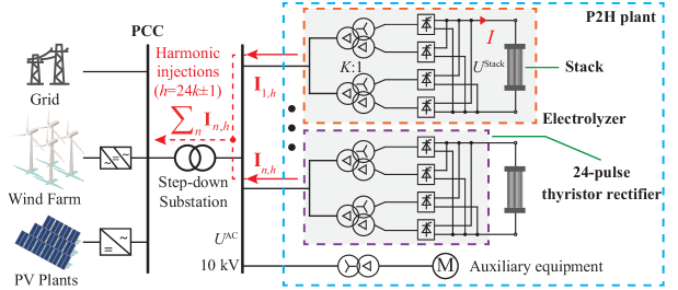
As shown in Fig. 1, we assume the ELZs are powered by 24-pulse rectifiers [1, 8], which generate ()th harmonic currents. The harmonic phasors from all ELZs are superposed at the point of common coupling (PCC) before being injected into the grid, which must satisfy grid-code harmonic limits.
II-A Harmonic Model of TR-Powered ELZs
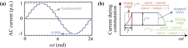
Let the ELZs be rated at 5 MW, consisting of cells and operating within 2–7 kA. The AC-side current exhibits a 24-step rectangular waveform shown in Fig. 2(a). Due to line inductance, commutation is not instantaneous, as illustrated in Fig. 2(b) [9]. Considering the firing angle and commutation overlap , a Fourier analysis yields the th harmonic component , where and denote the th harmonic and fundamental components, respectively. The analytical expression of is not presented due to its complexity.
To associate with ELZ operation, the relationships , and are established. Eq. (1) relates the DC-side stack voltage , commutation voltage drop , and electrolytic current , where is calculated by (2), and is determined via power conservation (3) [8].
| (1) | |||
| (2) | |||
| (3) |
where is the AC-side bus voltage determined by the grid [8]; is the transformer turn ratio; and is the commutation reactance. Solving (1)–(3) simultaneously provides , , and , which are substituted into to obtain .
Fig. 3 shows , , and as functions of the stack current . The phasors of the 23rd and 47th harmonics (including amplitude and phase) within the stack operation range [] are illustrated in Fig. 4. Higher-order harmonics are comparatively small and well below the grid-code thresholds [3], and thus not concerned here.

II-B Harmonic Cancellation Mechanism of Multiple ELZs
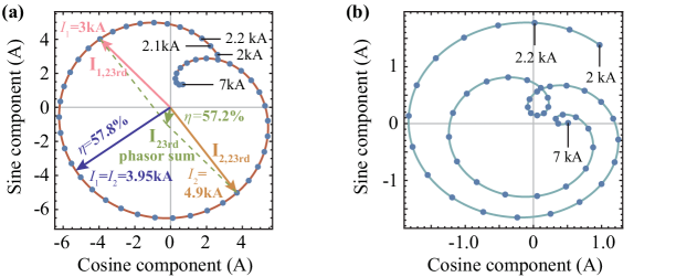
Fig. 4(a) shows that varying the electrolytic current modulates both the phase and magnitude of harmonic currents, enabling cancellation among multiple ELZs. For instance, when two ELZs operate at kA and kA, their 23rd harmonic currents exhibit nearly equal magnitudes and opposite phases, resulting in a near-zero phasor sum.
However, this allocation is suboptimal for hydrogen production compared with the evenly distributed current of 3.95 kA (P2H efficiency : 57.2% 57.8%; see the equimarginal principle in Appendix A of our prior work [1]). Thus, a tradeoff arises between harmonic mitigation and energy efficiency, motivating the following system-level operational paradigm.
II-C Operational Principle for Harmonic Mitigation
This subsection formulates the harmonic feasible region of an -ELZ P2H plant under GB/T 14549–93 [3], which requires the th harmonic current at the PCC to remain within
| (4) |
where , and are the PCC short-circuit capacity, base short-circuit capacity, and corresponding harmonic limit.
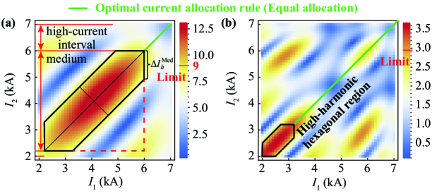
To satisfy these limits, the electrolytic loads of ELZs are coordinated to modulate their harmonic phasors. For clarity, two ELZs are first grouped to quantify harmonic limits as (with typically even). Numerical analysis of the 23rd and 47th harmonics shows that the infeasible region is approximately a symmetric hexagon, as shown in Fig. 5(a). Accordingly, the feasible region of the two-ELZ group can be expressed as
| (5) |
where indicates whether the th ELZ is active; are binary variables indicating the ELZ current being in low-, medium-, and high-current intervals ; denotes whether both ELZs operate in the medium interval; is the minimum electrolytic current difference ensuring harmonic compliance; is a large constant.
Remark 1.
For multiple ELZ groups, the harmonic limit generalizes to , where idle groups enlarge the feasible region of active ones. When , the th harmonic remains compliant. Hence, the binary variable identifies whether harmonic mitigation is required.
Although GB/T 14549 does not specify limits for the 47th and 49th harmonics, suppressing them remains beneficial. Restricting ELZs from operating in high-harmonic regions, as shown in Fig. 5(b), helps achieve this, and the same principle applies to current-distortion ratios defined in IEEE 519 [2].
II-D Integration into Plant Scheduling
The proposed harmonic constraints (5) can be easily incorporated into plant scheduling to jointly manage P2H efficiency and grid-code compliance. A simplified scheduling model (6)–(14) is formulated here for clarity; in practice, these rules (5) can be embedded in the comprehensive scheduling framework of our prior work [1], which also accounts for temperature dynamics, impurity limits of ELZs, and network power flow.
| (6) | ||||
| s.t. | (7) | |||
| (8) | ||||
| (9) | ||||
| (10) | ||||
| (11) | ||||
| (12) | ||||
| (13) | ||||
| (14) |
where the objective (6) maximizes total revenue by balancing hydrogen output and operational costs; (7)–(10) describe power balance and hydrogen production; (11)–(13) represent the on-standby-idle transition logic of each ELZ; and denote the scheduling horizon and step length; , , and are the hydrogen, electricity, and startup cost; and are renewable and grid power; , , and denote total, stack, and auxiliary power of each ELZ; is the hydrogen output; and are the Faraday efficiency and constant; and , , , and indicate the operational states and startup action.
III Case Studies
We compare the proposed method (PM) with two benchmarks: CM1 from [10], which optimizes hydrogen production without harmonic constraints; and CM2, which follows CM1’s on-off schedule but evenly distributes the load among ELZs, satisfying the harmonic constraint (5) by adjusting total load rather than using phasor modulation via load offsets. A 2-ELZ system from [8] and a large-scale 20-ELZ system from [1] are examined. The main operational parameters are listed in Table I.
| Parameter | Value | Parameter | Value | Parameter | Value |
|---|---|---|---|---|---|
| 26 CNY/kg [1] | 0.6 CNY/kWh | 1000 CNY [1] | |||
| 0.5 MW | , | 2 kA, 7 kA | , | 24, 1 h |
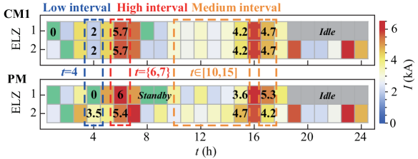
1) 2-ELZ Illustrative Case: In the 2-ELZ system, the rated voltage is 10 kV and the short-circuit capacity is MVA. Figs. 7 and 7 compare the ELZ state transitions, load allocation, and harmonic currents under CM1, CM2, and PM.
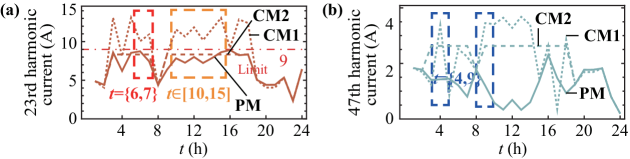
During high-current intervals, h, PM mitigates minor harmonic violations by slightly uneven load allocation among ELZs. In medium-load periods, h, CM1 exceeds the 23rd and 25th harmonic limits, whereas PM introduces small inter-ELZ current offsets to modulate phase differences, avoiding harmonic hotspots; see Fig. 5(a). Simultaneously, the 47th and 49th harmonics are also suppressed. At low loads, or h, rule (5) prevents both ELZs from operating at low current; thus, PM temporarily switches one unit to standby, effectively reducing harmonic injections.
Table II summarizes the performance metrics. CM1 yields the highest revenue but violates grid codes. PM reduces average harmonic currents by 19.4%–42.8% relative to CM1, with only a 0.8% revenue loss and 0.02% hydrogen output loss. Compared with CM2, PM achieves 28% higher revenue under similar harmonic levels, highlighting the effect of phasor modulation.
| Method | CM1 | CM2 | PM | ||
|---|---|---|---|---|---|
|
47.63 | 36.90 | 47.25 | ||
|
1867.2 | 2734.27 | 1866.8 | ||
|
1.53 | 56.99 | 2.14 | ||
|
✗ | ✓ | ✓ | ||
|
8.7/6.7/2.1/1.9 | 7.0/5.1/2.2/2.0 | 6.7/5.4/1.2/1.1 |
2) 20-ELZ Industrial Case: In the 20-ELZ system, the rated voltage is 220 kV and MVA. Table III compares CM1, CM2, and PM results. Relative to CM1, PM achieves 21.2%–39.7% reductions in harmonic currents with only 0.25% revenue and hydrogen output losses, while outperforming CM2 by over 21% in revenue under comparable harmonic levels. With higher system flexibility, large-scale plants benefit more significantly from coordinated harmonic management, validating the scalability and practical value of the proposed approach.
| Method | CM1 | CM2 | PM | ||
|---|---|---|---|---|---|
|
479.2 | 394.1 | 478.0 | ||
|
18463 | 25200 | 18417 | ||
|
1.37 | 435.23 | 1.35 | ||
|
✗ | ✓ | ✓ | ||
|
3.3/2.8/0.7/0.7 | 2.6/1.8/0.8/0.7 | 2.6/2.1/0.5/0.4 |
IV Conclusions
This letter addresses the harmonic compliance problem in P2H plants by establishing a harmonic model that quantifies the coupling between electrolytic currents and harmonic distortion. Building on this model, a system-level phasor modulation strategy is developed to coordinate multiple ELZs for self-governing harmonic cancellation. Rules are then formulated to integrate this mechanism into plant operation.
Case studies show that the dominant 23rd/25th harmonics arise in the medium-load range and the 47th/49th harmonics in the low-load range. The proposed method effectively suppresses these harmonics, ensuring grid-code compliance with only 0.25% reductions in hydrogen output and revenue.
Future research will investigate online harmonic feature extraction and optimal allocation of PPF/APFs and other resources to enable more grid-friendly large-scale P2H deployment.
References
- [1] Y. Zeng, et al., “Scheduling multiple industrial electrolyzers in renewable P2H systems: A coordinated active-reactive power management method,” IEEE Trans. Sustain. Energy, vol. 16, no. 1, pp. 201–215, Jan. 2025.
- [2] “IEEE recommended practice and requirements for harmonic control in electric power systems,” IEEE Std 519-2014 (Revision of IEEE Std 519-1992), pp. 1–29, 2014.
- [3] “Quality of electric energy supply–Harmonics in public supply network,” Standard GB/T 14549-93, National Standard of the People’s Republic of China, 1993, in Chinese.
- [4] Y. Gao, X. Wang, and X. Meng, “Advanced rectifier technologies for electrolysis-based hydrogen production: A comparative study and real-world applications,” Energies, vol. 18, no. 1, p. 48, 2024.
- [5] J. Das, “Passive filters-potentialities and limitations,” IEEE Trans. Ind. Appl., vol. 40, no. 1, pp. 232–241, Jan. 2004.
- [6] X. Meng, M. Chen, M. He, X. Wang, and J. Liu, “A novel high power hybrid rectifier with low cost and high grid current quality for improved efficiency of electrolytic hydrogen production,” IEEE Trans. Power Electron., vol. 37, no. 4, pp. 3763–3768, Apr. 2022.
- [7] Y. Yang, et al., “Enhanced phase-shifted current control for harmonic cancellation in three-phase multiple adjustable speed drive systems,” IEEE Trans. Power Deliv., vol. 32, no. 2, pp. 996–1004, Apr. 2017.
- [8] J. Li, B. Yang, J. Lin, F. Liu, Y. Qiu, Y. Xu, R. Qi, and Y. Song, “Two-layer energy management strategy for grid-integrated multi-stack power-to-hydrogen station,” Appl. Energy, vol. 367, p. 123413, Aug. 2024.
- [9] N. Mohan, T. M. Undeland, and W. P. Robbins, Power Electronics: Converters, Applications, and Design. John Wiley & Sons, 2003.
- [10] Y. Qiu, et al., “Extended load flexibility of utility-scale P2H plants: Optimal production scheduling considering dynamic thermal and HTO impurity effects,” Renew. Energy, vol. 217, p. 119198, Nov. 2023.