On the Robustness of RSMA to Adversarial BD-RIS-Induced Interference
Abstract
This article investigates the robustness of RSMA (RSMA) in multi-user MIMO (MIMO) systems to interference attacks against channel acquisition induced by BD-RIS. Two primary attack strategies, random and aligned interference, are proposed for fully connected and group-connected BD-RIS architectures. Valid random reflection coefficients are generated exploiting the Takagi factorization, while potent aligned interference attacks are achieved through optimization strategies based on a QCQP (QCQP) reformulation followed by projections onto the unitary manifold. Our numerical findings reveal that, when perfect CSI (CSI) is available, RSMA behaves similarly to SDMA (SDMA) and thus is highly susceptible to the attack, with BD-RIS inducing severe performance loss and significantly outperforming diagonal RIS. However, under imperfect CSI, RSMA consistently demonstrates significantly greater robustness than SDMA, particularly as the system’s transmit power increases.
Index Terms:
Reconfigurable intelligent surface, rate-splitting multiple access, physical-layer security, multi-user MIMO.I Introduction
6G introduces a range of new technologies that will positively contribute to improved service and feature offerings at the expense of greatly expanding the threat surface. \AcRIS is one example of a benign technology that is anticipated to contribute to improved coverage, spectral efficiency, and sensing services, but one that has also attracted significant interest in the adversarial context [1, 2, 3, 4, 5, 6, 7, 8]. Being a passive relay, RIS (RIS) can be used as a passive jammer that can adjust its reflective properties to execute an adversarial action, e.g., canceling the legitimate signal [1], aiding the active jammer [2], or poisoning the channel estimation process [3]. The latter attack is of particular severity, since channel acquisition is a critical component of advanced wireless communication systems that rely on MIMO technology. Here, SDMA, in particular, has been shown to be susceptible to a RIS-induced attack that requires no or limited CSI [5, 6, 7, 8]. However, not all MIMO multiple access protocols are equally vulnerable. Specifically, in our preliminary work on RSMA [9], we observed a surprising robustness of RSMA to RIS-induced attacks under imperfect CSI.
RSMA is a split transmission scheme whereby the BS (BS) encodes a part of the users’ data into private messages - transmitted via private precoders - with the remaining users’ data being encoded into a common message - transmitted via a common precoder [10, 11]. On the receiver side, SIC (SIC) is utilized to aid in decoding the individual users’ messages. The private precoders are designed as unicast precoders, which - similarly to SDMA - makes them sensitive to imperfect CSI. The common precoder is constructed as a multicast precoder and, thus, should be more robust to inter-user interference arising due to CSI imperfections. Consequently, by adaptively re-allocating the power between the private and common precoders, RSMA is able to adapt to CSI imperfection [11]. However, the full extent of RSMA’s susceptibility to mismatched CSI due to RIS-induced attacks is not yet completely understood. In particular, novel RIS architectures that feature non-diagonal reflection matrices have been proposed recently. These architectures, referred to as BD-RIS, generalize conventional RIS designs by introducing inter-element connections [12]. Such connections enable more advanced optimization capabilities and enhanced energy radiation, which in turn boosts reflection performance at the cost of additional circuit complexity. Nevertheless, the enhanced reflection efficiency of BD-RIS may also strengthen their adversarial capabilities, potentially leading to attacks with increased degradation impact. Identifying the distinct vulnerabilities that BD-RIS may introduce to RSMA systems and the advantages that would motivate an attacker to leverage BD-RIS constitutes a major research gap.
This article reports on our extensive study and analysis of the robustness of the RSMA protocol to attacks against channel acquisition induced by BD-RIS. In our study, we consider three BD-RIS element network architectures: fully connected, group-connected, and single-connected (corresponding to the diagonal RIS). For each architecture, we propose two different BD-RIS-induced interference attacks that exploit the training protocol employed at the BS, namely random and aligned. In both attacks, during uplink pilot training, the BD-RIS is configured to absorb or reflect with random reflection coefficients. Then, during data transmission, the BD-RIS is configured with newly generated random reflection coefficients (random attack) or with optimized coefficients that maximize the reflected power based on the knowledge of the RIS channels (aligned attack). In each case, the proposed algorithm finds a set of reflection coefficients that satisfy the symmetry and unitary constraints of the BD-RIS.
Our numerical study reveals that, when perfect CSI is available, RSMA behaves similarly to SDMA and thus is highly susceptible to the attack, with BD-RIS group-connected and fully connected architectures inducing larger performance degradations than a single-connected RIS. However, RSMA displays a surprising degree of robustness to the BD-RIS-induced attack when the CSI is imperfect, as we have reported in our conference paper [9]. When the system is under the BD-RIS-induced attack, the adaptation mechanism of RSMA reacts to the inaccurate CSI by allocating more power to the common message. When the transmit power is low (below 10 dBm) RSMA’s rate is being severely degraded by the attack (on par with SDMA), but as the transmit power increases, RSMA is able to recover from the attack. This trend can be observed across all types of BD-RIS attacks. In order to directly quantify this inherent robustness, we propose the robustness index that we define and discuss in subsequent sections. Interestingly, when we gradually adjust the CSI error, the robustness index for SDMA steadily decreases. In contrast, RSMA’s robustness index shows a local maximum, as it increases with lower values of CSI error, followed by a slow decline, although remaining significantly above SDMA’s robustness. This highlights the ability of RSMA to sustain performance under attack, especially in environments with low to moderate channel errors. When the CSI of channels adjacent to the RIS varies, the architecture of the RIS exploited by the attacker becomes a relevant factor, even when the optimization driving the attack is based on erroneous channel information. Our key contributions are as follows:
-
•
We propose and analyze two distinct attack strategies, employing either random or optimized reflection coefficients, for each BD-RIS architecture. These strategies are designed to rigorously satisfy the inherent constraints of the respective BD-RIS types, and are targeted at disrupting multi-user data transmission in an RSMA system.
-
•
For the random interference attack strategy, we leverage matrix theory to develop a simple algorithm based on Takagi factorization. This algorithm generates valid random BD-RIS reflection coefficient matrices that are symmetric and unitary (or block-wise symmetric and unitary for group-connected BD-RIS architectures).
-
•
For the aligned interference attack strategy, we propose an algorithm to maximize the unwanted reflected power towards legitimate users. To address the resulting complex optimization problems, we exploit the symmetric structure of the BD-RIS reflection matrices by employing duplication matrices. This approach reformulates the problems into simplified QCQP versions that are efficiently solvable using SVD (SVD), followed by projections onto the unitary manifold via the Takagi factorization.
-
•
We propose and thoroughly investigate two metrics to quantify the robustness of RSMA systems against BD-RIS-induced attacks: rate degradation and a robustness index, ranging from (minimum robustness) to (full robustness). Our findings demonstrate that under imperfect CSI, RSMA exhibits substantially greater robustness compared to non-adaptive protocols such as SDMA. For instance, under aligned interference attacks induced by a sufficiently large fully connected RIS, RSMA can achieve a robustness index of nearly , while SDMA’s falls below under similar conditions.
-
•
Furthermore, we reveal that BD-RIS offers a significant adversarial advantage over conventional RIS across all investigated scenarios, both under random and aligned interference attacks, an advantage that becomes particularly pronounced when the attacking RIS operates in a reflective mode during the uplink pilot training phase, leading to a significant decrease in the system sum rate.
Notation: Boldface lower-case letters denote vectors and upper-case represent matrices. The norm of a vector is denoted by , and the Frobenius norm of a matrix by . The th column of a matrix is denoted by , the transpose and Hermitian transpose of are represented by and , respectively, and represents the Kronecker product. The operator transforms a matrix into a column vector by stacking its columns sequentially, reshapes a vectorized matrix into its original dimensions, and is the half-vectorization operator, which stacks the elements from the lower triangular part (including the main diagonal) of a square matrix into a column vector. Moreover, converts the diagonal elements of a square matrix into a column vector, transforms a vector into a diagonal matrix, and constructs a block diagonal matrix sequentially formed by the input matrices.
II Related Work
The concept of an adversary that configures RIS to launch attacks against the wireless link was originally proposed in [1]. The proposed attack relied on using the RIS to create cancellation signals. Although the attack has the potential to cause significant power degradation in the receiver, the attack requires highly accurate CSI, which would limit its feasibility. Notably, many works that followed showed that a RIS-induced attack can be made effective with limited or even no CSI, as long as it takes advantage of the fact that for many wireless protocols the CSI acquisition is sufficiently separated in time from data transmission. For instance, in [3], it was shown that the channel equalization can be disrupted by the operation of the adversarial RIS that randomly flips its reflection pattern between channel acquisition and symbol transmission. This random flipping is particularly harmful to multiple access methods that rely on multi-user MIMO, such as SDMA. In this case, adversarial RIS increases CSI inaccuracy, making linear precoders ineffective in removing inter-user interference. Exactly this kind of attack with randomly set RIS coefficients, humorously referred to by their authors as the “disco-ball attack”, was proposed in [5, 13]. The optimized version of this attack that aligns the RIS channels to boost interference was proposed and studied in [6, 8]. Other protocols and services, such as beam management [14], physical layer key generation [15, 16], and integrated sensing and communication [17, 18], have also been shown to be vulnerable to the attack with RIS flipping its coefficients between different phases of the wireless protocol. However, many open questions remain in studying RIS-induced attacks, particularly as they relate to identifying protocols and methods that may be robust or resilient to the proposed attacks.
RSMA was introduced as a multiple access strategy that exploits a split transmission mechanism to adaptively treat inter-user interference at either the BS or receiver side, depending on the accuracy of the available CSI [10, 11]. When CSI is perfect, RSMA resorts to linear precoding at the BS that can effectively take care of the inter-user interference. On the other hand, when CSI is inaccurate, RSMA employs multicast transmission and SIC at the receiver side to decode (part of) inter-user interference. There are a variety of benefits that come from this increased flexibility, such as increased spectral and energy efficiency [19], improved outage [20], and reduced latency [21, 22]. RSMA has also been shown to be robust and resilient to user mobility [23], and binary link failures [24]. However, one of the properties gaining the most attention is its inherent robustness and resilience to inaccurate CSI [11], which can also be quantified, following [24]. Since RIS-induced interference attacks inherently rely on manipulating the CSI, the outstanding question is how robust RSMA is to inaccurate CSI that results from adversarial RIS activities.
In the preliminary work described in the conference version of this article, we considered the impact of adversarial RIS on RSMA [9]. What we observed is the surprising robustness of RSMA to the RIS-induced attack, which manifests itself under imperfect CSI scenarios. In this article, we extend our preliminary study by directly quantifying the robustness of RSMA to adversarial attacks using a new metric that we refer to as the robustness index. We focus our attention on the impact of an attack with a BD-RIS architecture that generalizes conventional (diagonal) RIS. Alternative RIS architectures were considered for adversarial attacks to create non-reciprocal channels [25], and increase their angular span [26]. However, this is the first work that considers BD-RIS and inter-element connections in the context of an adversarial scenario. Consequently, in this paper, we propose a set of new algorithms that find valid reflection coefficients that obey the properties of BD-RIS. Furthermore, we consider different attack modes during the uplink pilot training, and the impact of adaptive power allocation, and SIC imperfections.

III System Model
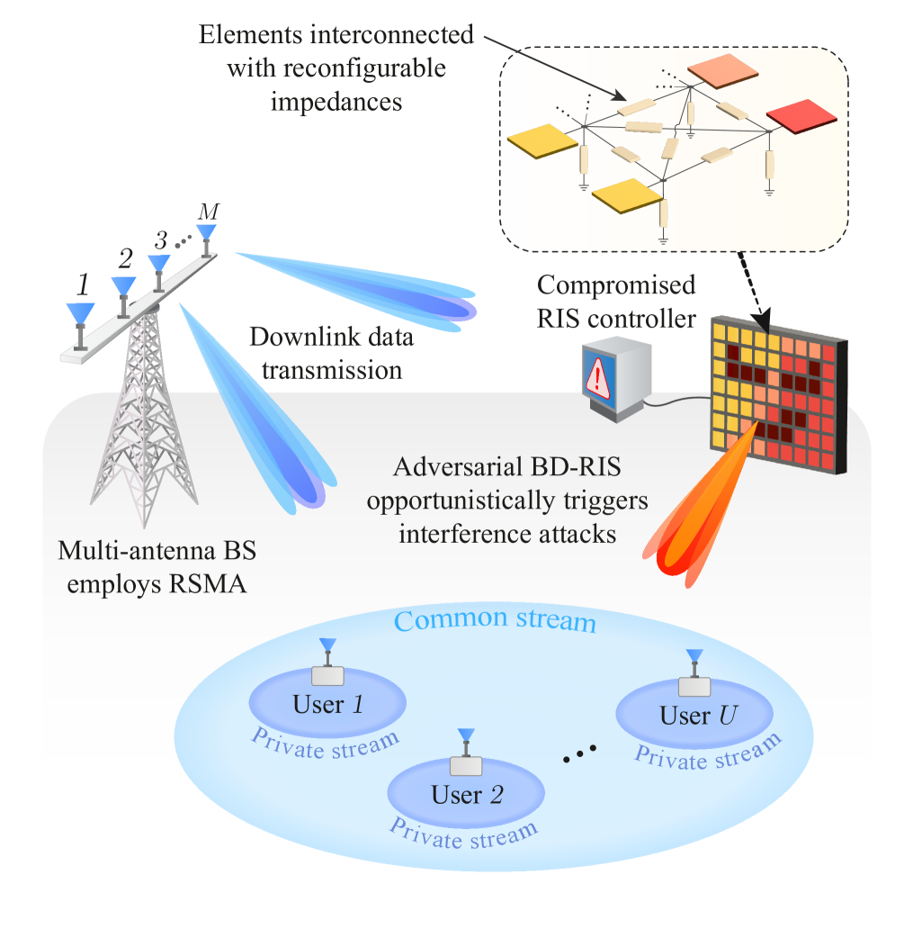
Consider the multi-user MIMO system depicted in Fig. 1, where a BS equipped with a linear array of antennas communicates with single-antenna users, represented by the index set , with the aid of RSMA. The system operates in the presence of an adversarial entity that controls a BD-RIS comprising reflecting elements. The attacker manipulates the BD-RIS to disrupt the channel estimation phase at the BS, configuring it to either absorb incoming pilots [6, 5] (absorption mode) or reflect them randomly [13] (reflective mode). The impact of the mode choice will be investigated in Section V.
Regardless of the RIS’s configuration during uplink training, the attacker generates a new set of reflecting coefficients during the data transmission phase, altering the propagation environment in a manner unknown to the BS. This ensures that the BS operates with corrupted CSI, as its estimates from the training phase do not reflect the RIS’s true, active configuration during data transmission. The discrepancy between estimated and actual CSI reduces the performance of precoders, ultimately generating inter-user interference. Fig. 2 illustrates the overall adversarial protocol.
III-A BD-RIS Architectures
We consider two BD-RIS types, the fully connected and group-connected architectures. In the fully connected BD-RIS, all elements are interconnected through reconfigurable impedances. A fully connected BD-RIS with reflecting elements operates as a -port reciprocal network. The interaction among elements is captured by the scattering matrix , which characterizes the reflection behavior of the system. Energy conservation imposes the constraint , implying that the Frobenius norm satisfies . When the circuit is lossless, the scattering matrix becomes unitary, i.e., . Furthermore, due to the reciprocal nature of the BD-RIS hardware, the symmetry condition must also be satisfied. This property implies that independent coefficients are needed to fully define the entries of .
The group-connected architecture introduces a balance between complexity and performance. In this setup, the reflecting elements are divided into independent groups, each of which forms a fully connected subnetwork. As a result, the overall scattering matrix exhibits a block diagonal structure:
| (1) |
where each submatrix models the signal reflections induced by its corresponding fully connected group, with denoting the number of elements of the th group, such that . Similar to the fully connected case, each submatrix satisfies the conditions and . The number of independent parameters needed to configure each group is, therefore, , in which . From this point onward, we consider lossless reflection models, i.e., we assume and for the fully and group-connected RIS, respectively. The impact of different adversarial strategies is analyzed in the following sections.
III-B RSMA Protocol
In RSMA, the BS partitions each user’s message into common and private parts. Then, all common parts are encoded into a single symbol , while each private part, intended for a specific user , is modulated into a private symbol .
Next, based on the acquired CSI, the BS designs two linear precoders: to deliver the common symbol to all users and to transmit the private symbol to its intended user. Finally, the precoded symbols are superimposed in the power domain, resulting in the transmitted signal:
| (2) |
where and are the power coefficients for the common and private symbols, respectively, satisfying , with denoting the total transmission power. Users receive the superimposed data streams through both the direct link and the adversarial BD-RIS reflections. Thus, the received signal at user is given by:
| (3) |
where , , and model the propagation channels for the direct BS-user link, the BS-RIS link, and the RIS-user link, respectively, and denotes the additive white Gaussian noise with variance .
Each user first decodes the common message, while treating all private signals as interference. Consequently, the SINR (SINR) for the common message at user is:
| (4) |
Since all users must successfully decode the common message, the corresponding achievable rate is dictated by the weakest user, resulting in:
| (5) |
Once the common message is recovered, SIC is applied to remove its contribution from . Thus, the private SINR at user is given by:
| (6) |
The achievable private rate at user is then:
| (7) |
yielding a system sum rate of:
| (8) |
III-C Quantifying Robustness of RSMA
We propose two performance metrics to evaluate the robustness of RSMA against RIS-induced attacks, namely rate degradation and robustness index. The rate degradation quantifies the performance loss caused by an attack, computed as the difference between the baseline performance in a secure environment and the degraded performance during an attack. To this end, the common rate is assumed to be uniformly allocated among the users, i.e., . The overall effective rate for user is then the sum of this portion of the common rate and the individual private rate . The rate degradation experienced by the th user is defined as
| (9) |
where and are the private and common rates observed when the system is under attack, and and are the reference rates in the absence of the attack.
The robustness index complements the rate degradation metric by evaluating the proportion of baseline performance retained during an attack. This normalized metric quantifies the system’s ability to maintain performance under RIS-induced attacks relative to its baseline rates and . The robustness index is defined as
| (10) |
Note that a higher degradation leads to a lower robustness index , such that indicates complete collapse, while corresponds to complete robustness.
III-D CSI Acquisition
Under the assumption of reciprocity, the downlink channels can be estimated at the BS based on uplink measurements from pilot signals transmitted by the users. As explained, during this phase, the attacker can configure the BD-RIS to either absorb or randomly reflect incoming signals. In absorption mode, the pilot signals impinging on the BD-RIS are prevented from reaching the BS. In the random reflective mode, on the other hand, the pilot signals will characterize the BD-RIS-related propagation paths. However, the attacker reconfigures the reflection coefficients in the data transmission phase, making the acquired CSI inaccurate. Thus, in both modes, only imperfect estimates of the channels are accessible to the BS. Adding to the BD-RIS disruptions, other rapid changes in the propagation environment and hardware limitations can also introduce errors in the estimation process. As a result, the direct link estimates will be a combination of the true channels and error components, modeled as:
| (11) |
where is the estimated channel, is a standard complex Gaussian error vector, is a binary coefficient modeling the operation mode of the BD-RIS, with corresponding to absorption mode, and corresponding to reflective mode, and is the error factor for the BS-user link. This model indicates that when , the channel estimate is perfect (i.e., ), while increasing values of imply a larger error component in the estimate. Similarly, when , the uplink CSI is further perturbed by the adversarial BD-RIS link.
As for the attacker, we assume that it can only estimate the channels associated with its BD-RIS, also modeled as imperfect. Specifically, the estimates of the BS-RIS channel matrix and the RIS-user channel vector are given by
| (12) |
and
| (13) |
where and are the corresponding complex Gaussian error components, with and denoting the error factors for the BS-RIS and RIS-user links, respectively.
III-E BS Precoder Design
The private precoder should ensure that the interference observed at user due to transmissions intended for any other user is negligible, i.e., , . This objective is achieved via a regularized zero-forcing approach, which effectively mitigates inter-user interference while balancing noise enhancement. Specifically, the BS first constructs the estimated direct-link channel matrix as
| (14) |
Then, assuming that , which guarantees that has full column rank, the regularized zero-forcing precoding matrix can be computed as
| (15) |
where the regularization factor is given by . The private precoder for user can be readily obtained by
| (16) |
where is the normalization factor for user .
The common precoder should reliably deliver the common message across all users. However, its optimal design is NP-hard, while approximate solutions typically require iterative methods with high computational complexity [27]. To tackle this challenge, we adopt a low-complexity weighted MF (MF) approach as follows:
| (17) |
where the normalization factor guarantees that , and is the weight for the th user. In particular, we prioritize users with weaker channel conditions by setting . This strategy ensures that users experiencing weaker channels receive higher priority in the common precoder design.
III-F Power Allocation
The BS employs a power allocation policy aiming at the maximization of the system sum rate. Given the precoders and for each user , the BS aims to solve the following optimization problem:
| (18a) | ||||
| s.t. | (18b) | |||
| (18c) | ||||
A closed-form optimal solution for (18) is not possible due to the minimum operator in the common rate in (5), i.e., , and the coupled power coefficients, which make the problem non-convex. Instead, we propose a simple but effective approach to approximate our objective.
A meaningful way to perform power allocation is to keep the interference resulting from imperfect CSI approximately at the same level as the noise variance [11]. By doing this, the degradation of users’ data rates can be mitigated. Mathematically, we aim to ensure in the SINR expression for the private stream, , that the interference term . To achieve this goal, we first adopt a uniform power allocation across the private messages, i.e., . Then, it becomes clear that the desired should be inversely proportional to the private inter-user interference . More specifically, for the th user, we should have:
| (19) |
Note that we need to compute an capable of balancing the interference terms across all users in such a way that the system’s sum rate is maximized. Given this goal, we prioritize the user with the best channel conditions, i.e., the one that contributes the most to the sum rate. To this end, we select as reference the best performance indicator given by:
| (20) |
After determining the reference user, we perform the private power allocation as . The common power coefficient is consequently given by:
| (21) |
where the scaling factor adjusts the aggressiveness of the allocation, i.e., a higher increases private power allocation, while a lower reserves more power for the common message.
Thus, the original formulation can be transformed into a simpler version with a single optimization variable, , resulting in the following relaxed power allocation problem:
| (22a) | ||||
| s.t. | (22b) | |||
| (22c) | ||||
| (22d) | ||||
where and denote the common and private rates as functions of . Although the problem remains non-convex due to the minimum operator in the common rate and the nonlinear dependence of the SINRs on , a linear search over within its feasible range provides a practical and efficient method to approximate the solution of (22). Specifically, if is chosen such that , the constraints in (22d) are automatically satisfied.
IV Design of BD-RIS-Induced Attacks
The malicious goal of the attacker is to compute a reflection matrix that degrades the performance of the employed RSMA scheme. In the following subsections, we investigate two approaches to accomplish the goal.
IV-A Random interference attack
A simple yet effective method to degrade the performance of RSMA involves randomly configuring the reflection coefficients of an adversarial RIS to introduce interference, as demonstrated in our previous work with diagonal RIS [6].
Fully connected architecture
As explained, a fully connected RIS requires its reflection matrix to be both symmetric and unitary. To obtain a valid set of reflection coefficients, the adversary starts by creating a random complex matrix and then symmetrizes it, as follows:
| (23) |
However, is generally not unitary. Therefore, we need to project it onto the set of symmetric unitary matrices while respecting its symmetry constraint. To this end, we can rely on the Takagi factorization, which is introduced next.
Property I
Let be a symmetric complex matrix. Then, the Takagi factorization states that there exists a unitary matrix and a diagonal matrix such that , where the diagonal entries of are nonnegative singular values of , called Takagi values, and the columns of are the associated orthonormal Takagi vectors. With Property IV-A, the desired symmetric unitary reflection matrix can be achieved through the following lemma.
Lemma I
Let be a complex symmetric matrix that admits the Takagi factorization . Then, the unique symmetric unitary matrix
| (24) |
minimizes the Frobenius norm and, thus, defines the optimal projection onto the set of symmetric unitary matrices.
Proof: Since is complex symmetric, its Takagi factorization is given by . Any symmetric unitary matrix can be written in the form , where is a diagonal matrix with entries on the unit circle, i.e., , for each diagonal element. The problem of finding the symmetric unitary matrix closest to reduces to choosing such that
| (25) |
is minimized, where the last equality follows from the unitary invariance of the Frobenius norm. Since each diagonal entry is nonnegative, for each the distance is minimized by choosing , as attains its minimum when . Therefore, the optimal projection is given by , yielding , which, clearly, is symmetric since
| (26) |
This completes the proof.
The projection through the Takagi factorization respects both the symmetry and unitary constraints required by the fully connected RIS. For any invertible complex symmetric matrix with distinct singular values, the Takagi factorization can be implemented very efficiently by aligning the phases of the singular vectors computed via the SVD [28].
Group-connected architecture
A similar strategy can be extended for a group-connected RIS architecture. In this case, the attacker must respect the group-wise constraints. Specifically, the reflection matrix should be block-diagonal, comprising independent sub-matrices , for , each one being symmetric and unitary. To generate such a matrix, the adversary follows the same process as for the fully connected RIS, but now for each group. First, it constructs random complex matrices for every group. Then, symmetrized versions are achieved as in (23). Subsequently, the Takagi factorization is computed for each symmetrized matrix, as . The symmetric unitary matrix for the th group is then obtained via the projection , as in Lemma IV-A. Finally, the full reflection matrix is assembled by organizing the sub-matrices into a block-diagonal structure, i.e., .
IV-B Aligned interference attack
A more sophisticated adversarial strategy is to optimize the BD-RIS reflection coefficients to maximize the interference induced at the users. As demonstrated in [6] for conventional RIS systems, if the adversary can acquire partial RIS-associated CSI, it becomes possible to strategically steer the reflected power toward the users. In this subsection, we generalize such optimized attacks to BD-RIS architectures.
Fully connected architecture
Let denote the adversarial weight assigned to user . The malicious fully connected RIS controller aims to maximize the weighted sum of interference powers received at users, subject to unitary and symmetry constraints. Formally, the optimization problem can be formulated as:
| (27a) | ||||
| s.t. | (27b) | |||
| (27c) | ||||
The unitary constraint in (27c) defines a non-convex Stiefel manifold. This, combined with the quadratic dependence of the objective function on , makes the problem challenging to solve optimally. To simplify the original problem, we start by addressing the symmetry constraint in (27b). To this end, we exploit the mathematical structure of symmetric matrices by vectorizing using the concept of duplication matrix.
Property II
For any symmetric matrix , there exists a duplication matrix that maps the half-vectorization of to its full vectorization:
| (28) |
where the duplication matrix is uniquely defined as a sparse matrix with binary entries, given by:
| (29) |
where is a unit vector of length with a single non-zero entry at position , and is a matrix with ones at positions and , and zeros elsewhere [29, Definitions 3.2a and 3.2b].
Property IV-B inherently satisfies the symmetry constraint of the original formulation, allowing us to reformulate the problem in a simpler relaxed version in terms of .
Using the Kronecker product identity , and invoking the duplication matrix relation in (28), we can vectorize the interference channels as:
| (30) |
Then, by defining , and letting denote the reduced vector of unique reflection coefficients, the objective function in (27a) becomes:
| (31) |

Given that , we can define the tall weighted interference matrix: and rewrite the expression in (IV-B) as the convex quadratic objective . This vectorized reformulation automatically satisfies the symmetry constraint in (27b) by construction. On the other hand, the non-convex unitary constraint in (27c) is relaxed with a convex -norm bound , which allow us to formulate a tractable optimization problem:
| (32a) | ||||
| s.t. | (32b) | |||
This relaxed problem (32) constitutes a QCQP, whose optimal solution is the dominant right singular vector of the matrix . More specifically, by recalling the SVD, we can express , where contains the right singular vectors. Then, the optimal solution to the relaxed problem is given by , thus satisfying , and the corresponding relaxed BD-RIS matrix is obtained by:
| (33) |
However, generally violates the unitary constraint, i.e., . To enforce this, we project onto the closest unitary matrix via the Takagi factorization explained in Property IV-A, i.e., , allowing us to compute
| (34) |
where, according to Lemma IV-A, the symmetry is preserved.
Group-connected architecture
The aligned interference attack is now generalized for the group-connected architecture. Let us consider a BD-RIS partitioned into independent groups, i.e., , with each block satisfying and . Then, the optimized adversary attack strategy can be formulated as:
| (35a) | ||||
| s.t. | (35b) | |||
| (35c) | ||||
| (35d) | ||||
To address problem 35, the first step is to decompose the global channel matrices into group-specific subchannels. To this end, let denote the index subset of RIS elements associated with group , with . Then, the BS-RIS subchannel for group can be expressed as
| (36) |
while the RIS-user subchannel becomes
| (37) |
Next, following Property IV-B, we construct a duplication matrix to vectorize the symmetric matrix as for each group, where denotes the th reduced coefficient vector. We also define , and represent the set of RIS groups by . Then, we rewrite the adversary objective as follows:
| (38) |
To further simplify, we introduce a global stacked vector:
| (39) |
and define, for each user , the block row matrix:
| (40) |
Now, the summation related to the groups can be written as a single matrix structure, as follows:
| (41) |
Then, we define a global matrix stacking all matrices:
| (42) |
This allows us to write the summation in (IV-B) in its matrix-equivalent form, resulting in the final compact problem:
| (43a) | ||||
| s.t. | (43b) | |||
The solution to (43) can be obtained with the aid of the SVD, similarly to the problem (32). More specifically, we can decompose and achieve the desired solution by computing , where is the dominant right singular vector of , i.e., the first column of . Finally, by letting denote the index subset corresponding to the th reduced coefficient vector, with , the relaxed coefficients for each independent RIS group can be obtained as , and , . Recalling Property IV-A, we compute the Takagi factorization and project each onto its closest unitary matrix, as follows:
| (44) |
Finally, the full BD-RIS reflection matrix is constructed as .
V Numerical Results
In this section, we evaluate the impact of BD-RIS-induced attacks under both random and optimized strategies and investigate RSMA’s ability to maintain performance under adversarial conditions. We investigate the degradations induced by fully connected, group-connected, and conventional single-connect RIS architectures and provide a comprehensive performance comparison with SDMA.
The simulation setup comprises: (i) a BS equipped with transmit antennas positioned at the origin, (ii) three users located at distances of m, m, and m from the BS, with corresponding azimuth angles of , , and , and (iii) the adversarial RIS deployed a distance m apart from the BS with an azimuth angle of . Simulations are performed for various numbers of reflecting elements, with the group-connected RIS architecture configured as . All links follow a power-law path loss model with , where represents the corresponding distance. In particular, the distance from the RIS to the th user can be obtained by , resulting in the distances m, m, and m. Moreover, the user weights for Algorithms 1 and 2 are set uniformly as , the noise variance is set to dB, and the SDMA scheme employs uniform power allocation with regularized zero-forcing precoders.
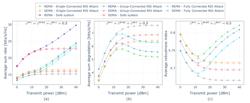
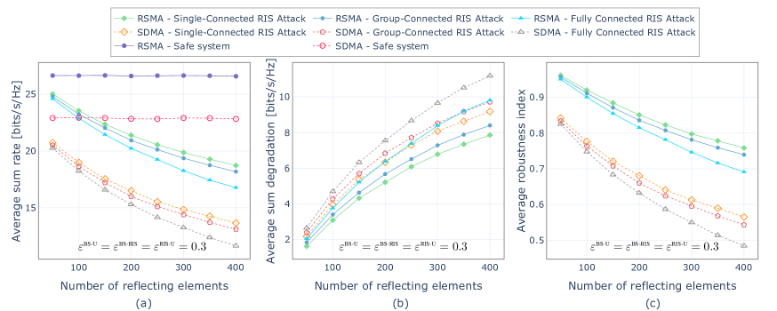
Fig. 3 investigates the impact of the RIS operation mode during the training phase on the RSMA average sum rate for different RIS architectures with reflecting elements, under both perfect and imperfect CSI. It can be seen in all subfigures that using reflective mode during uplink training leads to lower average sum rates. This applies to both perfect CSI, Figs. 3(a) and 3(c), and imperfect CSI cases, Figs. 3(b) and 3(d). This training mode choice significantly boosts the degradation potential for all RIS architectures, but the benefit for the attacker is largest when using BD-RIS. Even under random interference attacks, group-connected and fully connected architectures cause significantly more degradation than a single-connected RIS if the reflective mode training is employed, which can be observed in both Figs. 3(a) and 3(b). The degradations under aligned interference attacks in Fig. 3(c) are even greater, with the fully connected RIS reducing the sum rate to approximately bits/s/Hz at dBm, which is significantly lower than the bits/s/Hz achieved by the single-connected RIS employing the reflective training mode. This outcome suggests that operating the RIS in reflective mode during pilot transmission leads to more severe errors in the legitimate system’s channel estimation. These errors, in turn, degrade the effectiveness of the private precoders and increase the impact of subsequent attacks, particularly for BD-RIS architectures due to their superior radiation efficiency. It is also worth noting that the results under imperfect CSI in Figs. 3(b) and 3(d) offer a glimpse into an important RSMA feature: its inherent robustness and potential for attack recovery thanks to the adaptive power allocation described in Section III-F.
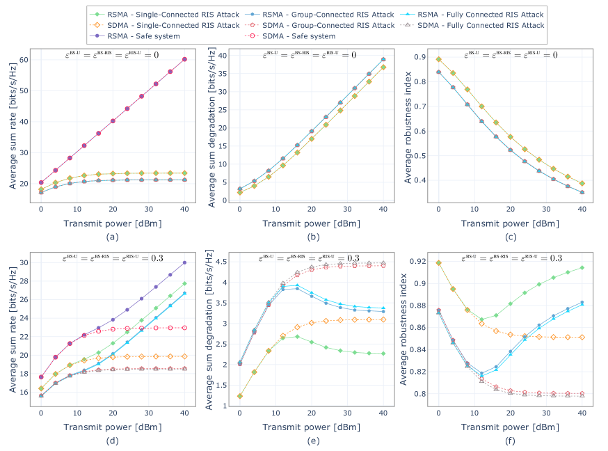
Given that operating in reflective mode during uplink pilot training leads to more severe degradation, we adopt this mode in Fig. 4 and subsequent results. Fig. 4 compares the performance of RSMA and SDMA under random interference attacks versus varying transmit power levels. Figs. 4(a)–4(c) depict the ideal scenario of perfect CSI at both the BS and the attacker. Fig. 4(a) shows that attacks via any RIS architecture force both RSMA and SDMA sum rate curves to saturate at high transmit powers, a behavior absent in the safe system baseline. Moreover, since RSMA reduces to SDMA under perfect CSI conditions, the two schemes exhibit identical performance under both safe and attack scenarios, corroborating intuition and previously reported results [9]. Fig. 4(a) also reinforces why an attacker might choose a BD-RIS: group‐connected and fully‐connected architectures induce larger performance degradations (saturating near 21 ) than single‐connected RIS (saturating near 23 ). This trend also manifests in Fig. 4(b), where the average sum-rate degradation, defined in (9), is consistently higher for BD-RIS attacks. In Fig. 4(c), the average robustness index further confirms this behavior, with single-connected RIS attacks achieving approximately at 40 dBm versus for the BD-RIS at the same power level.
Shifting the focus to the imperfect CSI case in Figs. 4(d)–4(f), the performance dynamics change considerably. Fig. 4(d) shows the average sum rate, highlighting two key aspects: first, RSMA now consistently achieves a significantly higher sum rate than SDMA under all attack scenarios, demonstrating its inherent robustness when channel knowledge is imperfect. Second, the performance difference due to the attacking RIS architecture becomes more pronounced. Attacks from the fully connected RIS yield the lowest sum rate, followed by the group-connected, with the single-connected RIS being the least detrimental. Fig. 4(e) shows the corresponding average sum‐rate degradation and confirms that RSMA is less affected than SDMA across all RIS architectures, exhibiting significantly lower sum-rate degradation values. It is also reinforced that RSMA can partially recover from the attacks. The sum-rate degradation for RSMA peaks near 12 dBm and then decreases slightly as the transmit power gets higher – a trend not observed with SDMA. This behavior results in higher robustness index values for RSMA when transmit powers are greater than 12 dBm in Fig. 4(f). Furthermore, the robustness index is highest for single-connected and lowest for fully connected attacks.


Fig. 5 delves deeper into the impact of aligned interference attacks under imperfect CSI. As can be seen, the proposed optimized attack is highly effective, leading to more severe performance degradation on both RSMA and SDMA across the considered RIS architectures compared to the random interference in Fig. 4. For instance, RSMA under attack now struggles to exceed 24 even at high transmit power in Fig. 5(a), compared to nearly 28 under random attacks (Fig. 4(d)). SDMA, in particular, suffers drastically, with its sum-rate barely increasing with transmit power and remaining below 17 across all RIS architectures. Fig. 5(b) shows the average sum-rate degradation. Compared to random attacks (Fig. 4(e)), the degradation values are significantly higher for both schemes. RSMA still exhibits its characteristic robustness, with its degradation again peaking (now, around 15 dBm) before decreasing, indicating its mitigation capabilities even against these optimized attacks. In contrast, SDMA shows higher degradation levels that saturate at high transmit powers, highlighting its inability to recover from the attacks. Consequently, in Fig. 5(c), RSMA achieves considerably higher robustness index values than SDMA, especially for transmit powers above 10 dBm.
Fig. 6 analyzes the impact of the adversarial RIS size on system performance under aligned interference attacks, considering a fixed transmit power of 30 dBm and imperfect CSI. The detrimental effect of increasing the number of reflecting elements is markedly amplified under aligned attacks. As shown in Fig. 6(a), the sum rate of SDMA collapses at larger , while the decline of RSMA is less severe. This is further evidenced in Fig. 6(b), where SDMA incurs substantially higher sum-rate degradation, and in Fig. 6(c), where the difference in robustness between RSMA and SDMA becomes particularly pronounced as grows, highlighting RSMA’s superior ability to cope with harmful interference. The relative impact of different RIS architectures follows the established trend, with BD-RIS inflicting the most damage. However, the aligned attack strategy enhances the effectiveness of all architectures, such that even attacks via single-connected RISs cause substantial performance loss, particularly for large . We can also see that the performance curves for the different architectures are more distinctly separated across the range of , confirming that the architectural choice of the attacking RIS is a significant factor, even more so under optimized attacks.
Fig. 7 presents the system response to aligned interference attacks versus varying channel estimation errors, assuming the error is uniform across all links, i.e., . As the channel estimation error increases, the safe system sum rate for both RSMA and SDMA decreases substantially. However, because of the smart power splitting of RSMA, it achieves superior performance throughout the error range. Under attack, Fig. 7(a) reveals that SDMA’s sum rate monotonically decreases with increasing . On the other hand, RSMA’s sum rate under attack exhibits a slight initial increase for small before decreasing, suggesting its interference management adapts well to low to moderate channel error levels even under attack. The average sum-rate degradation in Fig. 7(b) shows a steep decrease as increases for all attacked scenarios. This is attributed to the drop in the safe system’s performance caused by imperfect CSI, which reduces the absolute difference between the safe and attacked performance levels. As for the average robustness index in Fig. 7(c), SDMA’s curves under attack start at its highest value at and decrease steadily as increases, dropping below at high error levels. In contrast, RSMA displays a different trend, such that its robustness increases with lower values of , peaks around , and then declines, although remaining significantly above SDMA’s robustness for all .
Fig. 8 isolates the effect of channel estimation errors specific to the RIS-related links () under aligned interference attacks, with the BS-User link error fixed at . As the error increases, the performance of both SDMA and RSMA under attack improves. For instance, Figs. 8(a), (b), and (c) respectively show a slightly increasing average sum rate, a decreasing average sum-rate degradation, and an increasing average robustness index. This behavior comes from the fact that higher estimation errors () lead to less accurate RIS configurations, resulting in less effectively aligned interference. Across all values of , RSMA maintains significantly higher sum rates and robustness, with lower degradation than SDMA. Furthermore, the relative impact of the RIS architectures persists despite the attacker’s imperfect channel knowledge, with the fully connected RIS consistently delivering the strongest attacks.
VI Conclusions
This paper has investigated the robustness of RSMA-based multi-user MIMO systems to adversarial attacks induced by BD-RIS. Two effective attack strategies were described and studied: random and aligned interference. For each, novel algorithms were proposed to generate valid reflection coefficients respecting the architectural BD-RIS constraints. Extensive simulations revealed that RSMA demonstrated significantly greater robustness to these attacks than the benchmark SDMA scheme, especially under imperfect CSI. Moreover, BD-RIS significantly enhances adversarial efficacy compared to conventional RIS, with particularly severe performance degradation observed when the BD-RIS manipulates the uplink training phase via reflective operation. Future work should expand this analysis and investigate the adversarial potential of multi-sector BD-RIS and its non-reciprocal architectures. The development of robust countermeasures against such threats is another crucial direction.
Acknowledgments
This work was supported by the Commonwealth Cyber Initiative (cyberinitiative.org) in Virginia, US, an investment to advance cyber R&D, innovation, and workforce development, the National Science Foundation under grants no. 2326599 and 231879, and the Research Council of Finland through the 6G-ConCoRSe project (grant no. 359850) and the 6G Flagship programme (grant no. 369116).
References
- [1] B. Lyu, D. T. Hoang, S. Gong, D. Niyato, and D. I. Kim, “IRS-based wireless jamming attacks: When jammers can attack without power,” IEEE Wireless Commun. Lett., vol. 9, no. 10, pp. 1663–1667, 2020.
- [2] Y. Wang, H. Lu, D. Zhao, Y. Deng, and A. Nallanathan, “Wireless communication in the presence of illegal reconfigurable intelligent surface: Signal leakage and interference attack,” IEEE Wireless Commun. Mag., vol. 29, no. 3, pp. 131–138, 2022.
- [3] P. Staat, H. Elders-Boll, M. Heinrichs, C. Zenger, and C. Paar, “Mirror, mirror on the wall: Wireless environment reconfiguration attacks based on fast software-controlled surfaces,” in Proc. Asia Conf. on Computer and Communications Security, 2022, pp. 208–221.
- [4] H. Alakoca, M. Namdar, S. Aldirmaz-Colak, M. Basaran, A. Basgumus, L. Durak-Ata, and H. Yanikomeroglu, “Metasurface Manipulation Attacks: Potential Security Threats of RIS-Aided 6G Communications,” IEEE Commun. Mag., vol. 61, no. 1, pp. 24–30, 2023.
- [5] H. Huang, Y. Zhang, H. Zhang, Y. Cai, A. L. Swindlehurst, and Z. Han, “Disco intelligent reflecting surfaces: Active channel aging for fully-passive jamming attacks,” IEEE Trans. Wireless Commun., vol. 23, no. 1, pp. 806–819, 2024.
- [6] A. S. de Sena, J. Kibilda, N. H. Mahmood, A. Gomes, and M. Latva-aho, “Malicious RIS versus massive MIMO: Securing multiple access against RIS-based jamming attacks,” IEEE Wireless Commun. Lett., vol. 13, no. 4, pp. 989–993, 2024.
- [7] H. Wang, Z. Han, and A. L. Swindlehurst, “Channel Reciprocity Attacks Using Intelligent Surfaces With Non-Diagonal Phase Shifts,” IEEE Open Journal of the Communications Society, vol. 5, pp. 1469–1485, 2024.
- [8] S. Rivetti, O. T. Demir, E. Bjornson, and M. Skoglund, “Malicious Reconfigurable Intelligent Surfaces: How Impactful Can Destructive Beamforming be?” IEEE Wireless Commun. Lett., vol. 13, no. 7, pp. 1918–1922, 2024.
- [9] A. S. de Sena, A. Gomes, J. Kibilda, N. H. Mahmood, L. A. DaSilva, and M. Latva-aho, “Malicious RIS Meets RSMA: Unveiling the Robustness of Rate Splitting to RIS-Induced Attacks,” IEEE GlobeCom (GlobeCom), pp. 3576–3581, 2024.
- [10] A. S. de Sena, P. H. J. Nardelli, D. B. da Costa, P. Popovski, and C. B. Papadias, “Rate-splitting multiple access and its interplay with intelligent reflecting surfaces,” IEEE Commun. Mag., vol. 60, no. 7, pp. 52–57, 2022.
- [11] B. Clerckx, Y. Mao, E. A. Jorswieck, J. Yuan, D. J. Love, E. Erkip, and D. Niyato, “A Primer on Rate-Splitting Multiple Access: Tutorial, Myths, and Frequently Asked Questions,” IEEE J. Sel. Areas Commun., vol. 41, no. 5, pp. 1265–1308, 2023.
- [12] H. Li, S. Shen, M. Nerini, and B. Clerckx, “Reconfigurable intelligent surfaces 2.0: Beyond diagonal phase shift matrices,” IEEE Commun. Mag., vol. 62, no. 3, pp. 102–108, 2023.
- [13] H. Huang, L. Dai, H. Zhang, C. Zhang, Z. Tian, Y. Cai, A. L. Swindlehurst, and Z. Han, “DISCO Might Not Be Funky: Random Intelligent Reflective Surface Configurations That Attack,” IEEE Wireless Commun. Mag., vol. 31, no. 5, pp. 76–82, 2024.
- [14] A. Gomes, A. S. de Sena, N. H. Mahmood, M. Latva-aho, L. A. DaSilva, and J. Kibiłda, “Beam Management Manipulation with Adversarial Reconfigurable Intelligent Surfaces,” in IEEE GlobeCom, 2024, pp. 3231–3236.
- [15] G. Li, P. Staat, H. Li, M. Heinrichs, C. Zenger, R. Kronberger, H. Elders-Boll, C. Paar, and A. Hu, “RIS-Jamming: Breaking Key Consistency in Channel Reciprocity-Based Key Generation,” IEEE Trans. Inf. Forensics Security, vol. 19, pp. 5090–5105, 2024.
- [16] H. Wang, J. Nossek, and A. L. Swindlehurst, “Beyond-Diagonal RIS Attacks on Physical Layer Key Generation,” in IEEE International Workshop on Signal Processing Advances in Wireless Communications (SPAWC), 2024, pp. 946–950.
- [17] H. Huang, H. Zhang, W. Mei, J. Li, Y. Cai, A. L. Swindlehurst, and Z. Han, “Integrated Sensing and Communication Under DISCO Physical-Layer Jamming Attacks,” IEEE Wireless Commun. Lett., vol. 13, no. 11, pp. 3044–3048, 2024.
- [18] S. Rivetti, O. T. Demir, E. Bjornson, and M. Skoglund, “Destructive and constructive RIS beamforming in an ISAC-multi-user MIMO network,” arXiv preprint arXiv:2404.11314, 2024.
- [19] G. Zhou, Y. Mao, and B. Clerckx, “Rate-splitting multiple access for multi-antenna downlink communication systems: Spectral and energy efficiency tradeoff,” IEEE Trans. Wireless Commun., vol. 21, no. 7, pp. 4816–4828, 2022.
- [20] H. Lu, X. Xie, Z. Shi, H. Lei, N. Zhao, and J. Cai, “Outage Performance of Uplink Rate Splitting Multiple Access With Randomly Deployed Users,” IEEE Trans. Wireless Commun., vol. 23, no. 2, pp. 1308–1326, 2024.
- [21] Y. Xu, Y. Mao, O. Dizdar, and B. Clerckx, “Rate-Splitting Multiple Access With Finite Blocklength for Short-Packet and Low-Latency Downlink Communications,” IEEE Trans. Veh. Technol., vol. 71, no. 11, pp. 12 333–12 337, 2022.
- [22] S. Pala, M. Katwe, K. Singh, B. Clerckx, and C.-P. Li, “Spectral-Efficient RIS-Aided RSMA URLLC: Toward Mobile Broadband Reliable Low Latency Communication (mBRLLC) System,” IEEE Trans. Wireless Commun., vol. 23, no. 4, pp. 3507–3524, 2024.
- [23] O. Dizdar, Y. Mao, and B. Clerckx, “Rate-Splitting Multiple Access to Mitigate the Curse of Mobility in (Massive) MIMO Networks,” IEEE Trans. Commun. Technol., vol. 69, no. 10, pp. 6765–6780, 2021.
- [24] R.-J. Reifert, S. Roth, A. A. Ahmad, and A. Sezgin, “Comeback kid: Resilience for mixed-critical wireless network resource management,” IEEE Trans. Veh. Technol., vol. 72, no. 12, pp. 16 177–16 194, 2023.
- [25] H. Wang, Z. Han, and A. L. Swindlehurst, “Non-Diagonal RIS Empowered Channel Reciprocity Attacks on TDD-Based Wireless Systems,” in IEEE International Conference on Communications (ICC), 2024, pp. 127–132.
- [26] H. Huang, H. Zhang, J. Yuan, L. Sun, Y. Wang, W. Mei, B. Di, Y. Cai, and Z. Han, “Disco Intelligent Omni-Surfaces: 360-degree Fully-Passive Jamming Attacks,” arXiv preprint arXiv:2411.12985, 2024.
- [27] A. Konar and N. D. Sidiropoulos, “Fast approximation algorithms for a class of non-convex QCQP problems using first-order methods,” IEEE Trans. Signal Process., vol. 65, no. 13, pp. 3494–3509, 2017.
- [28] L. Dieci, A. Papini, and A. Pugliese, “Takagi Factorization of Matrices Depending on Parameters and Locating Degeneracies of Singular Values,” SIAM Journal on Matrix Analysis and Applications, vol. 43, no. 3, pp. 1148–1161, 2022.
- [29] J. R. Magnus and H. Neudecker, “The Elimination Matrix: Some Lemmas and Applications,” SIAM Journal on Algebraic Discrete Methods, vol. 1, no. 4, pp. 422–449, 1980.