UMArm: Untethered, Modular, Wearable, Soft Pneumatic Arm
Abstract
Robotic arms are essential to modern industries, however, their adaptability to unstructured environments remains limited. Soft robotic arms, particularly those actuated pneumatically, offer greater adaptability in unstructured environments and enhanced safety for human-robot interaction. However, current pneumatic soft arms are constrained by limited degrees of freedom, precision, payload capacity, and reliance on bulky external pressure regulators. In this work, a novel pneumatically driven rigid-soft hybrid arm, “UMArm”, is presented. The shortcomings of pneumatically actuated soft arms are addressed by densely integrating high-force-to-weight-ratio, self-regulated McKibben actuators onto a lightweight rigid spine structure. The modified McKibben actuators incorporate valves and controllers directly inside, eliminating the need for individual pressure lines and external regulators, significantly reducing system weight and complexity. Full untethered operation, high payload capacity, precision, and directionally tunable compliance are achieved by the UMArm. Portability is demonstrated through a wearable assistive arm experiment, and versatility is showcased by reconfiguring the system into an inchworm robot. The results of this work show that the high-degree-of-freedom, external-regulator-free pneumatically driven arm systems like the UMArm possess great potential for real-world unstructured environments.
Index Terms:
Soft robotic arms, Pneumatic actuators, Untethered systems, Wearable deviceI Introduction
Robotic arms are essential components in modern industries. Rigid robotic arms can operate with great precision, speed, and payload capacity, making them ideal for highly structured environments like factories [1, 2, 3]. However, their application in unstructured real-world environments remains limited due to their lack of compliance. In unstructured environments, compliance is crucial for safe interaction and effective handling of unexpected disturbances. Compliance can be achieved either by structure or by control. Rigid robots can simulate compliance through control, but it requires the coordinated control of all actuators, and will be limited by controller bandwidth and sensor latency. Without full-body compliance, rigid arms have to operate on highly precise and low-latency spatial information—a requirement that is difficult to satisfy in unstructured environments [4, 5]. Consequently, rigid arms can cause damage to target objects, nearby humans, or the robot itself [6, 7, 8].
Unlike their rigid counterparts, soft robotic arms have structural compliance. They are capable of mitigating external disturbances and compensating for misalignment through elastic deformation of their structure, making them more suitable for operation in unstructured environments [9, 10, 11]. Their inherent compliance also ensures safety in physical human-robot interaction, enabling use cases such as daily assistance and elder care [12, 13].
A variety of soft actuation strategies have been explored to enable compliance and safety in unstructured environments. HASEL actuators achieve high strain and power output via electrohydraulic zipping, enabling fast, modular actuation; however, their high-voltage requirements and structural fragility pose challenges for unstructured deployment [14]. Shape memory alloy (SMA)-driven soft actuators offer compact and lightweight actuation with high power-to-weight ratios and low voltage requirements but suffer from slow thermal response, nonlinear behavior, and sensitivity to ambient temperature—factors that hinder precise control [15]. Hydraulic soft actuators provide high force output[16], yet their practicality is limited by their bulky fluidic components and slow responses. Tendon-driven designs have also gained attention, offering enhanced workspaces and tunable compliance through mechanisms like trimmed helicoids [17], but these systems remain vulnerable to friction, slack, and lack robustness under dynamic conditions [17, 15].
Among various soft actuation strategies, pneumatic actuators are promising due to their smooth, continuous deformation, high force-to-weight ratio, and compliance in every direction. Unlike cable-driven mechanisms, pneumatic actuators do not require complex cable routing, which simplifies design and thus enhances reliability. Compared to dielectric elastomers, HASEL actuators, and shape memory alloys, pneumatic actuators offer a more practical path toward building human-arm-scale systems that avoids the need for high-voltage operation, complex material packaging, or thermally limited cycle rates. These properties, combined with their resilience to impact, ease of fabrication, and cost-effectiveness, make pneumatic actuators particularly well-suited for building robot arms for deploying into real-world, unstructured environments [18, 19, 20, 21, 22, 23].
Although pneumatically actuated soft arms have desirable characteristics, certain drawbacks limit their performance. Firstly, although many pneumatic soft arms are lightweight, they require bulky external pressure regulators [24]. The cumbersome external hardware limits their portability. Secondly, high dexterity pneumatic soft arms need many independently actuated degrees of freedom (DoF), but the centralized, external regulating scheme makes it difficult to increase independent DoFs. This is because adding independently controlled pneumatic actuators requires extra external regulators and more tubing running from the actuators to the external regulators. Large amounts of tubing will introduce extra weight, thereby affecting the payload capacity of the arm. At the same time, long thin tubes increase fluidic resistance, causing pressure to propagate more slowly from the regulator to the actuator, affecting pressure control performance [25]. Thirdly, structurally soft pneumatic arms might suffer from uncontrolled compliant degrees of freedom (DoF). Under heavy load, they might buckle at unwanted positions, affecting precision and payload capacity [26]. Moreover, robots might oscillate at the uncontrolled compliant joints when given aggressive control inputs [27].
Researchers have explored various pneumatic soft arm architectures to address common limitations. Continuum soft pneumatic arms [28, 29, 30, 31, 20, 32], which offer infinite degrees of freedom (DoFs) and desirable traits such as flexibility and low cost, often using silicone rubber or origami structures. However, their uncontrolled DoFs reduce precision and payload capacity. To overcome this, rigid-soft hybrid arms have been developed, combining rigid bones and joints with soft pneumatic actuators. This reduces uncontrolled compliance by limiting it to the joints. For instance, Ohta et al. created a rigid-bone arm actuated by McKibben actuators [33]. While lightweight and accurate, only five of its seven DoFs are actuated by McKibbens, and the low contraction ratio of McKibben actuators introduces a tradeoff between joint force and range of motion – placing the actuator attachment point closer to the joint would increase range of motion, but decrease the length of the force lever arm, and vice versa. Therefore, McKibben actuator-based arms with limited DoFs find it difficult to achieve both large payload capacity and workspace size. Adding more independently controlled, stronger actuators could help, but will increase design complexity due to the extra tubing and regulators required. Bruder et al. addressed payload limitations with antagonistic stiffening in a McKibben-based soft arm [34], improving force transmission. However, each segment uses only one actuator for stiffening, requiring all DoFs in the segment to stiffen together, which limits motion during stiffening. Origami-based hybrid designs are also promising. Liu et al. used water bomb origami in a rigid-soft arm [35], achieving high payload capacity. Yet, the locking mechanism only engages when fully extended, limiting its practicality. Oh et al. used origami bellows as actuators [36], resulting in strong force output and motion range, but limited DoFs and scaling challenges due to bellow size and pressure constraints. Other approaches focus on high-density actuators. Zhou et al. developed a compact segment with many independently controlled rubber bellows [37], achieving excellent dexterity and precision. However, like all existing designs, it relies on bulky, centralized regulators that reduce portability and hinder use in unstructured environments. In summary, while existing designs address some challenges, none fully overcome all limitations of pneumatic soft arms in unstructured environments. A new design approach is needed.
To address the key limitations of existing pneumatically driven soft arms – namely, limited precision, payload capacity, and reliance on bulky external regulators – we propose a new design approach that integrates pressure regulation directly into the actuators. Building on a recent work [25], where the authors introduced the valve-embedded McKibben actuator (VEMA), we present UMArm, a pneumatically driven rigid-soft hybrid robotic arm designed for high performance in unstructured environments.
UMArm is a highly capable robotic arm with 24 independently controlled actuators, untethered operation capability, and the ability to lift a 3 kg payload while weighing only 1.15 kg. Its design combines embedded actuator pressure regulation, a dense arrangement of independent actuators, tunable stiffness, and rigid structural support within a portable form factor. Specifically, this work introduces three key hardware innovations:
-
•
Integrated pneumatic-power-communication bus architecture, enabling dozens of independently controlled pneumatic actuators to be operated in parallel with shared tubing and wiring.
-
•
High-density actuator arrangement that accommodates eight VEMAs per arm segment, allowing for multidirectional antagonistic stiffening at every joint.
-
•
Lightweight articulated rigid spine structure for efficient force transmission despite a large range of motion.
UMArm’s design directly addresses the core challenges faced by pneumatically driven soft arms. First, it enhances portability and removes dependence on bulky external regulators by employing VEMAs, which integrate local pressure control within each actuator. This distributed control eliminates the need for centralized pneumatic hardware and individual pneumatic lines for each actuator. Second, the pneumatic-power-communication bus architecture, combined with the dense arrangement of VEMAs, allows for a high number of independently actuated degrees of freedom (DoFs). This enables precise, fine-grained control and supports directional compliance. Third, the rigid spine is engineered to withstand the significant forces produced by antagonistic actuator pairs during stiffening, resulting in improved force transmission and a high strength-to-weight ratio. Finally, by incorporating antagonistic actuation at each joint, UMArm provides tunable compliance. This enables the arm to selectively modulate stiffness in different directions, improving adaptability and precision when interacting with complex or unpredictable environments.
To demonstrate UMArm’s effectiveness, we experimentally validated its ability to perform tasks that have traditionally been challenging for pneumatically driven soft arms. First, a series of experiments is conducted to demonstrate UMArm’s precision, high payload capacity, and untethered capability. The precision of UMArm is showcased through a way point tracking experiment, where it achieves to track given way points with 2.6mm RMSE. Then, its weight-lifting ability is tested with up to 3 kg of payload. Additionally, we tested its untethered operation capability by powering it with a portable compressed air tank, which successfully sustained the UMArm for 12 minutes at full capacity. Second, through the use of antagonistic stiffening, UMArm achieves high-precision manipulation. It can stack three small objects with great consistency. Moreover, the antagonistic stiffness is independently controlled for each joint, granting UMArm the ability to perform directional compliance control. We have shown that the UMArm can structurally stiffen in one direction while remaining soft in another, enabling more adaptive interactions. Third, we demonstrate that UMArm can be worn and used on worksites, highlighting both its portability and its capability of using its compliant structure to compensate for misalignment and disturbances. Finally, to showcase its versatility, we added legs between arm segments, transforming UMArm into an untethered inchworm robot, further broadening its potential application space.
II Design
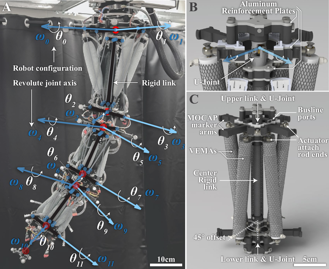
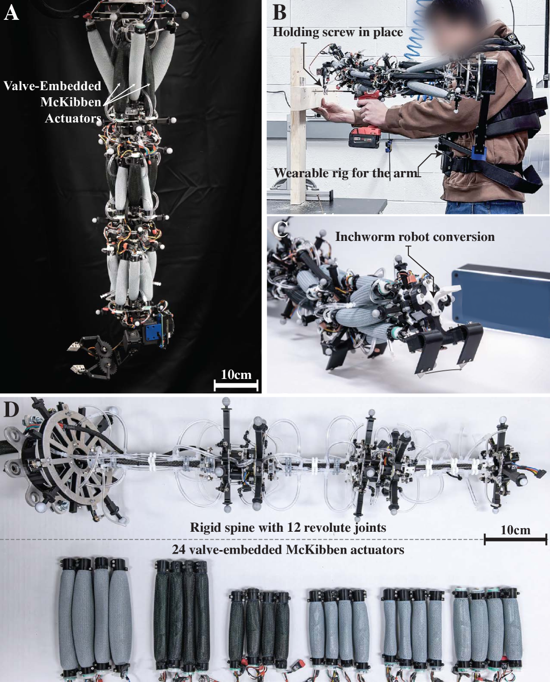
In designing the UMArm, we aim to explore a method for scaling up the number of independently controlled actuators within a compact system and to determine what performance gains can be achieved through this approach. UMArm is a hybrid rigid-soft arm. UMArm has a rigid spine driven by soft actuators. The rigidity of a spine significantly improves precision and force output, and the soft actuators maintain the structural compliance of the arm. As illustrated in figure 1D, the UMArm consists of three structurally identical spine segments. Each segment has three rigid-body links — an upper plate, a central rod, and a lower plate — connected in series by two universal joints (U-joints). We chose to use U-joints because they are lightweight and have no backlash. The U-joints also restrict z-axis rotation, which is helpful since we do not have actuators to control that degree of freedom. Each U-joint (Fig. 2B), can be simplified as 2 revolute joints with perpendicular axes. As a result, the UMArm can be seen as a robot with 12 revolute joints, assuming that the links between the two joints are rigid.
To let the system accommodate a greater number of independently controlled actuators, we employ the valve-embedded McKibben actuator (VEMA) that features self-pressure regulating [25]. All VEMAs are connected to the shared constant pressure source, which can be a single pressurized tube with a larger diameter that runs through the arm. Therefore, we eliminated the need for individual long tubing that connects each actuator to its external regulator. Compared to using the thin, long individual tubing for every actuator, the use of shared, larger-diameter tubing will decrease the whole system’s weight and complexity and improve pressure control performance by lowering the pneumatic friction. Also, after establishing the shared pressure line, adding more actuators to the arm would need very little additional hardware, making it possible to scale up the number of actuators in our arm. Under this pressure bus line architecture, we have installed 24 individually controlled VEMAs to the arm. Having such a large number of independently controlled actuators gives us the ability to simultaneously control the joint’s angle and structural stiffness for all 12 joints. Structural stiffness control is achieved through antagonistically placing the actuators for each joint. In the following sections of this manuscript, we will demonstrate that being able to control the stiffness of every joint can improve payload capacity, arm precision, and safety while working around humans.
Limited joint range of motion remains a significant challenge for McKibben-based antagonistic stiffening arms. McKibben actuators can only contract by approximately 34% [38]. When used to drive a revolute joint on an arm, one can increase the range of motion of the joint by decreasing the length of the lever arm, but at the cost of decreasing torque output. UMArm can address this limitation by incorporating more joints within the same arm length, because although each joint would have a small range of motion (but larger force), the net range of motion across all the joints can remain large. Figure 2C shows the actuator placement. We integrated 8 VEMAs into one arm segment. Four VEMAs control the two joint angles between the upper link and the center link. In the resting state, these actuators are angled toward the center. This ensures better force output at a larger joint angle, where the contracted actuator will have better alignment with the force lever arm, and the elongated actuator will generate larger forces at a given pressure, in accordance with the McKibben model in [39]. The gap between the four upper VEMAs can accommodate another group of four VEMAs that drive the joint angles between the center rod and lower plate. As shown in Fig.2C, the lower group is reversed and rotated by 45° to prevent interference while operating. This configuration of VEMA placement efficiently utilizes the space, thus increasing the density of joints, which, as a result, effectively improves the overall range of motion. The UMArm is built with 3 of these segments. The base segment is designed to withstand more load. It has a longer force lever arm for the VEMAs and uses a variant of VEMA with a larger diameter, which will output larger force compared to the smaller diameter VEMAs at the same length and pressure.
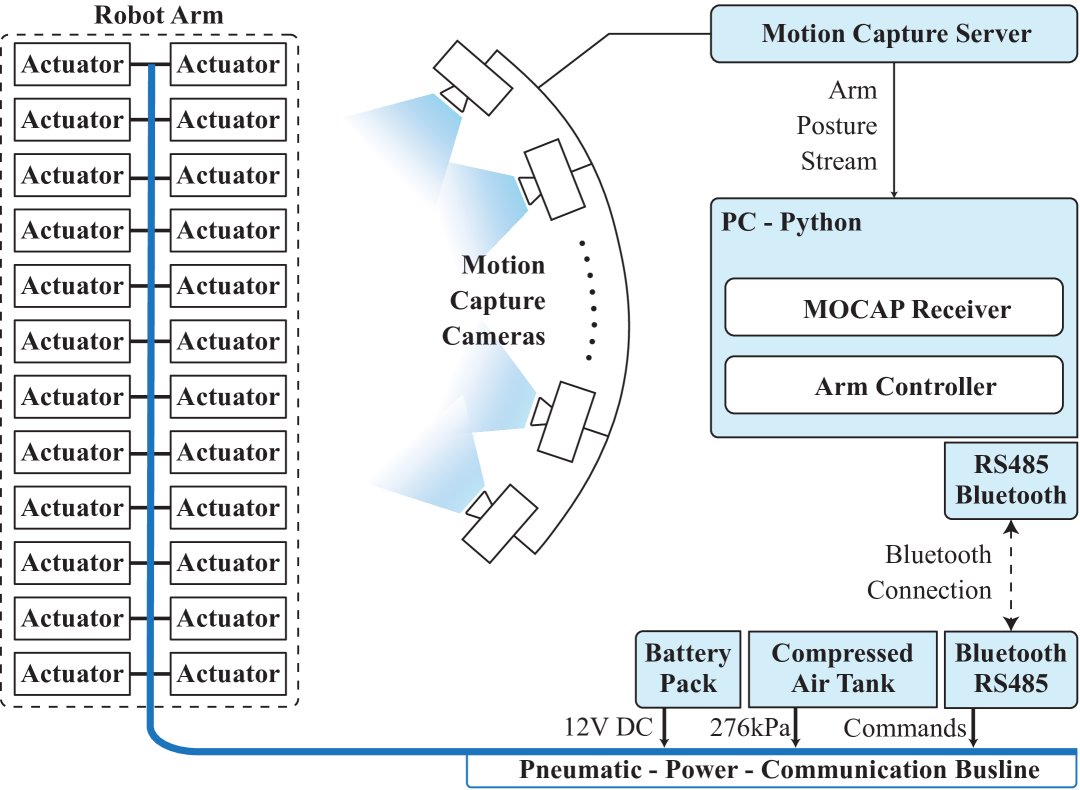
The bulky pressure regulating hardware is distributed into every VEMAs in the arm, therefore, even with a total of 24 independently controlled VEMAs, the UMArm does not need any external regulators. The input to the arm only consists of a single 276kPa(40 psi) pneumatic line and a 4-wire power and communication bus line. This simplicity allows untethered operation. In this work, we use a paintball compressed air tank and a step-down regulator to provide the 276kPa(40 psi) pneumatic pressure, a small Li-ion battery pack to supply 12VDC-2A for the arm’s electronics, and a Bluetooth-RS485 communication module to receive commands from the host PC wirelessly.
III Kinematic Model and Control
III-A Forward Kinematics of the UMArm
The arm is modeled as a 12-revolute joint robot. In this work, we employ the standard product of exponential method [40]. For each U-joint, We define the two revolute joints as illustrated in Fig. 2B. The rotation axes of each of the 12 revolute joints can be expressed as , and we choose as the center of the U-joint, where two revolute axes intersect: . The rotation angle variable for each revolute joint is . The 3 segments of the arm have identical structure, therefore, we can first compute the forward kinematics for each segment consists of 4 joints using , , and :
| (1) |
represents the relative transformation from the base-frame to the tool-frame at robot initial posture, where all . is the twist of a joint, which contains a three-dimensional angular velocity vector and a three-dimensional linear velocity vector. By using the and the joint angle , we can construct the twist exponential . Using the twist exponential for each joint, and the formulation in Equation 1, we can acquire , which is the forward kinematics of one arm segment. It maps from a set of joint angles to the tool frame expressed in the segment base coordinate frame.
We can assemble a full-robot forward kinematics by using the forward kinematics for each segment. The robot’s initial posture () is shown in Fig. 1A: the first segment is mounted on the ceiling and all the links align with the spatial Z-axis. For each segment, the base-frame is the upper link plate in Fig. 2C, and the tool-frame is the lower link plate. The origin of both frames coincides with the center of the U-joints. We assume that the base-frame of the robot is also the base-frame of the first segment. is the link joint offset, i.e., the homogeneous transformation between the current segment tool-frame and the next segment base-frame.
Since the robot consists of three segments, we assume that the tool-frame of the entire robot is the tool-frame of the segment. We can then express the entire robot forward kinematics as:
| (2) |
will yield the tool-frame position and orientation in format expressed in the robot coordinate frame. Robot specific dimensional parameters and more detail regarding the calculation process can be found in the Supplementary Materials. In the actual implementation, we use Wolfram Mathematica to pre-compute one analytic expression of the products of exponential for all three segments. It is a function of segment dimension parameters and segment joint variables. We exported this function to Python for robot control. Kinematic code can be found in the following GitHub repository (link)
III-B Inverse Kinematics of the UMArm
The inverse kinematics of UMArm is achieved through using the iterative inverse Jacobian method [40]. Each revolute joint on the arm has a range of motion. In this work, the inverse kinematics problem will be solved for the position of the end-effector, while we assume that the orientation will be achieved with extra DoFs on the end-effector. “Vanilla” Jacobian inverse kinematics cannot limit the joint angle or smartly distribute motion among the 12 DoF. As a result, the IK solver will output solutions that are not feasible for our physical system. Modifications need to be implemented to the Jacobian IK solver. UMArm has many redundancies granted by the large number of independently actuated muscles. This will make the null space of the manipulator Jacobian non-empty, which effectively means that the robot can change its posture in specific ways while still maintaining the end-effector position. We can use this feature to our advantage to redistribute motion reasonably among the joints. We have implemented a method that combines the gradient projection method [41] and the weighted least norm method [42]. These modifications will encourage each joint to stay within the range of motion limit. The detailed Jacobian derivation and the gradient projection method can be found in Supplementary Materials
III-C Joint Angle Controller
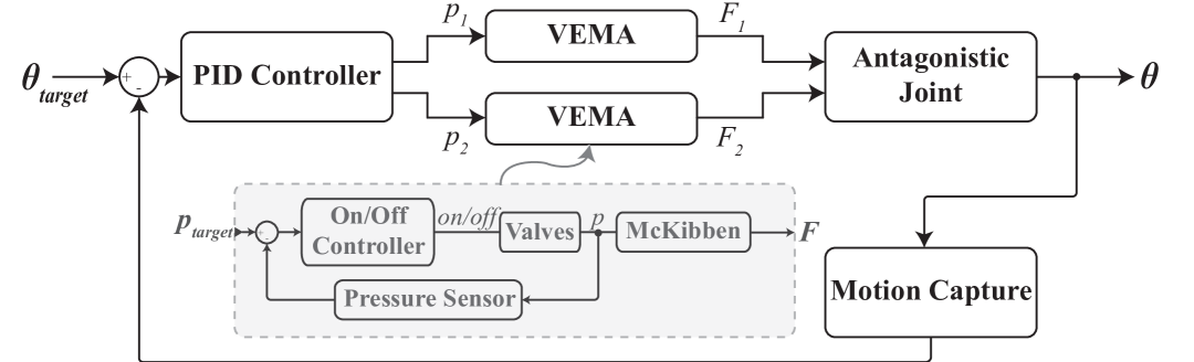
Each revolute joint is designed to be controlled by two VEMAs as described in Fig. 2C. Since the actuators are antagonistically installed, the stiffness of each joint can be tuned by simultaneously actuating the two actuators. The arm user can set the target antagonistic stiffness for each joint as , where will be the minimum pressure for the antagonistic pair of actuators of that joint. We use a standard PID controller for each revolute joint to control the joint angle in a closed-loop manner. As shown in the control diagram in Fig. 3, the PID controller acquires the actual joint angle feedback from the motion capture system. According to the error input, the PID controller will decide the ratio , where and are the pressures in antagonistic VEMAs. Then, depending on the rotation direction, either or will be set to , and the other one will be calculated using .
The antagonistic pressure of all 12 revolute joints can be set independently, which opens up new possibilities for the control of the arm. However, applying antagonistic stiffness to the joint will decrease its range of motion. Therefore, we have a heuristic that will automatically lower the antagonistic pressure when the joint is trying to reach a larger angle. Detailed controller tuning can be found in Supplementary Materials.
IV Characterization of the Arm
IV-A Experiment Setup
In the characterization experiments, the arm’s base is mounted to the ceiling rail, with the arm naturally hanging down as the rest configuration. The arm and its peripheral system are connected as shown in Figure 4. The arm operates using a laboratory compressed air outlet and a 12V DC source. The two-line RS485 serial communication interface connects to an RS485-to-USB adapter, then plugs into the PC. A 12-camera motion capture system is used to track the deformation of the arm. Motion capture markers are installed on cantilever arms on the printed link frame shown in Fig. 2C. Four markers on one link frame define one rigid body. In each rigid body, the four markers form a quadrilateral, and the intersection point of its diagonals aligns with the center of the U-joint. The 3-segment arm has six rigid bodies in total, and the rigid bodies’ positions and orientations can be acquired from the motion capture system. By using the rigid body position and orientation, we can compute each joint angle defined in Figure 2A. A multi-process Python application runs on the laptop PC. One process receives the data stream from the motion capture server, and for each frame, calculates the joint angle of the robot. Another process runs the 12-joint PID controller and the serial interface that sends target pressures to the actuators. A third process is dedicated to the computationally heavy kinematics functions, and the last process runs an interface that receives user commands and visualizes the robot. In the characterization section, a 10 cm rod with 4 motion capture markers (shown in Fig.2A) is installed as the end-effector.
IV-B Step Response of the Arm
The joint angle controller’s performance is characterized by a step response experiment. At , the joint angle controller is enabled, and all 12 joints are set to zero. At , all joints are set to respectively. For better figure readability, we compute the forward kinematics using the target joint angles and the actual joint angles, and plot the end-effector position vs time in figure 5. Another figure with 12 joint angle subplots is available in Supplementary Materials

| Antagonistic/PID | 5% Settling | Tracking RMSE |
|---|---|---|
| High/Aggressive | 1.32s | 0.36° |
| Low/Aggressive | Does not settle | 0.81° |
| Low/Conservative | Oscillate | 1.09° |
To visualize the benefit of having antagonistic stiffening at each joint, we performed the step response experiment with three different stiffnesses and controller tunings. We first used a low antagonistic pressure =14 kPa (2 psi) and fine-tuned the PID gains with our best effort to minimize the tracking error while avoiding excessive oscillation. We define this PID gain profile as “Conservative”, and the tracking result is plotted in Fig. 5 in the medium blue line. The system cannot settle within 5% in the given timeframe, and the average joint angle tracking RMSE for the whole experiment is 1.09°.
Next, we increased the antagonistic pressure of the first(base) segment to 83 kPa (12 psi), the second segment to 8 psi, and the third segment to 28 kPa (4 psi). The antagonistic pressure is in a decreasing order because the segments closer to the base bear a heavier load. Using this stiffness profile, we can significantly increase the PID gains without introducing oscillations. The newly tuned PID gain profile is defined as “Aggressive”, and the tracking result is plotted in a dark blue line. The 5% settling time is 1.32s, and the average joint angle tracking RMSE for the whole experiment is 0.36°, illustrating a significant performance gain by having antagonistic stiffness.
To demonstrate the oscillatory behavior when larger PID gains are applied to a low structural stiffness system, we use the “Aggressive” tuning profile to the low antagonistic setting. The oscillatory behavior is illustrated by the light blue line of Fig. 5.

At “High” antagonistic structural stiffness and “Aggressive” PID tuning, UMArm can achieve a steady-state joint angle RMSE of 0.033 degrees (excluding the error for the first 3s after a new target is given and assuming motion capture data as ground truth for the joint controller).
Qualitatively speaking, a joint with higher antagonistic stiffness will act like a spring with a large spring constant. Upon disturbances, its response will have a lower magnitude. Also, a McKibben actuator at higher pressure can dissipate energy faster due to the larger internal friction between the fibers. Therefore, the joint can structurally (without control) lower the oscillation magnitude and increase the damping factor. As a result, the arm can quickly stabilize when a new joint angle target is given.
IV-C Precision, Payload Capacity, and Untethered Operation
The UMArm’s inverse kinematics controller is characterized by a way-point traversal experiment. The arm is tasked with traversing eight way-points in a specific order, as shown in Figure 7B. Every five seconds, the robot will switch to the next way-point. The inverse kinematics controller is as described in section II. It runs in real time and iteratively updates the target robot configuration. Figure 7A shows the target and the actual position of the end-effector. The inverse kinematics algorithm converges almost instantly, so the tracking error mostly comes from the joint controller. Using the last two seconds from the five-second interval for each way-point, we can compute the average RMSE to be 2.6mm.
Payload capacity is characterized by attaching weights to the tip of the arm and actuating the arm to its maximum bending position. As shown in Figure 8D, we tested payload ranging from 0 to 3 Kg. The range of motion of the arm will be affected by the heavier payload.
The arm can operate untethered using a portable pressure source. We demonstrate this functionality using an off-the-shelf compressed air tank that holds 1.11L (68ci) at 31MPa (4500 psi) (Fig 10A). It was originally built for airsoft players, so it is designed to be portable and lightweight. We characterize the untethered performance by letting the robot traverse the eight way-points in the previous experiment with two 2-second intervals. This experiment shows that the compressed air tank we use could supply the robot to traverse 700 way points, or run continuously for 11min 45s before it starts to lose tracking accuracy due to the depletion of the tank.
V UMArm Demonstrations
V-A Safe and Dexterous Arm
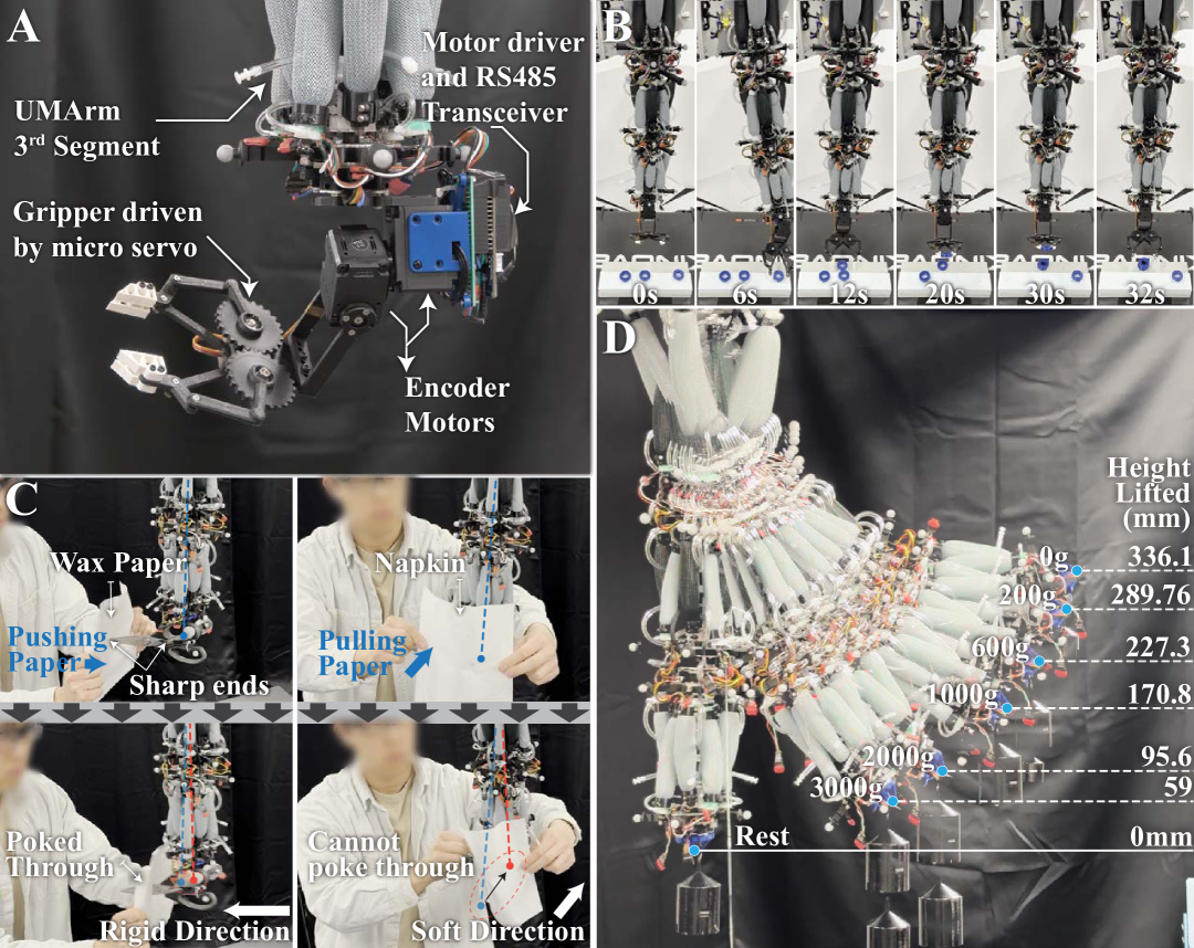
Soft robotic arms are structurally compliant, which is crucial for safe interaction with humans. However, for a robotic arm to be precise and fast, it needs to have control over its structural stiffness. Otherwise, we might see oscillatory behavior or buckling under heavy load. UMArm can control the structural compliance on all 12 joints on the arm. This has granted the UMArm great flexibility to have safety and performance simultaneously. Figure 8C demonstrates UMArm’s directional compliance control capability. Two similarly sharp objects (scissors and a screwdriver) are installed perpendicularly on the end effector. Then, we selectively stiffen some of the joints and relax the other joints to make UMArm structurally stiff along the scissors direction while soft along the screwdriver direction. This directional difference in stiffness can be demonstrated by a human operator holding a piece of paper and pushing it against the two sharp objects. Kitchen wax paper is used on the more rigid direction, while a napkin is used on the soft direction. As shown in Figure 8C, UMArm can poke through the strong wax paper with minimal displacement of the arm, while it cannot poke through a soft napkin along the soft direction.
Having many independently controlled actuators also grants the UMArm the ability to perform delicate tasks. It can move very small distances with great precision. We showcase that ability through an object-stacking experiment. Figure 8A shows the end-effector we have developed for this task. This end-effector consists of two encoder motors, one gripper driven by a servo, and the controller circuits. The two encoder motors can maintain the gripper’s orientation. Figure 8B shows the object stacking experiment. There are three objects on the upper level of a two-level platform. The UMArm picks up and places the first object onto the lower platform, stacks the second object on top of the first object, and stacks the third object on top of both objects. In the supplementary video, the robot can keep repeating this task nonstop with great consistency.
V-B Wearable Assistive Arm
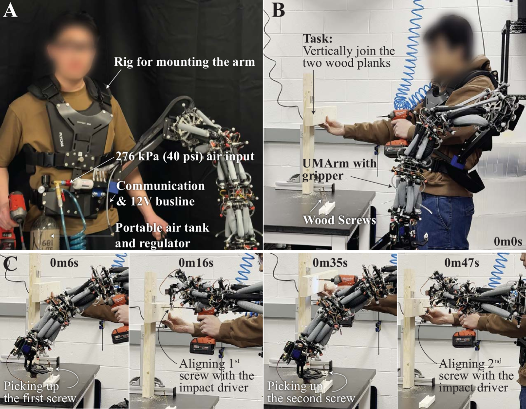
UMArm is very suitable to be a wearable assistive arm because of its lightweight design, untethered operation ability, large payload capacity, and dexterity. Fig. 9A shows a worker wearing the UMArm as a worksite assistive arm. A rig built for a camera stabilizer is repurposed to attach the arm to the worker. The task for the worker is to perpendicularly join two wooden planks using two wood screws. As the worker needs to use one hand to hold the plank and another hand to hold the impact driver, thus an extra hand is needed to hold the wood screw. Figure 9 B&C demonstrates how the UMArm could assist in such a situation. The arm can use the gripper to pick up the first screw from the screw holder, and align the screw at where the worker wants it. As the worker starts to drill in the screw, the arm can automatically pick up the second screw, and align it again. With the help of UMArm, the worker is able to complete the task within one minute.
V-C Inchworm Robot
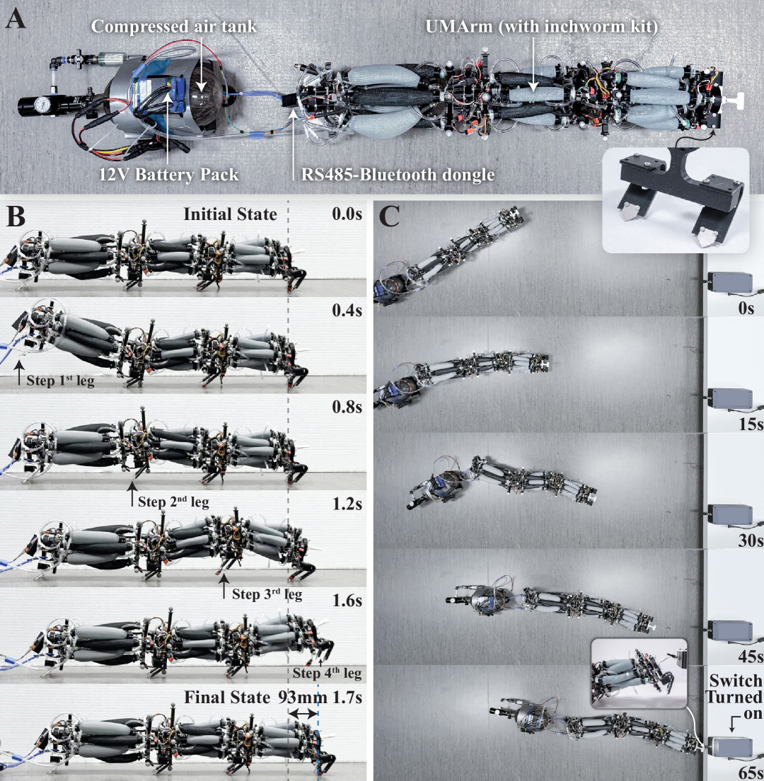
The regulator-embedded design, untethered operation ability, and large number of independently controlled actuators have made the UMArm extremely versatile. We want to demonstrate the versatility by showing that the UMArm can not only serve as a robotic arm, but also operate as a standalone robot that can untetheredly locomote and interact. With some slight modifications, we turned the UMArm into an untethered inchworm robot. Figure 10A shows the modified UMArm. Four legs are installed on the UMArm. The legs are metal spikes that have a 45° angle with the ground. It has less traction sliding forward and larger traction sliding backward. The compressed air tank and 12V battery pack are loaded on a wheeled trailer, which will be tagged along with the inchworm robot. Figure 10B shows the gaits of the inchworm. It raises and steps forward the legs one at a time. When inchworming forward, it can complete one cycle in 1.7 seconds, during which it moves forward by 93 millimeters. A more comprehensive demonstration of its ability is shown in Figure 10C. The inchworm is tasked with turning on the flip switch of a lightbox. It rotates and moves toward the switch. After it aligns its head with the switch, it needs to raise the first segment to flip the switch. However, if the other two segments are relaxed, as the first segment tries to exert force at the switch, the leg between the second and third segments will be lifted up, therefore, not enough force will be exerted onto the switch. Fortunately, the robot can employ the antagonistic stiffening feature to increase the stiffness of the body. By stiffening the body, the two segments at the back will stay straight and provide firm support for the raised first segment, which can now apply enough force to turn on the switch.
VI Discussion
This work demonstrates the hardware novelty of UMArm. We showed that the arm can already accomplish real-world tasks with a basic kinematic model and a PID controller. We anticipate that advanced control techniques tailored to our hardware system could better exploit the UMArm’s capabilities and provide faster and more efficient responses with smartly tuned antagonistic pressure. The arm’s dynamics and advanced controls will be explored in future work. This study also did not fully demonstrate the UMArm’s directional compliance control capabilities. The large number of compliance-controlled DoFs of the arm is designed to quantitatively allow variation in compliance across different directions, enhancing the robot’s ability to safely interact with its environment while retaining necessary support and precision. However, our experiments thus far have only qualitatively demonstrated one compliance profile. Exploring control strategies to realize and fine-tune directional compliance remains an important goal for our next work in progress. Apart from control strategies, several hardware upgrades have been identified to further enhance the UMArm’s performance and robustness. For instance, replacing the present pneumatic valves with higher pressure-rated, high-flow alternatives would enable faster actuation and greater force output. Also, increasing the number of spine segments would expand the arm’s reachable workspace and dexterity.
VII Conclusion
This work introduces the UMArm, a pneumatically actuated rigid-soft hybrid arm that overcomes key limitations in soft robotic arms by integrating 24 independently controlled valve-embedded McKibben actuators. Our design achieves high precision (end-effector steady-state RMSE 2.6 mm), strong force output (3 kg payload), and rapid actuation while remaining lightweight (1.15 kg). Unlike traditional pneumatic arms requiring extensive external hardware, UMArm operates untethered using a compact, onboard pneumatic system, significantly enhancing portability. The modular architecture enables scalability and reconfiguration. The UMArm also demonstrates versatility. It can transform into an untethered inchworm robot that can move and interact. By leveraging antagonistic stiffening, the arm achieves directional compliance control. It can be tuned soft in one direction for safe human interaction, and rigid in the other direction for better force transmission. These advancements position UMArm as a robust solution for precise, wearable, and multimodal robotic applications. In the future, we would like to explore various control strategies that exploit the hardware advantages of the UMArm, striving for the goal of deploying high-performance, structurally compliant arms into the unstructured world.
References
- [1] H. A. Almurib, H. F. Al-Qrimli, and N. Kumar, “A review of application industrial robotic design,” in 2011 Ninth International Conference on ICT and Knowledge Engineering. IEEE, 2012, pp. 105–112.
- [2] T. Brogårdh, “Present and future robot control development—an industrial perspective,” Annual Reviews in Control, vol. 31, no. 1, pp. 69–79, 2007.
- [3] C. C. Kemp, A. Edsinger, and E. Torres-Jara, “Challenges for robot manipulation in human environments [grand challenges of robotics],” IEEE Robotics & Automation Magazine, vol. 14, no. 1, pp. 20–29, 2007.
- [4] G. Zheng, Y. Zhou, and M. Ju, “Robust control of a silicone soft robot using neural networks,” ISA transactions, vol. 100, pp. 38–45, 2020.
- [5] J. Wang and A. Chortos, “Control strategies for soft robot systems,” Advanced Intelligent Systems, vol. 4, no. 5, p. 2100165, 2022.
- [6] M. Yang, E. Yang, R. C. Zante, M. Post, and X. Liu, “Collaborative mobile industrial manipulator: a review of system architecture and applications,” in 2019 25th international conference on automation and computing (ICAC). IEEE, 2019, pp. 1–6.
- [7] C. Zhang, P. Zhu, Y. Lin, Z. Jiao, and J. Zou, “Modular soft robotics: Modular units, connection mechanisms, and applications,” Advanced Intelligent Systems, vol. 2, no. 6, p. 1900166, 2020.
- [8] C. H. Le, D. T. Le, D. Arey, P. Gheorghe, A. M. Chu, X. B. Duong, T. T. Nguyen, T. T. Truong, C. Prakash, S.-T. Zhao et al., “Challenges and conceptual framework to develop heavy-load manipulators for smart factories,” International Journal of Mechatronics and Applied Mechanics, vol. 8, no. 2, pp. 209–216, 2020.
- [9] B. Trimmer, “Soft robots,” Current Biology, vol. 23, no. 15, pp. R639–R641, 2013.
- [10] D. Rus and M. T. Tolley, “Design, fabrication and control of soft robots,” Nature, vol. 521, no. 7553, pp. 467–475, 2015.
- [11] X. Li, Q. Xiong, D. Sui, Q. Zhang, H. Li, Z. Wang, T. Zheng, H. Wang, J. Zhao, and Y. Zhu, “Disturbance-adaptive tapered soft manipulator with precise motion controller for enhanced task performance,” IEEE Transactions on Robotics, 2024.
- [12] Y. Ansari, M. Manti, E. Falotico, Y. Mollard, M. Cianchetti, and C. Laschi, “Towards the development of a soft manipulator as an assistive robot for personal care of elderly people,” International Journal of Advanced Robotic Systems, vol. 14, no. 2, p. 1729881416687132, 2017.
- [13] C. Firth, K. Dunn, M. H. Haeusler, and Y. Sun, “Anthropomorphic soft robotic end-effector for use with collaborative robots in the construction industry,” Automation in Construction, vol. 138, p. 104218, 2022.
- [14] S. K. Mitchell, X. Wang, E. Acome, T. Martin, K. Ly, N. Kellaris, V. G. Venkata, and C. Keplinger, “An easy-to-implement toolkit to create versatile and high-performance hasel actuators for untethered soft robots,” Advanced Science, vol. 6, no. 14, p. 1900178, 2019.
- [15] H. Yang, M. Xu, W. Li, and S. Zhang, “Design and implementation of a soft robotic arm driven by sma coils,” IEEE Transactions on Industrial Electronics, vol. 66, no. 8, pp. 6108–6116, 2018.
- [16] Y. Feng, T. Ide, H. Nabae, G. Endo, R. Sakurai, S. Ohno, and K. Suzumori, “Design of a compliant 7-dof power soft robot driven by hydraulic artificial muscles,” in The 32nd 2021 International Symposium on Micro-NanoMechatronics and Human Science. IEEE, 2021, pp. 1–4.
- [17] Q. Guan, F. Stella, C. Della Santina, J. Leng, and J. Hughes, “Trimmed helicoids: an architectured soft structure yielding soft robots with high precision, large workspace, and compliant interactions,” npj Robotics, vol. 1, no. 1, p. 4, 2023.
- [18] G. M. Whitesides, “Soft robotics,” Angewandte Chemie International Edition, vol. 57, no. 16, pp. 4258–4273, 2018.
- [19] M. S. Xavier, C. D. Tawk, A. Zolfagharian, J. Pinskier, D. Howard, T. Young, J. Lai, S. M. Harrison, Y. K. Yong, M. Bodaghi et al., “Soft pneumatic actuators: A review of design, fabrication, modeling, sensing, control and applications,” IEEE Access, vol. 10, pp. 59 442–59 485, 2022.
- [20] J. F. García-Samartín, A. Rieker, and A. Barrientos, “Design, manufacturing, and open-loop control of a soft pneumatic arm,” in Actuators, vol. 13, no. 1. MDPI, 2024, p. 36.
- [21] K. C. Galloway, K. P. Becker, B. Phillips, J. Kirby, S. Licht, D. Tchernov, R. J. Wood, and D. F. Gruber, “Soft robotic grippers for biological sampling on deep reefs,” Soft robotics, vol. 3, no. 1, pp. 23–33, 2016.
- [22] D. Trivedi, C. D. Rahn, W. M. Kier, and I. D. Walker, “Soft robotics: Biological inspiration, state of the art, and future research,” Applied bionics and biomechanics, vol. 5, no. 3, pp. 99–117, 2008.
- [23] I. A. Seleem, H. El-Hussieny, and H. Ishii, “Recent developments of actuation mechanisms for continuum robots: A review,” International Journal of Control, Automation and Systems, vol. 21, no. 5, pp. 1592–1609, 2023.
- [24] O. Sokolov, A. Hošovskỳ, and M. Trojanová, “Design, modelling, and control of continuum arms with pneumatic artificial muscles: A review,” Machines, vol. 11, no. 10, p. 936, 2023.
- [25] R. Zuo, M. Mehta, D. H. Han, and D. Bruder, “Embedded valves for distributed control of soft pneumatic actuators,” in 2024 IEEE/RSJ International Conference on Intelligent Robots and Systems (IROS). IEEE, 2024, pp. 8286–8292.
- [26] D. Bruder, X. Fu, R. B. Gillespie, C. D. Remy, and R. Vasudevan, “Data-driven control of soft robots using koopman operator theory,” IEEE Transactions on Robotics, vol. 37, no. 3, pp. 948–961, 2020.
- [27] D. Li, V. Dornadula, K. Lin, and M. Wehner, “Position control for soft actuators, next steps toward inherently safe interaction,” Electronics, vol. 10, no. 9, p. 1116, 2021.
- [28] L. Hongwei, X. Yan, Y. Huxiao et al., “Kinematic modeling and control of a novel pneumatic soft robotic arm,” Chinese Journal of Aeronautics, vol. 35, no. 7, pp. 310–319, 2022.
- [29] C. Alessi, E. Falotico, and A. Lucantonio, “Ablation study of a dynamic model for a 3d-printed pneumatic soft robotic arm,” IEEE Access, vol. 11, pp. 37 840–37 853, 2023.
- [30] Y. Zhu, T. Wang, W. Gong, K. Feng, X. Wang, and S. Xi, “Design and motion analysis of soft robotic arm with pneumatic-network structure,” Smart Materials and Structures, vol. 33, no. 9, p. 095038, 2024.
- [31] H. Jiang, Z. Wang, Y. Jin, X. Chen, P. Li, Y. Gan, S. Lin, and X. Chen, “Design, control, and applications of a soft robotic arm,” arXiv preprint arXiv:2007.04047, 2020.
- [32] W. McMahan, V. Chitrakaran, M. Csencsits, D. Dawson, I. Walker, B. Jones, M. Pritts, D. Dienno, M. Grissom, and C. Rahn, “Field trials and testing of the octarm continuum manipulator,” in Proceedings 2006 IEEE International Conference on Robotics and Automation, 2006. ICRA 2006., 2006, pp. 2336–2341.
- [33] P. Ohta, L. Valle, J. King, K. Low, J. Yi, C. G. Atkeson, and Y.-L. Park, “Design of a lightweight soft robotic arm using pneumatic artificial muscles and inflatable sleeves,” Soft robotics, vol. 5, no. 2, pp. 204–215, 2018.
- [34] D. Bruder, M. A. Graule, C. B. Teeple, and R. J. Wood, “Increasing the payload capacity of soft robot arms by localized stiffening,” Science Robotics, vol. 8, no. 81, p. eadf9001, 2023.
- [35] Y. Liu, W. Shi, P. Chen, Y. Yu, D. Zhang, and D. Wang, “Design and experiment of a novel pneumatic soft arm based on a deployable origami exoskeleton,” Frontiers of mechanical engineering, vol. 18, no. 4, p. 54, 2023.
- [36] N. Oh, H. Lee, J. Shin, Y. Choi, K.-J. Cho, and H. Rodrigue, “Hybrid hard-soft robotic joint and robotic arm based on pneumatic origami chambers,” IEEE/ASME Transactions on Mechatronics, 2024.
- [37] X. Zhou, C. Wu, S. Cai, and G. Bao, “A pneumatic-actuated flexible robotic arm with rigid backbone for high-precision and safe manipulation,” IEEE/ASME Transactions on Mechatronics, 2024.
- [38] D. Bruder and R. J. Wood, “The chain-link actuator: Exploiting the bending stiffness of mckibben artificial muscles to achieve larger contraction ratios,” IEEE Robotics and Automation Letters, vol. 7, no. 1, pp. 542–548, 2021.
- [39] D. Bruder, A. Sedal, R. Vasudevan, and C. D. Remy, “Force generation by parallel combinations of fiber-reinforced fluid-driven actuators,” IEEE Robotics and Automation Letters, vol. 3, no. 4, pp. 3999–4006, 2018.
- [40] R. M. Murray, Z. Li, and S. S. Sastry, A mathematical introduction to robotic manipulation. CRC press, 2017.
- [41] A. Liegeois et al., “Automatic supervisory control of the configuration and behavior of multibody mechanisms,” IEEE transactions on systems, man, and cybernetics, vol. 7, no. 12, pp. 868–871, 1977.
- [42] T. F. Chan and R. V. Dubey, “A weighted least-norm solution based scheme for avoiding joint limits for redundant joint manipulators,” IEEE transactions on Robotics and Automation, vol. 11, no. 2, pp. 286–292, 1995.