Index Modulated Affine Frequency Division Multiplexing With Spread Spectrum
Abstract
The recently proposed affine frequency division multiplexing (AFDM) is a new transmission waveform that has shown excellent performance in high-mobility environments, making it a sensible option for the next-generation wireless networks. In this paper, we investigate an energy-efficient index modulation scheme for AFDM by leveraging spread spectrum, referred to as IM-AFDM-SS, to combat the interference caused by the doubly dispersive channels. Specifically, the information bits are conveyed by the transmitted symbols as well as the indices of the selected spreading codes in our proposed IM-AFDM-SS scheme. To avoid extensive computations, we also develop a low-complexity maximal ratio combining (MRC) detector algorithm, which recovers the spreading codes first and demodulates the symbols afterwards. Moreover, an upper bound on the bit error rate (BER) of the proposed IM-AFDM-SS system with maximum-likelihood (ML) detection is derived. Numerical results demonstrate the superiority of the proposed IM-AFDM-SS system over the classical AFDM spread spectrum (AFDM-SS) and the existing index modulated AFDM (IM-AFDM) systems.
Index Terms:
AFDM modulation, index modulation, spread spectrum, doubly selective fading channels.I Introduction
The sixth-generation (6G) wireless networks are expected to achieve ultra-reliable, high energy-efficient, and wide coverage communications in high mobility wireless communications, such as high-speed railway and vehicle-to-everything communications [1, 2, 3]. In these scenarios, wireless channels can be characterized by large delay and Doppler spreads, which poses a huge challenge for reliable communications. The widely developed orthogonal frequency division multiplexing (OFDM) systems may not be an optimal solution because of the terrible performance degradation caused by the inter-carrier-interference (ICI) [4]. Therefore, developing a new modulation waveform to cope with various challenges in high-mobility communication scenarios is essential.
Against this background, a promising chirp-based multicarrier waveform, named affine frequency division multiplexing (AFDM) was proposed in [5, 6] with high robustness to Doppler spread. The key idea of AFDM is to multiplex the information symbols into a set of orthogonal chirps via inverse discrete affine Fourier transform (IDAFT). By tuning the chirp rate to accommodate the maximum delay spread and maximum Doppler shifts, AFDM can separate all channel paths, ensuring that each symbol experiences multipath fading. Therefore, AFDM can exploit the full diversity in the doubly dispersive channels, achieving performance comparable to that of orthogonal time-frequency space (OTFS) [7, 8, 9] and superior to that of traditional OFDM. Furthermore, AFDM enjoys lower implementation complexity and pilot overhead than OTFS since the two-dimensional delay-Doppler domain in OTFS is transformed into a one-dimensional discrete affine Fourier transform (DAFT) domain, leading to a lower guard pilots [10, 11, 12].
Recently, a novel multicarrier transmission technique known as index modulated AFDM, termed as IM-AFDM, has been introduced to enhance the bit error rate (BER) performance over high-mobility communications [13]. In IM-AFDM, index modulation (IM) operates the transmission of information through the indices of the building blocks of the communication system, such as antennas, subcarriers, and time slots [14]. By embedding these indices into the transmitted signal, the IM-AFDM scheme significantly enhances both spectral and energy efficiency. Moreover, the IM-AFDM scheme can achieve better BER performance than classical AFDM at the same spectral efficiency (SE). Due to the advantages of IM, several studies have focused on combining AFDM with subcarrier IM, yielding promising results. However, in conventional IM-AFDM schemes, although there is no symbol transmission for the inactive chirp subcarriers, it still experiences severe inter-carrier interference since the fractional Doppler spreads across the entire DAFT domain. To the best of our knowledge, the existing IM-AFDM works have neglected this pivotal problem and exhibit performance loss.
To alleviate the ICI in doubly dispersive channels, a novel index modulation scheme based on AFDM spread spectrum (AFDM-SS), termed as IM-AFDM-SS, is proposed in this paper. This innovative study is the first of its kind to exploit the potential of spread spectrum (SS) with IM-AFDM to overcome the Doppler spread in the doubly selective fading channels. The main idea is to select an orthogonal code to spread an -ary constellation symbol over the chirp subcarriers, utilizing the indices of spreading code to convey extra information bits. The contributions of this paper can be summarized as follows: 1) We propose a novel IM-AFDM-SS scheme to effectively overcome the ICI caused by high Doppler spread, ensuring superior BER performance. 2) We also develop a low-complexity maximal ratio combining (MRC) detection algorithm for IM-AFDM-SS, which exhibits robustness against the imperfect channel state information (CSI). 3) Numerical results demonstrate that the derived BER upper bound curves match closely with the simulation results, and the proposed IM-AFDM-SS scheme significantly outperforms the benchmark schemes in high-mobility channels.
II System Model
II-A Transmitter
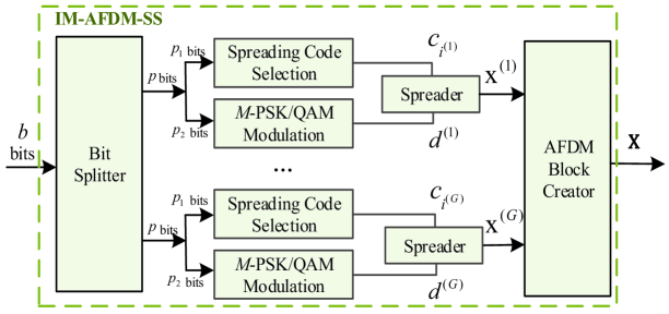
Let denote the sample period, and denote the the number of subcarriers (chirps). The IM-AFDM-SS symbols are transmitted with a bandwidth , and subcarrier spacing . For each AFDM block, a total of information bits are transmitted. As shown in Fig. 1, the bits are separated into subblocks, where each subblock containing bits. Since the IM mapping operation within subcarriers in each subblock is the same and independent, let us take the -th subblock as an example, where . The transmitted bits of our proposed IM-AFDM-SS system are carried by the index of the selected spreading code as well as the -ary modulated symbols. In the -th subblock, the incoming bits are first divided into two parts such that , where for selecting a Walsh-Hadamard spreading code, and for choosing an -ary constellation symbol, respectively. The first part of bits are applied to the index mapper to determine the activated spreading codes from a predefined set , where denotes the index of the spreading code for the -th subblock. The second part are applied to the modulation symbol index mapper to determine the activated symbols , where with is the -ary phase shift keying (PSK) or quadrature amplitude modulation (QAM) constellation set. The SE of the proposed IM-AFDM-SS system is calculated as .
During the IM-AFDM-SS process, the transmitted symbol of the -th subblock is spreaded across subcarriers by the selected spreading code , yielding
| (1) |
where , denotes the -th element of .
After obtaining the index information and the constellation symbol of all the IM-AFDM-SS subblocks, the AFDM block creator generates a discrete affine Fourier domain symbol as
| (2) |
The corresponding AFDM time domain signal is given by inverse discrete affine Fourier transform (IDAFT) on x, i.e.,
| (3) |
where the adjustable DAFT parameters and are optimized to prevent different channel delay and Doppler overlapping. The equation (3) can be written in a matrix form as
| (4) |
where denotes the DAFT matrix, F represents the discrete Fourier transform (DFT) matrix with entries and .
Before transmitting the time-domain signal , a prefix is required to combat multipath propagation and makes the channel lie in a periodic domain. Unlike OFDM, AFDM employs a chirp-periodic prefix (CPP) here instead of a cyclic prefix (CP) due to the inherent periodicity of DAFT. We assume that the length of CPP is greater than the maximum path delay spread, to avoid the inter-block interference.
II-B Channel Model
Consider a linear time-varying (LTV) channel between the transmitter and receiver with resolvable propagation paths, which can be modeled as
| (5) |
where denotes the unit pulse function. The complex channel gain of the -th path follows a distribution of . Each path includes a unique delay shift and Doppler shift , where and denote the maximum delay shift and maximum Doppler shift, respectively. Here, is the Doppler shift normalized with respect to the subcarrier spacing, where and denote the integer and fractional components of , respectively. Note that our channel model is general and each delay tap can be equipped with different Doppler shifts, i.e., , and .
II-C Receiver
After transmission over the doubly-selective channel, the received time domain signal can be written as
| (6) |
where represents the complex additive white Gaussian noise (AWGN).
After discarding the CPP, (6) can be rewritten in a matrix form as follows
| (7) |
where is the time domain noise vector. denotes the effective time domain channel matrix, whose -th path is fully composed of four parameters: a) a complex channel fading coefficient , b) a diagonal matrix related to CPP , c) a Doppler shift matrix , and d) a forward cyclic-shift matrix .
Finally, after performing the -point DAFT on the received signal r, one can obtain the output symbols in the DAF-domain as given by
| (8) |
The matrix representation of the input-output relationship in the DAFT domain can be written as
| y | ||||
| (9) |
where is the -th path subchannel matrix in the DAFT domain, denotes the effective channel matrix, and represents the effective noise vector that has the same statistical properties as w.
Upon receiving the DAFT domain signal y, we introduce two detection methods for the proposed IM-AFDM-SS scheme, including the ML detector and low-complexity MRC detector.
1) ML detector: At the receiver, we need to detect the indices of the active spreading code and the corresponding data symbols. From (9), the ML detector makes a joint decision by searching all possible index combinations and signal constellation points, which is given by
| (10) |
where i and d denote the indices of the selected spreading code and the transmitted -ary modulation symbols, respectively. Here, we denote with , , and let represents an -PSK/QAM symbol. The corresponding transmitted bits can be recovered from and . Since and possess and possibilities in each subblock, the computational complexity of the ML detector is easy to be calculated by . Obviously, the decoding complexity increases exponentially as the increase of , which limits the application of ML to the large values of . To avoid this computation burden, we propose a novel low-complexity detector as below.
2) Low-complexity MRC detector: In this detector, the first step is to estimate the activated spreading code, followed by detecting the constellation symbol using the estimated spread code obtained in the first step.
At the receiver, the signal y is first fed into an equalizer. After equalization, the signal is divided into groups, with each group undergoing multiplication by the Walsh matrix. According to the MRC detector, the output of -th group is give by , where denotes -th elements of the equalized signal . To effectively identify the indices of the selected spreading code in each group, we compare the squared outputs of branches in each group via
| (11) |
According to the obtained , we can estimate the constellation symbols by searching all possible signal constellation points, as given by
| (12) |
Based on the above analysis, it is obvious that the computation complexity of the proposed IM-AFDM-SS detector is of order , which is lower than that of the ML algorithm. Therefore, the proposed low-complexity MRC detector is particularly suitable for high-dimensional detection.
III Performance Analysis
In this section, we derive an upper bound of the average BER of our proposed IM-AFDM-SS system under Rayleigh fading channels.
Based on the transmission model (9), we can represent the DAFT domain signal as
| (13) |
where channel gain is given by , and is the concatenated matrix constructed as follows
| (14) |
The elements of x is normalized so that the average energy of x is unit. Assume the perfect channel state information is known at the receiver. The erroneously decoded symbols can be caused by either indices of active spreading code or constellation symbols when x is transmitted, where . From (13) and (14), the conditional pairwise error probability (PEP) between two distinct data x and of the proposed IM-AFDM-SS can be calculated as
| (15) |
where and . Here, represents the tail distribution function of a standard normal distribution. By applying the approximation into (15), we can derive an approximate unconditional PEP as
| (16) |
where and . Since the matrix is a Hermitian matrix, we define its rank and the distinct non-zero eigenvalues as and , , respectively. As a results, it follows that
| (17) |
where U denotes a unitary matrix, the diagonal matrix . In (17), represents the -th element of the vector , which is obtained by multiplying h with a unitary matrix. Thus, has the same distribution as h.
Assuming each path has independent Rayleigh distribution, the unconditional PEP in (16) can be approximated as
| (18) |
At high SNRs, i.e., , (18) can be further approximated to
| (19) |
According to the union bounding technique, we can derive the average bit error probability (ABEP) upper bound of the proposed IM-AFDM-SS system as
| (20) |
where denotes the Hamming distance for an arbitrary pair of with .
IV Numerical Results
In this section, we present the BER performance of the proposed IM-AFDM-SS system with chirp subcarrier spacing of 15 kHZ and carrier frequency of 4 GHz. Besides, we consider and is set as an arbitrary irrational number. Each path is assumed to be independent and the channel gains of all paths follow the distribution of . Unless otherwise stated, the fractional Doppler case is employed, and the factional Doppler shift of each path is generated by Jake’s formula [5]. Notably, “IM-AFDM ” is referred to as the IM-AFDM scheme in which out of chirp subcarriers are active. For comparison, we set the classical AFDM [5], IM-AFDM [13] and AFDM-SS schemes as the benchmarks.
Fig. 2 illustrates the analytical and simulated BER performance of the ML detector for the proposed IM-AFDM-SS scheme, where and QPSK are employed. One can observe that all the simulated curves closely match with the analytical BERs in the high SNR region, which confirms the effectiveness of our PEP theoretical analysis. A discrepancy between the analytical and simulated BER is observed at low SNRs as the approximation in (20) is more precise at high SNRs. Moreover, the proposed IM-AFDM-SS scheme enjoys superior performance improvement as the number of channel paths increases from to . This is due to the fact that a larger diversity gain can be exploited as the number of independent resolvable paths increases.
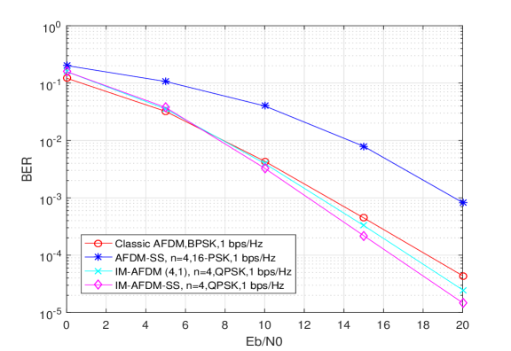
In Fig. 3, we compare the BER performance of IM-AFDM-SS with and QPSK, classical AFDM with and BPSK, AFDM-SS with and 16-PSK, and IM-AFDM with , and QPSK at the same SE of 1bps/Hz. One can notice that the proposed IM-AFDM-SS scheme outperforms both the classical AFDM, AFDM-SS and IM-AFDM schemes in the medium-to-high SNR regime. Approximately 1dB gain can be achieved at a BER level of by IM-AFDM-SS scheme compared with the conventional IM-AFDM scheme. The performance gain of our IM-AFDM-SS scheme can be interpreted by the fact that the spreading code achieves superior inter-carrier interference mitigation compared to partial subcarrier data transmission. The AFDM-SS system demonstrates limited performance as higher-order modulation results in severe performance deterioration.
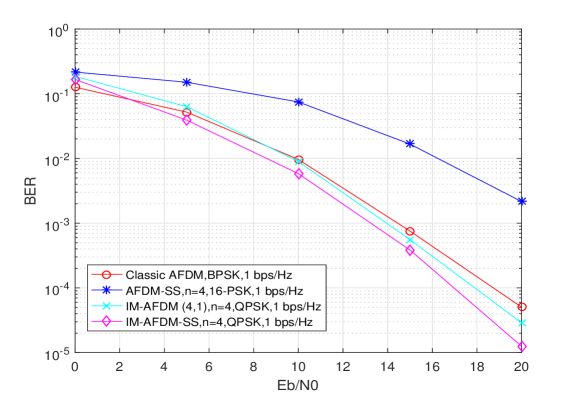
Fig. 4 compares the BER performance of the IM-AFDM-SS scheme with and QPSK, and that of the classical AFDM with and BPSK, AFDM-SS with and 16-PSK, and IM-AFDM with , and QPSK by using the proposed low-complexity MRC detector. Similar to the observations in Fig. 3, the proposed IM-AFDM-SS scheme achieves a higher performance gain than the conventional benchmark schemes. This results powerfully identify the superiority and dependability of our proposed IM-AFDM-SS scheme and MRC detector in terms of high-dimensional transmissions.
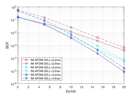
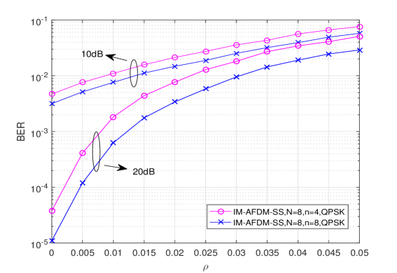
In Fig. 5, the performance of our proposed IM-AFDM-SS scheme with different lengths of spreading code is tested for imperfect CSI. As shown in Fig. 5, our analysis indicates that the performance loss of the proposed IM-AFDM-SS scheme remains mild even under moderate values of channel uncertainty . The acceptable degradation of BER performance demonstrates the robustness of our proposed IM-AFDM-SS scheme against channel modeling errors. Moreover, a higher coding gain can be obtained by increasing the lengths of spreading code. The proposed IM-AFDM-SS scheme provides a flexible trade-off between the SE and BER performance by modifying .
V Conclusion
In this paper, we proposed an innovative IM-AFDM structure with spread spectrum, termed as IM-AFDM-SS, to overcome the inter-carrier interference of the doubly dispersive channels. The theoretical BER upper bounds for the proposed IM-AFDM-SS scheme was derived and validated by the Monte Carlo simulations. The performance comparison results of both the ML and low-complexity MRC detectors indicated that the proposed IM-AFDM-SS scheme outperforms the benchmark schemes. Thanks to the abovementioned superiority, the proposed IM-AFDM-SS would be a promising and viable transmission scheme for practical high-mobility communications. In the future, we will explore our proposed scheme with multiple access and multiple-input-multiple-output (MIMO) systems.
References
- [1] M. Noor-A-Rahim, Z. Liu, H. Lee, M. O. Khyam, J. He, D. Pesch, K. Moessner, W. Saad, and H. V. Poor, “6G for vehicle-to-everything (V2X) communications: Enabling technologies, challenges, and opportunities,” Proc. IEEE, vol. 110, no. 6, pp. 712–734, Jun. 2022.
- [2] L. Xiao, S. Li, Y. Qian, D. Chen, and T. Jiang, “An overview of OTFS for internet of things: Concepts, benefits, and challenges,” IEEE Internet Things J., vol. 9, no. 10, pp. 7596–7618, May 2022.
- [3] C. D. Alwis et al., “Survey on 6G frontiers: Trends, applications, requirements, technologies and future research,” IEEE Open J. Commun. Soc., vol. 2, pp. 836–886, Apr. 2021.
- [4] M. Wen, J. Li, S. Dang, Q. Li, S. Mumtaz, and H. Arslan, “Joint-mapping orthogonal frequency division multiplexing with subcarrier number modulation,” IEEE Trans. Commun., vol. 69, no. 7, pp. 4306–4318, Jul. 2021.
- [5] A. Bemani, N. Ksairi, and M. Kountouris, “Affine frequency division multiplexing for next generation wireless communications,” IEEE Trans. Wireless Commun., vol. 22, no. 11, pp. 8214–8229, Nov. 2023.
- [6] Y. Tao, M. Wen, Y. Ge, J. Li, E. Basar, and N. Al-Dhahir, “Affine frequency division multiplexing with index modulation: Full diversity condition, performance analysis, and low-complexity detection,” IEEE J. Sel. Areas Commun., vol. 43, no. 4, pp. 1041–1055, Apr. 2025.
- [7] Q. Deng, Y. Ge, and Z. Ding, “A unifying view of OTFS and its many variants,” IEEE Commun. Surv. Tuts., pp. 1–1, 2025. [Online]. Available: https://ieeexplore.ieee.org/stamp/stamp.jsp?arnumber=10891132
- [8] S. Li, J. Yuan, W. Yuan, Z. Wei, B. Bai, and D. W. K. Ng, “Performance analysis of coded OTFS systems over high-mobility channels,” IEEE Trans. Wireless Commun., vol. 20, no. 9, pp. 6033–6048, Sep. 2021.
- [9] M. Qian, F. Ji, Y. Ge, M. Wen, X. Cheng, and H. V. Poor, “Block-wise index modulation and receiver design for high-mobility OTFS communications,” IEEE Trans. Commun., vol. 71, no. 10, pp. 5726–5739, Oct. 2023.
- [10] Q. Luo, P. Xiao, Z. Liu, Z. Wan, N. Thomos, Z. Gao, and Z. He, “AFDM-SCMA: A promising waveform for massive connectivity over high mobility channels,” IEEE Trans. Wireless Commun., vol. 23, no. 10, pp. 14 421–14 436, Oct. 2024.
- [11] H. Yin, X. Wei, Y. Tang, and K. Yang, “Diagonally reconstructed channel estimation for MIMO-AFDM with inter-doppler interference in doubly selective channels,” IEEE Trans. Wireless Commun., vol. 23, no. 10, pp. 14 066–14 079, Oct. 2024.
- [12] H. Yuan, Y. Xu, X. Guo, Y. Ge, T. Ma, H. Li, D. He, and W. Zhang, “PAPR reduction with pre-chirp selection for affine frequency division multiplexing,” IEEE Wireless Commun. Lett., vol. 14, no. 3, pp. 736–740, Mar. 2025.
- [13] J. Zhu, Q. Luo, G. Chen, P. Xiao, and L. Xiao, “Design and performance analysis of index modulation empowered AFDM system,” IEEE Wireless Commun. Let., vol. 13, no. 3, pp. 686–690, Mar. 2024.
- [14] T. Mao, Q. Wang, Z. Wang, and S. Chen, “Novel index modulation techniques: A survey,” IEEE Commun. Surv. Tut., vol. 21, no. 1, pp. 315–348, 2019.