Max–Min Fairness in Stacked Intelligent Metasurface-Aided Rate Splitting Networks
Abdullah Quran, Shimaa Naser, Maryam Tariq, Omar Alhussein, and Sami Muhaidat
Abstract
This paper investigates a downlink multiuser multiple-input single-output system that integrates rate-splitting multiple access (RSMA) with a stacked intelligent metasurface (SIM) to enable wave-domain beamforming. Unlike conventional digital beamforming, the proposed system leverages the programmable phase shifts of the SIM to perform beamforming entirely in the wave domain. In contrast to existing literature, this work introduces a fairness-centric SIM-RSMA design that shifts the emphasis from maximizing sum-rate to ensuring fair allocation of resources. In particular, we formulate a max–min rate optimization problem that jointly optimizes transmit power coefficients at the base station and SIM phase shifts. Given the non-convex nature of this problem, we develop an alternating optimization framework, where the power allocation is optimized through successive convex approximation and SIM beamforming is optimized using the Riemannian conjugate gradient method. Simulation results indicate that combining SIM with RSMA yields superior max–min performance compared to its integration with space division multiple access or non-orthogonal multiple access.
Index Terms:
Rate-splitting multiple access (RSMA), stacked intelligent metasurface (SIM), wave-domain beamforming.I Introduction
With the increasing demand for higher data rates and more energy-efficient infrastructure, traditional beamforming techniques that rely heavily on digital signal processing and radio frequency (RF) chains become increasingly complex, and costly, particularly for multi-user environments. In this regard, reconfigurable intelligent surfaces (RISs) have emerged as a transformative technology, enabling programmable control over electromagnetic (EM) wave propagation via passive meta-atom arrays [1]. These surfaces enhance spectral efficiency and energy efficiency by imposing tunable phase shifts on incident waves [2, 3]. However, conventional RISs are typically limited to single-layer reflection, acting as passive relays with limited spatial processing capabilities, which constrains their performance in complex wireless environments. To address these challenges, stacked intelligent metasurfaces (SIMs), inspired by multi-layer diffractive optics [4], have been recently proposed to enable complex beamforming operations in the wave domains using multiple stacked metasurface layers, which reduces the reliance on digital beamforming hardware [5, 6]. Recent works have demonstrated the potential of SIMs in multiuser wave-domain beamforming [7, 8], and integrated sensing and communication [9].
Likewise, rate-splitting multiple access (RSMA) has emerged as a powerful and flexible strategy for multiuser interference management. By splitting each message into a common part decoded by all users and private parts decoded individually, RSMA enables partial interference decoding yielding superior spectral efficiency compared to conventional schemes such as space-division multiple access (SDMA) and non-orthogonal multiple access (NOMA) [10, 11, 12].
Recent studies have explored the integration of RSMA with RISs to enhance spectral efficiency and interference management [13]. However, their performance is constrained by the limited beamforming resolution of single-layer RIS. In contrast, SIM enables high-precision beamforming, suppressing inter-user interference via focused beam alignment. This fine-grained spatial control complements the interference management strategy of RSMA, which mitigates residual interference through message splitting. When combined, SIM and RSMA form a robust and synergistic framework for improving multiuser performance in interference-limited and dense wireless environments. Furthermore, SIM’s analog architecture reduces energy consumption and hardware complexity by eliminating the need for a digital beamformer. Despite these advantages, the integration of SIM and RSMA remains unexplored, particularly in fairness-centric designs such as max–min rate optimization.
Existing SIM literature primarily focuses on single-user systems [5] or conventional multiple access schemes [8]. While RSMA has been considered in metasurface-assisted systems where dual-polarized SIMs are used to enhance digital beamforming [14], this hybrid analog–digital architecture differs from the fully wave-domain beamforming approach adopted in this work. At the time of submission, the authors became aware of an early-access paper [15], which is the only existing work that explores SIM-RSMA systems and focuses on sum-rate maximization. However, it does not address fairness, a major challenge in multiuser systems where a desired quality of service must be ensured for all users. To bridge this gap, we propose a fairness-centric SIM-assisted RSMA framework for downlink multiuser MISO systems, wherein SIM performs all beamforming operations entirely in the wave domain. This design eliminates the need for digital precoding hardware while enabling efficient and equitable user performance. The main contributions of this work are summarized as follows:
-
•
We propose a SIM-RSMA scheme where wave-domain beamforming via the SIM synergizes with RSMA’s message splitting to maximize the minimum user rate. To this end, a max–min rate optimization problem is formulated to jointly optimize the transmit power and SIM phase shifts. However, solving the formulated problem is inherently difficult due to strong coupling between power allocation variables and SIM phase shifts within the non-convex objective function and constraints, making conventional optimization approaches inadequate.
-
•
To address the non-convexity arising from the coupling between power allocation and SIM phase shifts, an alternating optimization (AO) framework is proposed. Transmit power is updated using successive convex approximation (SCA), while SIM beamforming is refined using the Riemannian conjugate gradient (RCG) method.
-
•
The proposed SIM-RSMA scheme performance is evaluated against SIM-SDMA and SIM-NOMA baselines. Results show that SIM-RSMA achieves a higher minimum user rate, demonstrating the effectiveness of combining wavedomain beamforming with RSMA’s interference management. Moreover, the use of multilayer SIM is shown to achieve better fairness performance compared to conventional single-layer RIS structures
II System Model and Problem Formulation
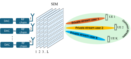
As illustrated in Fig. 1, we consider a downlink multiuser MISO system where a base station (BS) equipped with antennas communicates with single-antenna user equipments (UEs) via 1-layer RSMA [11]. In this work, we propose a SIM-based architecture. The SIM consists of programmable metasurface layers with meta-atoms per layer, to perform beamforming directly in the EM domain. The transmitted signal consists of a common stream decodable by all UEs and private streams intended for individual UEs. Let , , and represent the sets of metasurfaces, meta-atoms per layer, and UEs, respectively. The phase shift matrix corresponding to the -th metasurface layer is denoted as , , where represents the EM response of the -th meta-atom on the -th metasurface layer, and denotes the corresponding phase shift.
The Rayleigh–Sommerfeld diffraction theory is employed to characterize the EM coupling between adjacent metasurface layers. Specifically, the propagation between the -th and -th metasurface layers is described by a transmission matrix , defined for all , . The -th entry, , of denotes the transmission coefficient from the -th meta-atom on the -th layer to the -th meta-atom on the -th layer, and is given by
| (1) |
where is the wavelength, is the area of each meta-atom, denotes the angle between the propagation direction and the surface normal, and is the corresponding propagation distance. The BS-to-SIM transformation matrix is denoted by , where each models the response from the -th transmit antenna to the first metasurface layer. Following the convention in [9, 7, 8, 15], we assume each antenna is associated with one user. To support RSMA with private streams and one common stream, we set , where the first antennas correspond to the private messages and the -th antenna to the common message. The complete wave-domain response of the SIM is expressed as
| (2) |
To model the end-to-end downlink channel from the SIM to each user, we assume a quasi-static flat-fading scenario. Let denote the effective channel vector from the SIM to the -th user. The channel is assumed to follow a correlated Rayleigh fading model given by , where represents the distance-dependent path loss, and is the spatial correlation matrix characterizing coupling between the meta-atoms. Under an isotropic multipath environment with a uniform power azimuth spectrum, the correlation between the -th and -th meta-atoms is modeled as , where is the spacing between meta-atoms, is the carrier wavelength, and is the normalized sinc function [16].
Using the 1-layer RSMA strategy [11], the BS transmits a signal that can be expressed as where is the common message decoded by all users, and is the private message intended for user . Accordingly, the received signal at user is given by
| (3) |
where denotes the additive noise at user . Unlike conventional beamforming-based systems, the BS does not perform spatial precoding. Instead, the transmitted signal undergoes wave transformation within the SIM, where phase shifts across multiple layers control the signal propagation.
At the receiving side, each user applies successive interference cancellation (SIC) to decode its messages. The signal-to-interference-plus-noise ratios (SINRs) for decoding the common and private messages at user are given by
| (4) |
where , and the index sets are and . Accordingly, the achievable common and private rates for user are given by and , respectively. Since all users must successfully decode the common message, its rate is constrained by the weakest user, i.e., . Consequently, the individual achievable rate is given by .
Aiming to maximize the minimum rate across all users, we formulate the joint optimization of the transmit power allocation and the phase shift configuration of the SIM as follows:
| (5a) | ||||
| (5b) | ||||
| (5c) | ||||
| (5d) |
where denotes the vector of power allocation variables and denotes the vector of auxiliary variables representing the common rate portions assigned to the users. Furthermore, constraint (5b) imposes a unit-modulus condition on each phase shift element of the SIM. On the other hand, constraint (5c) limits the total transmit power at the BS. Finally, constraint (5d) guarantees that the sum of the allocated common rates across all users remains within the decodable common rate at each user. Problem (P1) is a non-convex and challenging optimization problem due to the coupled design of the transmit power variables and the SIM phase shifts in (5a), as well as the non-convex unit-modulus constraints in (5b). Therefore, obtaining the globally optimal solution to (P1) is intractable. To address this, we propose an efficient algorithm based on AO to obtain a near-optimal solution for (P1).
III Joint Power Allocation and Wave-Based Beamforming: Solution to Problem (P1)
To handle the non-convexity of Problem (P1), we adopt an AO approach that alternately optimizes the power allocation and SIM phase shift variables. The corresponding subproblems are introduced in the following subsections.
III-A Power Allocation
Given fixed SIM phase shift matrices , we first optimize the power allocation vector and the common rate allocation vector . The power allocation subproblem is formulated as
| (6a) | ||||
| (6b) | ||||
| (6c) |
where is an auxiliary variable introduced to represent the minimum rate across all users and to enable a smooth reformulation of the original max–min objective. However, problem (P2) remains non-convex due to the non-convexity of constraint (5d) and constraint (6b), since both the private rates and the common rates are non-concave functions of the power allocation vector .
We next express the achievable rates as the difference of two logarithmic terms to facilitate convexification. Specifically, the common and private rates are written as
| (7) |
| (8) |
where and are expressed as follows
| (9) |
Despite this reformulation, and remain non-concave due to the non-concavity of the term . To address this, we approximate (9) using first-order Taylor expansions around the solution obtained at iteration as follows
| (10) |
Finally, and are now concave functions of the power allocation vector . Consequently, constraints (5d) and (6b) are convex, and the approximate problem at each iteration is convex and can be efficiently solved using convex optimization solvers such as CVX [17]. Hence, we employ the SCA method, which iteratively refines the solution by solving a sequence of convex subproblems. At iteration , SCA approximates the non-concave components and with their first-order convex surrogates and , evaluated using the solution from the previous iteration following (10).
III-B SIM Beamforming Optimization
Given a fixed power allocation, the SIM beamforming subproblem aims to maximize the minimum rate across all users by optimizing the phase shifts applied across all metasurface layers. The SIM beamforming subproblem is expressed as
| (11a) | ||||
| (11b) |
To facilitate the solution to (P3), we collect the diagonal elements of the phase shift matrices into a single stacked vector , defined as , where each element satisfies the unit-modulus constraint (5b). The non-convex nature of this constraint makes it particularly difficult to handle using traditional optimization techniques, necessitating more advanced solution methods.
To handle the non-convexity of constraint (5b), we reinterpret the feasible set defined by (5b) as a Riemannian manifold[18] as follows
| (12) |
which corresponds to the Cartesian product of complex unit circles. This representation enables the use of Riemannian optimization techniques that respect the constraint (5b) and ensure feasibility at every iteration. The tangent space at a point to the manifold is defined as , where denotes the real part.
Moreover, to address the non-smoothness of the objective function in (11a), we adopt a log-sum-exp surrogate to obtain a differentiable approximation:
| (13) |
where is a parameter that controls the approximation tightness. With this smooth reformulation, we develop a Riemannian Conjugate Gradient (RCG) method over the manifold to optimize the SIM phase shifts. In each iteration of this method, we compute the Euclidean gradient, . Because updates based on the Euclidean gradient may not respect the manifold constraint , we project it onto the tangent space to obtain the Riemannian gradient:
| (14) |
where denotes the element-wise product. The search direction at iteration t+1, denoted by , which is conjugate to previous search directions, is then updated as follows:
| (4) |
where is computed using the Polak–Ribière formula [18]. Subsequently, a retraction step is applied to project the new point back onto the manifold :
| (5) |
where is the step size determined via Armijo backtracking line search [18]. The RCG algorithm iteratively refines the phase shift vector until convergence, ensuring that the unit-modulus constraint (5b) is satisfied at every step.
III-C Computational Complexity Analysis
The proposed algorithm alternates between SCA-based power allocation and RCG-based SIM beamforming. The power allocation subproblem involves solving a convex program with complexity per SCA iteration, converging in steps [19]. The SIM beamforming subproblem optimizes a length- phase vector shift using RCG, with complexity , converging in iterations [18]. Thus, the total complexity over AO iterations is .
IV Simulation Results
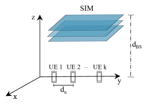
In this section, numerical simulations are provided to evaluate the performance of the proposed SIM-RSMA system. The BS, positioned at a height of meters, is equipped with N antennas arranged along the x-axis. It utilizes a SIM to perform wave-domain beamforming. The SIM’s layered structure lies parallel to the x-y plane, with all antennas or meta-atoms aligned along the z-axis, ensuring coordinated beam control across the aperture. Moreover, users are evenly spaced on the y-axis by of 10 m as illustrated in Fig. 2. The system operates at a carrier frequency of 28 GHz. The SIM consists of metasurface layers, each with meta-atoms arranged in a square grid of size . The spacing between adjacent meta-atoms within each layer is set to , and the total SIM thickness is , with an inter-layer spacing of . The noise power at each user is , and the distance-dependent path loss is modeled as , where , , and [7]. Unless otherwise mentioned, the parameters used in the simulation are as follows: the number of SIM elements per layer is , the number of users , and the power budget dBm.
We evaluate the proposed SIM-RSMA scheme against five benchmark schemes: (1) SIM-SDMA that applies private message transmission only, with optimized power allocation and SIM beamforming, (2) SIM-NOMA that uses power-domain multiplexing with SIC decoding [11], assisted by SIM-based analog beamforming, (3) RSMA-UPA that applies RSMA with uniform power allocation and optimized SIM phase shifts, (4) SDMA-UPA that applies SDMA with uniform power allocation and optimized SIM beamforming, and (5) RSMA-Random that evaluates RSMA with optimized power allocation and randomly generated SIM phase shifts.
Fig. 5 presents the average minimum rate achieved as a function of transmit power. At , SIM-RSMA achieves approximately 22% and 105% higher minimum rate than SIM-SDMA and SIM-NOMA, respectively. These gains are attributed to RSMA’s capability to partially decode interference via the common stream, offering more flexible interference management than SDMA, which treats interference as noise, and NOMA, which relies on strict decoding order and user channel disparity. Uniform power allocation in RSMA and SDMA leads to noticeable performance degradation, while RSMA with random SIM beamforming performs worst, highlighting the need for joint power and phase shift optimization.
Fig. 5 shows the average minimum rate versus the number of meta-atoms per SIM layer . At , the proposed SIM-RSMA scheme with achieves approximately 40% and 68% higher minimum rate than SIM-SDMA and SIM-NOMA, respectively. Also, the performance consistently improves as the number of SIM layers increases. A significant gain is achieved when increases from 1 to 2, and although the additional improvement from 2 to 3 layers is relatively smaller, it remains beneficial and contributes to overall system enhancement.. These gains result from the additional degrees of freedom offered by adding more layers to the SIM, which enhance spatial transformations and improve wave-domain beamforming. RSMA benefits more from this capability due to its flexible interference management via common and private stream superposition, unlike SDMA and NOMA, which rely on more rigid spatial or power-domain strategies.
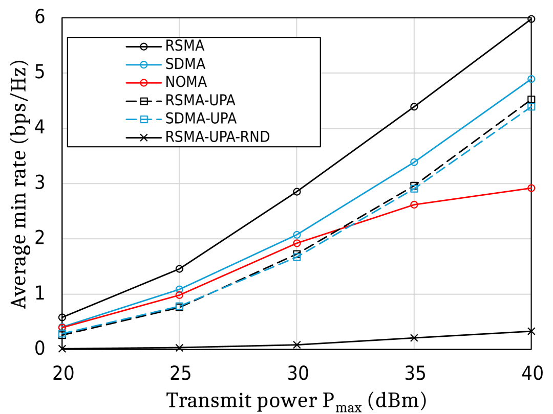
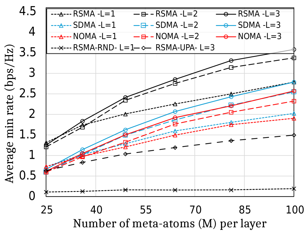
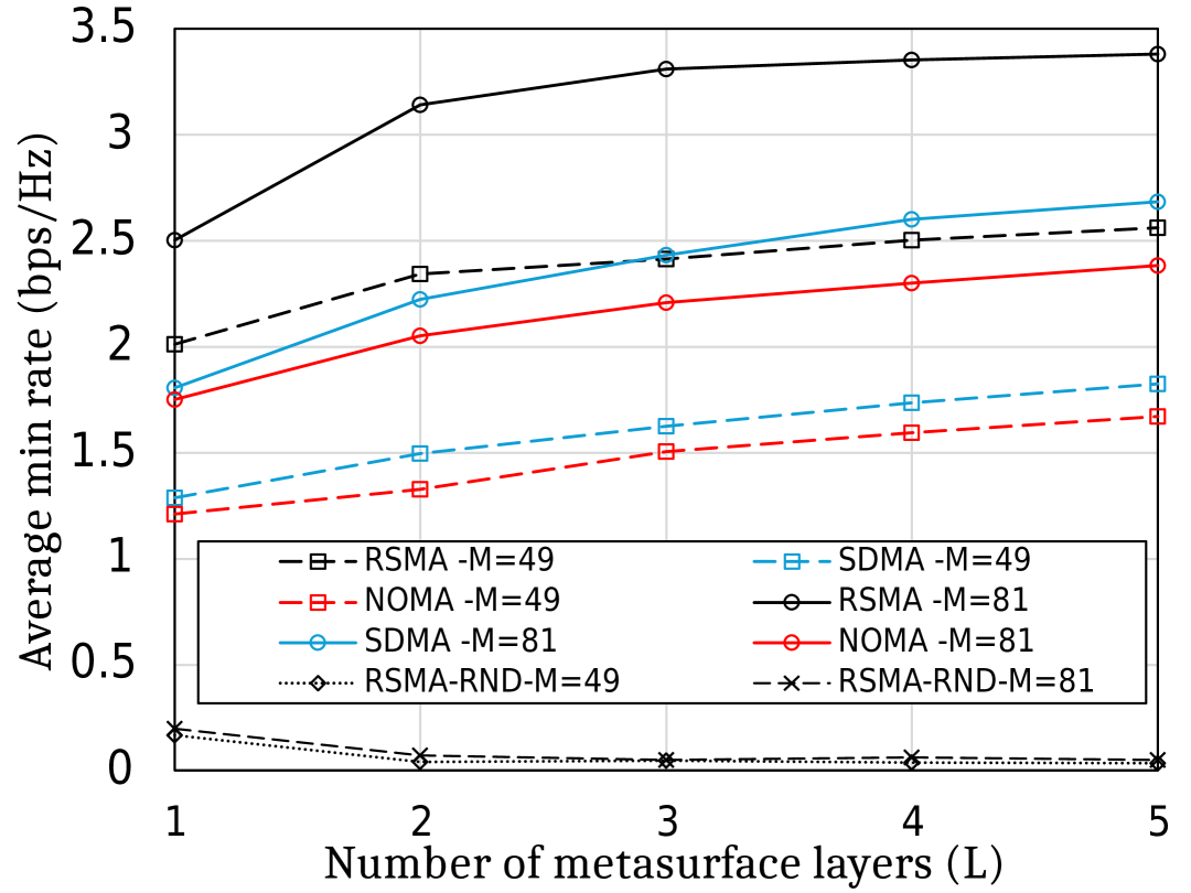
Fig. 5 presents the average minimum rate as a function of the number of SIM layers . SIM-RSMA scheme achieves approximately 38% and 64% higher minimum rate than SIM-SDMA and SIM-NOMA, respectively, at and . Increasing the number of layers improves performance due to enhanced spatial transformation capabilities. However, the gain from increasing from 1 to 2 is noticeably larger than the gain from increasing from 4 to 5, indicating diminishing returns as the SIM approaches its wave manipulation capacity. Once sufficient angular resolution and spatial separation are achieved, additional layers yield marginal improvements. Moreover, higher minimum rates are observed with larger numbers of meta-atoms per layer, which indicates the inherent trade-off between increasing the number of layers and expanding the aperture size for effective SIM design.
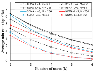
Fig. 6 shows the impact of increasing the number of users on the average minimum rate. As expected, the minimum rate decreases as increases due to higher interference and reduced spatial degrees of freedom. At , the proposed SIM-RSMA scheme with , achieves 29% and 50% higher minimum rate compared to SIM-SDMA and SIM-NOMA, respectively. Increasing the number of meta-atoms improves performance across all schemes, particularly in dense-user regimes. However, with a small metasurface configuration (), SIM-SDMA and SIM-NOMA converge to similar performance. This is attributed to the increased correlation between the user’s channels and the limited available degrees of freedom or spatial resources. With only 64 elements, the metasurface’s ability to effectively differentiate or allocate resources is limited. As a result, both SIM-SDMA and SIM-NOMA may struggle to fully leverage their respective advantages. Additionally, we observe that distributing meta-atoms over two layers yields higher minimum rates than placing meta-atoms in a single-layer configuration. This is because the multi-layer configuration enables more effective spatial separation of the users’ signals through successive phase transformations in the wave domain, even with the same number of total elements.
V Conclusion
In this paper, we investigated the integration of RSMA with a SIM for downlink multiuser MISO systems, focusing on a max–min fairness design. By leveraging SIM’s programmable wave-domain beamforming and 1-layer RSMA strategy, we formulated a max–min rate optimization problem and addressed its non-convexity via an AO framework. Specifically, the power allocation was handled through SCA, while SIM beamforming was optimized using the RCG method. Numerical results demonstrated that the proposed SIM-RSMA framework achieves higher minimum rates compared to SIM-NOMA and SIM-SDMA. These results demonstrate the potential of combining RSMA and SIM to enhance user fairness and maximize the minimum user rate in multiuser MISO systems.
References
- [1] W. Saad, M. Bennis, and M. Chen, “A vision of 6G wireless systems: Applications, trends, technologies, and open research problems,” IEEE Netw., vol. 34, no. 3, pp. 134–142, 2020.
- [2] L. You, J. Xiong, D. W. K. Ng, C. Yuen, W. Wang, and X. Gao, “Energy efficiency and spectral efficiency tradeoff in RIS-aided multiuser MIMO uplink transmission,” IEEE Trans. Signal Process., vol. 69, pp. 1407–1421, 2021.
- [3] X. Yu, D. Xu, Y. Sun, D. W. K. Ng, and R. Schober, “Robust and secure wireless communications via intelligent reflecting surfaces,” IEEE J. Sel. Areas Commun., vol. 38, no. 11, pp. 2637–2652, 2020.
- [4] X. Lin, Y. Rivenson, N. T. Yardimci, M. Veli, Y. Luo, M. Jarrahi, and A. Ozcan, “All-optical machine learning using diffractive deep neural networks,” Science, vol. 361, no. 6406, pp. 1004–1008, 2018.
- [5] J. An, C. Xu, D. W. K. Ng, G. C. Alexandropoulos, C. Huang, C. Yuen, and L. Hanzo, “Stacked intelligent metasurfaces for efficient holographic mimo communications in 6G,” IEEE J. Sel. Areas Commun., vol. 41, no. 8, pp. 2380–2396, 2023.
- [6] N. Stefan Perović and L.-N. Tran, “Mutual information optimization for SIM-based holographic MIMO systems,” IEEE Commun. Lett., vol. 28, no. 11, pp. 2583–2587, 2024.
- [7] Y. Hu, J. Zhang, E. Shi, Y. Lu, J. An, C. Yuen, and B. Ai, “Joint beamforming and power allocation design for stacked intelligent metasurfaces-aided cell-free massive MIMO systems,” IEEE Trans. Veh. Technol., vol. 74, no. 3, pp. 5235–5240, 2025.
- [8] J. An, M. D. Renzo, M. Debbah, H. Vincent Poor, and C. Yuen, “Stacked intelligent metasurfaces for multiuser downlink beamforming in the wave domain,” IEEE J. Sel. Areas Commun., pp. 1–1, 2025.
- [9] H. Niu, J. An, A. Papazafeiropoulos, L. Gan, S. Chatzinotas, and M. Debbah, “Stacked intelligent metasurfaces for integrated sensing and communications,” IEEE Wireless Commun. Lett., vol. 13, no. 10, pp. 2807–2811, 2024.
- [10] B. Clerckx, H. Joudeh, C. Hao, M. Dai, and B. Rassouli, “Rate splitting for MIMO wireless networks: a promising PHY-layer strategy for LTE evolution,” IEEE Commun. Mag., vol. 54, no. 5, pp. 98–105, 2016.
- [11] Y. Mao, B. Clerckx, and V. Li, “Rate-splitting multiple access for downlink communication systems: Bridging, generalizing and outperforming SDMA and NOMA,” EURASIP Journal on Wireless Communications and Networking, vol. 2018, 05 2018.
- [12] Q. Wu, S. Zhang, B. Zheng, C. You, and R. Zhang, “Intelligent reflecting surface-aided wireless communications: A tutorial,” IEEE Trans. Commun., vol. 69, no. 5, pp. 3313–3351, 2021.
- [13] A. Bansal, K. Singh, B. Clerckx, C.-P. Li, and M.-S. Alouini, “Rate-splitting multiple access for intelligent reflecting surface aided multi-user communications,” IEEE Trans. Veh. Technol., vol. 70, no. 9, pp. 9217–9229, 2021.
- [14] Y. Sun, K. An, M. Yu, Y. Hu, Y. Zhu, Z. Lin, M. Xiao, N. Al-Dhahir, D. Niyato, and J. Wang, “Dual-polarized stacked metasurface transceiver design with rate splitting for next-generation wireless networks,” IEEE J. Sel. Areas Commun., vol. 43, no. 3, pp. 811–833, 2025.
- [15] Q. Huai, Y. Liang, and W. Yuan, “Stacked intelligent metasurfaces-aided rate splitting multiple access system,” IEEE Wireless Communications Letters, pp. 1–1, 2025.
- [16] E. Björnson and L. Sanguinetti, “Rayleigh fading modeling and channel hardening for reconfigurable intelligent surfaces,” IEEE Wireless Commun. Lett., vol. 10, no. 4, pp. 830–834, 2021.
- [17] M. Grant and S. Boyd, “CVX: Matlab software for disciplined convex programming, version 2.1,” http://cvxr.com/cvx, Mar. 2014.
- [18] P.-A. Absil, R. Mahony, and R. Sepulchre, Optimization Algorithms on Matrix Manifolds, 12 2008, vol. 78.
- [19] M. Katwe, K. Singh, B. Clerckx, and C.-P. Li, “Rate-splitting multiple access and dynamic user clustering for sum-rate maximization in multiple RISs-aided uplink mmWave system,” IEEE Trans. Commun., vol. 70, no. 11, pp. 7365–7383, 2022.