Robustness of Bound States in the Continuum in Bilayer Structures against Symmetry Breaking
Abstract
We investigate the robustness of bound states in the continuum (BICs) in a bilayer dielectric rod array against geometric and material perturbations. Our analysis focuses on both symmetry-protected and Fabry-Pérot BICs, examining their transformation into quasi-BICs under three structural modifications: (i) in-plane displacement of one layer, which breaks the symmetry of the system; (ii) introduction of material losses that break time-reversal symmetry; and (iii) variation in the interlayer distance, which preserves structural symmetry. In particular, we demonstrate that material losses inevitably induce radiation in Fabry-Pérot BICs via second-order perturbation processes, converting them into quasi-BICs, while symmetry-protected BICs remain non-radiative. We further show that, despite the inherent instability of BICs under symmetry-breaking effects, their resilience can be significantly enhanced through proper design. Both Fabry-Pérot and symmetry-protected BICs exhibit exponentially weak sensitivity to -breaking perturbations as the interlayer distance increases. Our findings pave the way for the development of BIC-based photonic devices with improved robustness against fabrication imperfections, environmental variations, and material losses.
I Introduction
Bound states in the continuum (BIC) are non-radiating states that exist within the continuum spectrum of radiating modes in the surrounding space [1, 2]. The radiative factor of BICs diverges; however, in real systems, BICs transform into quasi-BICs (qBICs) exhibiting a finite radiative lifetime and a finite radiative factor [2, 3]. The radiative factor of quasi-BICs (qBICs) can be precisely tuned through controllable symmetry breaking in the structure or by adjusting the angle of incidence [4, 5]. By adjusting the radiative factor of quasi-BICs, one can achieve the critical coupling regime, in which the radiative and non-radiative losses are perfectly balanced. This results in maximum field enhancement, which is important for many applications, including sensing [6, 7, 8], lasing [9, 10, 11], nonlinear optics [12, 13, 14], and polaritonics [15, 16, 17, 18, 19, 20].
In periodic photonic structures, BICs are typically classified into (i) symmetry-protected BICs [21, 22] and (ii) accidental BICs [23, 24]. The coupling of symmetry-protected BICs to open scattering channels is forbidden due to the selection rules, i.e. the mismatch between the symmetry of the mode and the radiating waves. In contrast, to avoid coupling of accidental BICs to open scattering channels, the geometric or material parameters of the system should be precisely tuned. The simplest example of accidental BIC is a Fabry-Pérot BIC (FP-BIC), which is formed in an effective 1D system composed of two identical resonant scatterers, i.e. mirrors that perfectly reflect waves at the resonant frequency. FP-BICs appear when the distance between the scatterers satisfies the Fabry-Pérot quantization condition at the resonant frequency of the mirrors. Resonant mirrors can be formed by gratings, metasurfaces, or even the upper and lower interfaces of a photonic crystal slab [25, 26, 27, 28, 29, 30].
FP-BICs have been extensively studied in a variety of photonic systems [31, 32, 33, 34, 35, 36, 37, 38]. The symmetry of metasurfaces or gratings was demonstrated to play a crucial role in the formation of FP-BICs. Ndangali and Shabanov were the first to provide a detailed analysis of FP-BICs in bilayer gratings and their robustness to symmetry breaking, supporting the analysis with a deep mathematical foundation [38]. It is shown that a double-layer wavy grating form a Fabry-Pérot cavity that hosts FP-BICs [32]. Moreover, Nabol et al. [33] demonstrated that an anisotropic photonic crystal with two anisotropic defect layers can support FP-BICs, with an analytic solution explaining spectral features such as avoided crossings and resonance collapses, which enables the design of microcavities with controllable factors. The tuning of FP-BICs is also influenced by parameters such as the distance between layers and asymmetry in periodic structures [34, 35]. In some cases, symmetry-breaking effects prevent the formation of FP-BICs, even when total reflection conditions are met, illustrating that perfect total reflection does not always guarantee the emergence of FP-BICs [35]. The sensitivity of FP-BICs to system parameters can be harnessed for dynamic control of their factor through adjustments such as phase detuning and structural modifications [34]. These findings emphasize that symmetry is essential in the formation and manipulation of FP-BICs, suggesting that the influence of symmetry on these phenomena remains an ongoing topic of active research and discussion [36].
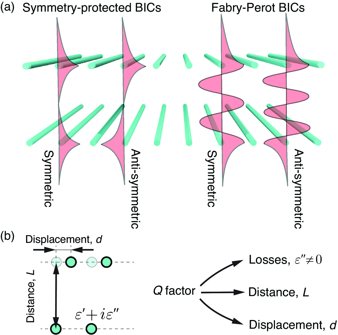
In this paper, we present a comprehensive analysis of the factor for both symmetry-protected and FP-BICs in a bilayer periodic array of infinitely long dielectric rods [Fig. 1(a)]. We analyze the effect of material losses (T-symmetry breaking), variations in the interlayer distance, and in-plane displacement of one layer (C2-symmetry breaking) [Fig. 1(b)]. We analytically reveal how material losses affect FP-BICs and show that absorption not only leads to dissipative losses, but also induces additional radiative leakage as a second-order perturbation effect, thereby transforming FP-BICs into quasi-FP-BICs with a finite radiative lifetime. In contrast, symmetry-protected BICs remain robust against material losses. Furthermore, we demonstrate that for a fixed material loss, the factor of symmetry-protected BICs is largely insensitive to variations in the interlayer distance, whereas the factor of FP-BICs increases linearly with the distance between the layers. We also demonstrate that despite the inherent instability of BICs under C2-symmetry-breaking, their resilience can be significantly enhanced through design optimization. Specifically, both FP and symmetry-protected BICs exhibit exponentially weak sensitivity to C2-breaking perturbations as the interlayer distance increases.
II Theoretical background
II.1 Infinite array of dielectric rods
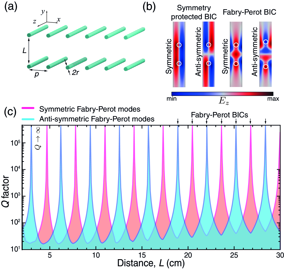
We consider a metasurface consisting of two identical periodic arrays of infinitely long parallel dielectric rods [Fig. 2(a)]. The radius of the rods is cm and the period is cm. Thus, the unit cell of the structure contains two rods placed at a distance from each other. The permittivity of the rods is , which corresponds to low-loss polymers, such as Teflon in the frequency range of 0.1-10 GHz. The structure supports two types of BIC: (i) FP-BICs [39, 40, 41, 33] and (ii) symmetry-protected BICs [42, 43, 44]; see Appendix A for more details on the connection between Bloch theorem and different types of BICs. We limit our analysis to the case of TE-polarized modes [] assuming .
Since symmetry-protected BICs exist independently in each single-layer structure, in the bilayer configuration, they couple via the near field, forming symmetric and anti-symmetric symmetry-protected BICs [see Fig. 2(b); we deeply discussed symmetry of the modes in Appendix B]. Varying the interlayer distance preserves the mirror symmetry of the structure and does not destroy these BICs. In contrast, FP-BICs emerge only at specific distances that satisfy Fabry-Pérot quantization conditions at frequencies near the resonant frequency of the single-layer metasurface. Figure 2(c) shows the dependence of the factor of the FP-BICs on the interlayer distance : the factor varies from infinity to several tens, illustrating the extreme sensitivity of FP-BICs to changes in . As variations in preserve the -mirror symmetry, both FP-BICs and symmetry-protected BICs can be considered as symmetric or anti-symmetric with respect to the transformation .
II.2 Coupled mode theory
II.2.1 Single-layer structure
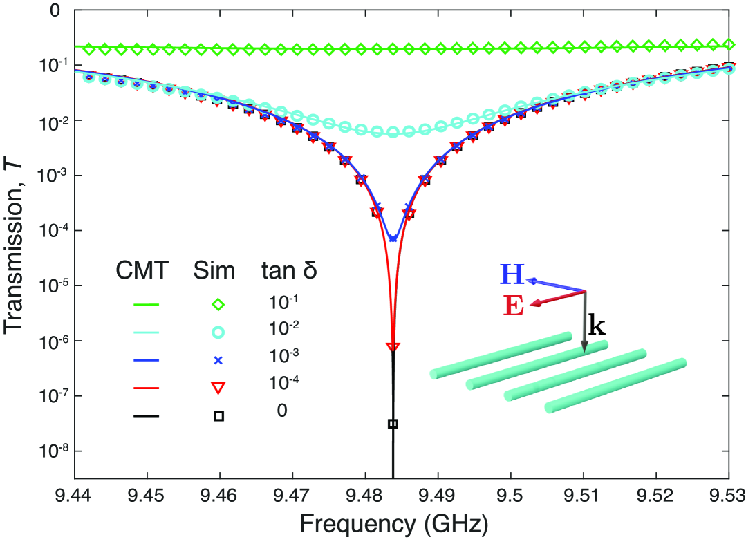
FP-BICs are formed similarly to resonances in a Fabry-Pérot resonator, where the field is confined between two mirrors. Therefore, to analytically describe FP-BICs in our bilayer configuration, first, we need to study the single-layer structure and analyze its transmission spectrum. The solid lines in Fig. 3 show the transmission spectra of the single-layer structure numerically calculated using COMSOL for a normally incident TE-polarized plane wave for different material losses varying from 0 to 10-1. The structure exhibits a pronounced resonant behavior near the frequency 9.48 GHz, where the transmission spectrum has a sharp minimum. For the lossless case, the transmission becomes zero, and the structure behaves as a perfect mirror; when we introduce material losses, the structure becomes partially transparent.
The transmission spectra for a single layer can be well described using the temporal coupled mode theory (CMT) [45]. Indeed, in terms of CMT, our structure is a single-mode resonator coupled to two ports corresponding to plane waves above and beneath the layer. The amplitude reflection () and transmission () coefficients can be written as follows (see Appendix D for derivation details):
| (1) |
| (2) |
Here, is the resonant frequency, and and are the radiative and non-radiative inverse lifetimes of the resonance mode, respectively. Since CMT is a phenomenological framework, the values of , , and are obtained from the numerical solution of the eigenvalue problem in COMSOL. The main challenge lies in distinguishing and from the total decay rate calculated numerically. Noting that when , the absorption losses can be determined as a function of the material loss tangent by the relation . Our analysis shows that the absorption losses are almost proportional to the material loss tangent over a wide range of material losses.
The markers in Fig. 3 indicate the transmission spectra calculated using CMT [see Eq. (2)], which are in good agreement with the results of numerical simulations. Furthermore, Eq. (2) implies that at the resonant frequency, the transmission behaves as
| (3) |
From this relation, one can immediately conclude that FP-BICs are destroyed by material losses. Indeed, when , the transmission becomes nonzero at the resonant frequency, indicating that the FP-BIC transforms into a quasi-FP-BIC with finite radiative losses.
II.2.2 Bilayer structure
Equations (1) and (2) fully describe the scattering matrix of the single-layer structure. The scattering matrix of the double-layer system can be obtained either by applying the Redheffer star product [46] or by explicitly accounting for multiple reflections between the layers. The real-valued poles of the scattering matrix correspond to the formation of FP-BICs. Alternatively, the eigenfrequency condition for the bilayer structure can be derived by requiring that, after a round trip between the layers, the amplitude of the mode remains the same and the accumulated phase changes by , where is an integer [47]. This condition can be written as
| (4) |
This equation can also be derived using the effective Hamiltonian approach, neglecting the near-field coupling between the layers (see Appendix C). Substituting Eq. (1) into Eq. (4) yields the characteristic equation for the eigenfrequencies:
| (5) |
Here “” corresponds to an odd mode and “” to an even one. This transcendent equation defines the resonances and their factors in the bilayer structure as a function of , , and . It can be solved numerically or using the perturbation theory. It is worth mentioning that this equation does not describe the symmetry-protected BICs.
First, we set and find the distances ensuring the existence of FP-BICs. It can be shown that Eq. (5) admits real solutions for distances that satisfy the Fabry-Perot quantization condition
| (6) |
where is the number of FP-BICs. Odd values of (i.e., ) correspond to even FP-BICs, and even values of (i.e., ) correspond to odd FP-BICs. It is worth mentioning that, in contrast to a conventional Fabry-Pérot resonator, where the reflection coefficient of the mirrors is typically frequency-independent, the use of resonant mirrors introduces strong frequency dependence. In this case, only a single high- mode is supported, which can be clearly identified in the spectrum due to its sharp and isolated resonance feature.
II.3 Q factor, finesse, and mode volume
The deviation in from and destroys the FP-BICs transforming them into quasi FP-BICs with finite factors. The total factor reads
| (7) |
Here corresponds to the radiation due deviation of the interlayer distance from ; corresponds the absorption induced by ; corresponds to the radiative losses induced .
Assuming that and in Eq. (5), one can get analytical expressions for the factors:
| (8) |
| (9) |
| (10) |
Here, denotes the finesse of the Fabry-Pérot resonance, while represents the one-dimensional effective mode volume normalized to half wavelength. The normalized displacement is given by . The one-dimensional effective mode volume is defined as
| (11) |
This expression differs from that of a conventional Fabry-Pérot resonator by the presence of an additional term, which arises due to the resonant nature of the mirrors. In the classical model of a Fabry-Pérot resonator with non-resonant mirrors, reflection is assumed to occur instantaneously, and the photon dwell time at the mirrors is negligible. In contrast, the mirrors considered in our system support resonances with a finite radiative lifetime . As a result, photons are not reflected instantaneously but are temporarily trapped within the mirrors. This delayed reflection can be interpreted as an effective increase in the photon path length, equivalent to extending the physical distance between the mirrors by an additional length . Consequently, two limiting regimes can be identified: (i) a short-arm Fabry–Pérot resonator, where and the photon energy is predominantly confined within the resonant mirrors; and (ii) a long-arm Fabry–Pérot resonator, where and the energy is mainly stored in the cavity space between the mirrors.
III Effect of material losses
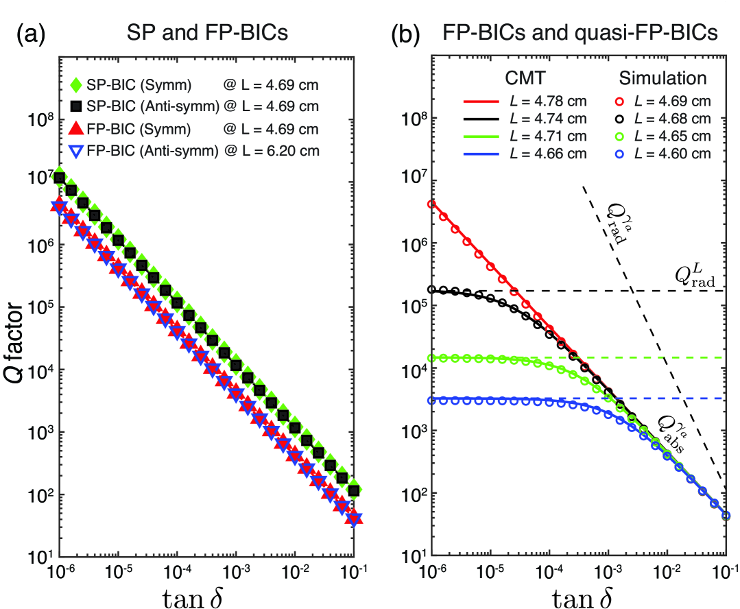
Let us analyze the impact of material losses on the symmetry-protected BICs (, ). Since the introduction of material absorption does not break the symmetry of the system, these BICs persist but acquire a finite factor. Figure 4(a) shows the dependence of the total quality factor for symmetry-protected and FP-BICs. For both types of BICs, the absorptive contribution to the total factor follows the relation
| (12) | |||
| (13) |
where denotes the optical confinement factor of the mode [48]. In our case, due to the low refractive index and sparse geometry of the structure, is approximately 0.1 for all BICs under consideration. In contrast, for structures composed of high-index materials such as ceramics or water, the confinement factor approaches unity (), which significantly limits the achievable -factors [49, 50].
Figure 4(b) shows the dependence of the quality factor for FP-BICs and quasi-FP-BICs that arise when the interlayer distance is detuned from the optimal value , defined by the quantization condition in Eq. (6). The solid lines represent the results obtained from CMT, while the markers indicate data from full-wave numerical simulations (COMSOL). A good agreement between the analytical and numerical results is observed. The dashed lines depict the contributions of different loss mechanisms to the total -factor given by Eqs. (8), (9), and (10). At small values of the loss tangent , the radiative losses dominate, whereas for larger , absorption becomes the primary loss mechanism for quasi-FP-BICs. The regime of critical coupling corresponds to the condition where radiative and non-radiative losses are balanced, leading to maximum field enhancement. This condition can be derived analytically from Eqs. (9) and (10) and is expressed as:
| (14) |
As discussed in Sec. II.2.1, FP-BICs are inherently non-robust with respect to material losses. The presence of absorption makes the resonant mirrors partially transparent, preventing perfect confinement of the mode and thereby transforming the FP-BIC into a quasi-FP-BIC [see Eq. (3)]. This instability arises from the fact that an FP-BIC, as an accidental BIC, is inherently sensitive to time-reversal symmetry breaking, and, therefore, it is generally eliminated in the presence of material loss [51, 3]. However, the radiative losses induced by material absorption appear only as a second-order correction, such that the associated radiative -factor scales as [see Eq. (8)]. Consequently, these induced radiative losses remain almost negligible over a broad range of [see the corresponding dashed line in Fig. 4(b)].
IV Effect of distance
Let us analyze how the interlayer distance between the resonant mirrors influences the radiative and absorption losses of symmetry-protected and Fabry-Pérot BICs in the bilayer structure. As a representative case, we fix the loss tangent at .
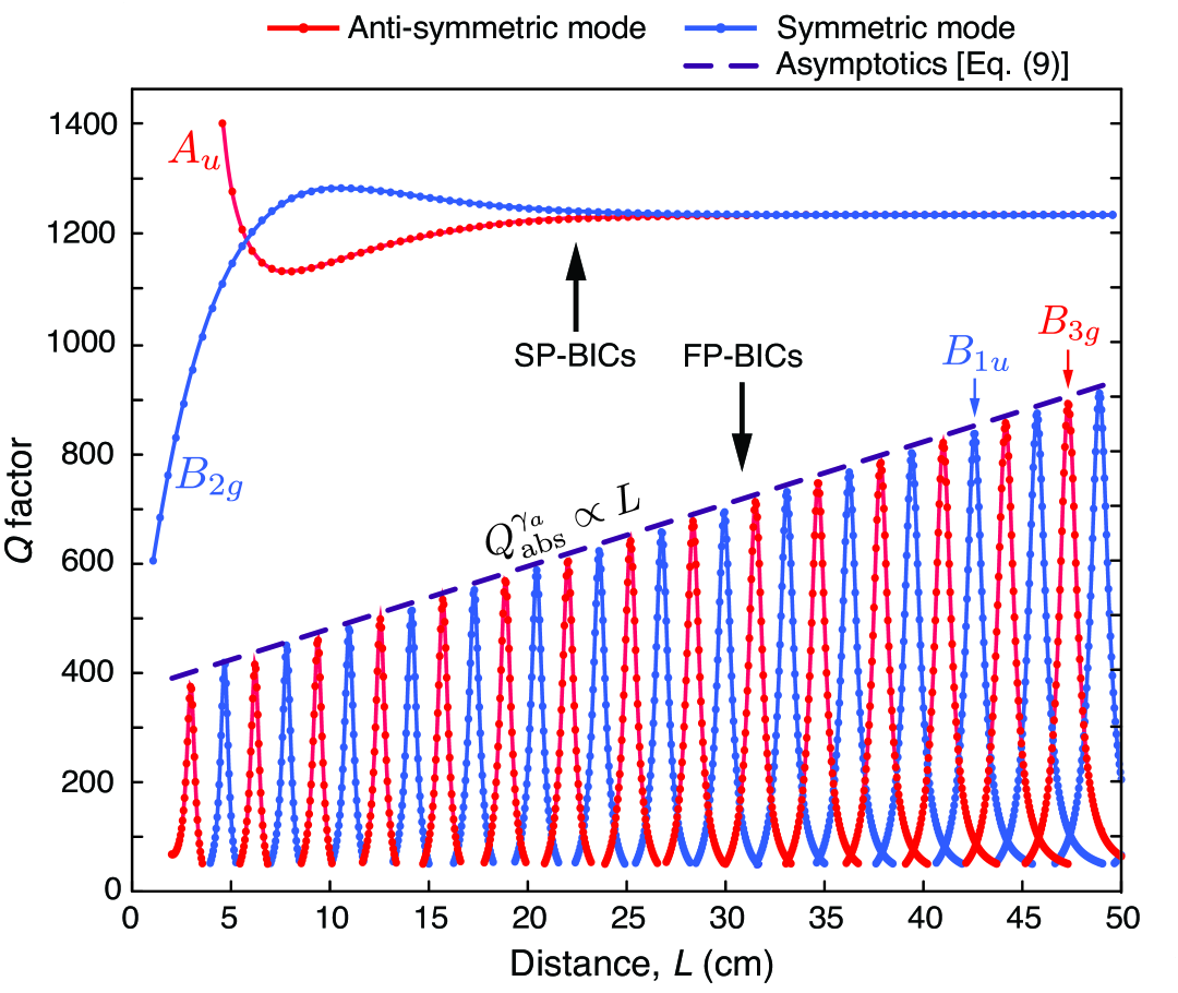
At small interlayer distances, symmetry-protected BICs localized in each layer interact via near-field, which modifies the mode profiles and their overlap with the absorbing material. This interaction leads to oscillatory behavior of the -factor as a function of , as shown in Fig. 5. In particular, for small values of , the symmetric BIC () exhibits stronger field confinement inside the dielectric rods, resulting in increased absorption losses. In contrast, the anti-symmetric BIC () has a weaker overlap with the rods, yielding lower losses and lower effective mode index, i.e., the blue spectral shift. When cm, this frequency enters the domain of opening diffraction orders, thereby destroying the BIC. As the distance increases, the near-field interaction becomes negligible for , and the symmetry-protected BICs in each layer effectively decouple. Consequently, the factors of both symmetric and anti-symmetric symmetry-protected BIC become independent of (see Fig. 5).
Fabry-Pérot BICs exhibit fundamentally different behavior. Their electromagnetic energy is confined within the resonant mirrors and in the cavity region between them. As the interlayer distance increases, the energy stored between the mirrors grows linearly, while the material losses – occurring solely within the mirrors – remain constant. This results in a linear increase in the -factor of FP-BICs with respect to . Consequently, the -factor of FP-BICs can become arbitrarily large, even in systems with material absorption. The analytical model described by Eq. (9) shows excellent agreement with the numerical results obtained using COMSOL, as illustrated by the violet dashed line in Fig. 5.
It is also important to note that variations in the inter-mirror distance lead to spectral shifts of the Fabry-Pérot modes. For small normalized displacements, , the resonant frequency can be approximated as
| (15) |
Notably, corrections to the imaginary part of arise only in the second-order perturbation theory with respect to .
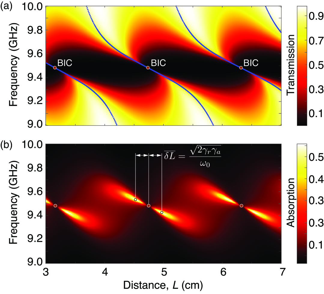
Figure 6 presents the transmission [panel (a)] and absorption [panel (b)] spectra of the bilayer structure as functions of the interlayer distance . The blue solid lines in panel (a) indicate the spectral positions of the Fabry-Pérot resonances. As shown in panel (b), the absorption exhibits pronounced maxima at specific values of , corresponding to the critical coupling condition defined by Eq. (14). Although critical coupling enhances absorption, it does not reach unity due to radiation occurring in both upward and downward directions. At the BIC positions, absorption remains finite but extremely small, since the effective radiative losses introduced by absorption scale as [see Eq. (8)].
V Effect of displacement
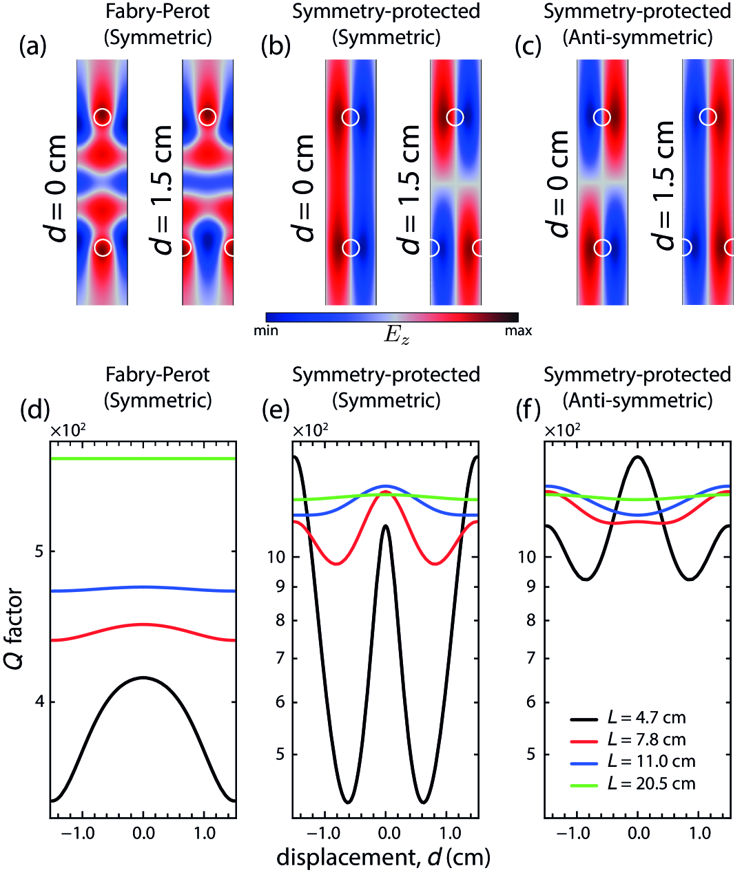
In a bilayer system, the factor of BICs depends on the relative alignment of the layers. Indeed, as mentioned before, FP-BICs are not robust to variations in the interlayer distance [Fig. 5]. Let us shift the bottom layer along its axis of periodicity [Fig. 1(b)]. Such a perturbation preserves the inversion symmetry and does not result in bianisotropic response [52]. We introduce the in-plane displacement cm. To better illustrate the effect and deal with finite factors, we also fix a loss tangent . The factor of the symmetric FP-BIC decreases monotonically with increasing displacement [Fig. 7(d)]. Notice that the decrease rate varies for different interlayer distances . The wavefront between layers comprises a superposition of waves scattered on each rod in the first layer. Nevertheless, as the distance between the layers increases, the wavefront incident on the second layer becomes a plane wave, enhancing the stability of the factor to the displacement of the layer along the periodicity axis. We also show the field distributions for cm and cm [Fig. 7(a)–(c)].
For both symmetry-protected BICs, two maxima of the factor are observed at cm and cm [Fig. 7(e),(f)]. The factor of the mode at cm matches that of the mode at cm, and vice versa. Remarkably, the field distributions for these modes are quite similar [Fig. 7(b),(c)]. Crucially, for the displacement values mentioned above (zero or half-period), the resonators preserve symmetry, essential for the formation of symmetry-protected BICs. However, even a small offset from these displacement values breaks the symmetry, reducing the factors.
VI Conclusions
In conclusion, we have addressed how material and geometric perturbations affect the factor of symmetry-protected and Fabry-Pérot quasi-BICs in a bilayer periodic array of infinitely long dielectric rods. We have determined that introducing material losses into structural elements significantly impacts the factor for both types of BICs. The study distinguishes and compares the contributions of different loss mechanisms to the factor of FP-BICs. In particular, absorption reduces the factor of the resonator more significantly than other loss types. For symmetry-protected BICs with a fixed loss tangent, the factor remains unaffected by changes in the interlayer distance. In contrast, an increased interlayer distance increases the factor for FP-BICs. Furthermore, shifting one layer by half the period does not alter the factor of FP-BICs, but it significantly decreases the factor of symmetry-protected BICs. BICs also become less sensitive to C2-breaking perturbations as the interlayer distance increases. In general, our results underscore the intricate interplay between material losses, geometry, and the resulting factors for different BIC types in the analyzed system.
Acknowledgements.
We acknowledge the support of the Russian Science Foundation (grant No 25-12-00213). The authors thank Lydia Pogorelskaya for her proofreading of the English manuscript.References
- von Neumann and Wigner [1929] J. von Neumann and E. P. Wigner, Über merkwürdige diskrete eigenwerte, Z. Phys. 30, 465 (1929).
- Koshelev et al. [2020a] K. Koshelev, Y. Kivshar, and A. Bogdanov, Engineering with bound states in the continuum, Opt. Photonics News 31, 38 (2020a).
- Hsu et al. [2013a] C. W. Hsu, B. Zhen, J. Lee, S.-L. Chua, S. G. Johnson, J. D. Joannopoulos, and M. Soljačić, Observation of trapped light within the radiation continuum, Nature 499, 188 (2013a).
- Kühne et al. [2021] J. Kühne, J. Wang, T. Weber, L. Kühner, S. A. Maier, and A. Tittl, Fabrication robustness in bic metasurfaces, Nanophotonics 10, 4305 (2021).
- Maslova et al. [2021] E. E. Maslova, M. V. Rybin, A. A. Bogdanov, and Z. F. Sadrieva, Bound states in the continuum in periodic structures with structural disorder, Nanophotonics 10, 4313 (2021).
- Romano et al. [2018] S. Romano, G. Zito, S. Torino, G. Calafiore, E. Penzo, G. Coppola, S. Cabrini, I. Rendina, and V. Mocella, Experimental realization of bound states in the continuum in photonic crystal waveguides, Photonics Res. 6, 726 (2018).
- Srivastava et al. [2019] Y. K. Srivastava, R. T. Ako, M. Gupta, M. Bhaskaran, S. Sriram, and R. Singh, Experimental observation of bound states in the continuum, Appl. Phys. Lett. 115, 15 (2019).
- Maksimov et al. [2022] D. N. Maksimov, V. S. Gerasimov, A. A. Bogdanov, and S. P. Polyutov, Bound states in the continuum in photonic structures, Phys. Rev. A 105, 033518 (2022).
- Kodigala et al. [2017] A. Kodigala, T. Lepetit, Q. Gu, B. Bahari, Y. Fainman, and B. Kanté, Lasing action from photonic bound states in the continuum, Nature 541, 196 (2017).
- Yu et al. [2021] Y. Yu, A. Sakanas, A. R. Zali, E. Semenova, K. Yvind, and J. Mørk, Photonic bound states in the continuum for enhanced light-matter interaction, Nat. Photonics 15, 758 (2021).
- Hwang et al. [2021] M.-S. Hwang, H.-C. Lee, K.-H. Kim, K.-Y. Jeong, S.-H. Kwon, K. Koshelev, Y. Kivshar, and H.-G. Park, Bound states in the continuum in photonic systems, Nat. Commun. 12, 4135 (2021).
- Carletti et al. [2018] L. Carletti, K. Koshelev, C. De Angelis, and Y. Kivshar, Giant nonlinear response at the nanoscale driven by bound states in the continuum, Phys. Rev. Lett. 121, 033903 (2018).
- Carletti et al. [2019] L. Carletti, S. S. Kruk, A. A. Bogdanov, C. De Angelis, and Y. Kivshar, High-harmonic generation at the nanoscale boosted by bound states in the continuum, Phys. Rev. Res. 1, 023016 (2019).
- Koshelev et al. [2020b] K. Koshelev, S. Kruk, E. Melik-Gaykazyan, J.-H. Choi, A. Bogdanov, H.-G. Park, and Y. Kivshar, Subwavelength dielectric resonators for nonlinear nanophotonics, Science 367, 288 (2020b).
- Kravtsov et al. [2020] V. Kravtsov, E. Khestanova, F. A. Benimetskiy, T. Ivanova, A. K. Samusev, I. S. Sinev, D. Pidgayko, A. M. Mozharov, I. S. Mukhin, M. S. Lozhkin, Y. V. Kapitonov, A. S. Brichkin, V. D. Kulakovskii, I. A. Shelykh, A. I. Tartakovskii, P. M. Walker, M. S. Skolnick, D. N. Krizhanovskii, and I. V. Iorsh, Nonlinear polaritons in a monolayer semiconductor coupled to optical bound states in the continuum, Light Sci. Appl. 9, 1 (2020).
- Berghuis et al. [2023] A. M. Berghuis, G. W. Castellanos, S. Murai, J. L. Pura, D. R. Abujetas, E. van Heijst, M. Ramezani, J. A. Sánchez-Gil, and J. G. Rivas, Room Temperature Exciton–Polariton Condensation in Silicon Metasurfaces Emerging from Bound States in the Continuum, Nano Lett. 10.1021/acs.nanolett.3c01102 (2023).
- Luo et al. [2025] C. Luo, W. Li, J. Li, Z. Fu, N. Hu, Z. Yu, W. Chang, P. Li, X. Huang, B. Liu, Y. Yang, A. Jin, B. Quan, S. Tian, H. Yang, Y. Guo, and C. Gu, Room-Temperature Exciton Polaritons in Monolayer WS2 Enabled by Plasmonic Bound States in the Continuum, Nano Lett. 25, 4361 (2025).
- Koshelev et al. [2018a] K. L. Koshelev, S. K. Sychev, Z. F. Sadrieva, A. A. Bogdanov, and I. V. Iorsh, Strong coupling between excitons in transition metal dichalcogenides and optical bound states in the continuum, Phys. Rev. B 98, 161113 (2018a).
- Maggiolini et al. [2023] E. Maggiolini, L. Polimeno, F. Todisco, A. Di Renzo, B. Han, M. De Giorgi, V. Ardizzone, C. Schneider, R. Mastria, A. Cannavale, M. Pugliese, L. De Marco, A. Rizzo, V. Maiorano, G. Gigli, D. Gerace, D. Sanvitto, and D. Ballarini, Strongly enhanced light–matter coupling of monolayer WS2 from a bound state in the continuum, Nat. Mater. 22, 964 (2023).
- Weber et al. [2023] T. Weber, L. Kühner, L. Sortino, A. Ben Mhenni, N. P. Wilson, J. Kühne, J. J. Finley, S. A. Maier, and A. Tittl, Intrinsic strong light-matter coupling with self-hybridized bound states in the continuum in van der Waals metasurfaces, Nat. Mater. 22, 970 (2023).
- Ni et al. [2016] L. Ni, Z. Wang, C. Peng, and Z. Li, Tunable optical bound states in the continuum beyond in-plane symmetry protection, Phys. Rev. B 94, 245148 (2016).
- Cong and Singh [2019] L. Cong and R. Singh, Symmetry-protected dual bound states in the continuum in metamaterials, Adv. Opt. Mater. 7, 1900383 (2019).
- Plotnik et al. [2011] Y. Plotnik, O. Peleg, F. Dreisow, M. Heinrich, S. Nolte, A. Szameit, and M. Segev, Experimental observation of optical bound states in the continuum, Phys. Rev. Lett. 107, 183901 (2011).
- Koshelev et al. [2018b] K. Koshelev, S. Lepeshov, M. Liu, A. Bogdanov, and Y. Kivshar, Asymmetric metasurfaces with high-q resonances governed by bound states in the continuum, Phys. Rev. Lett. 121, 193903 (2018b).
- Suh et al. [2005a] W. Suh, O. Solgaard, and S. Fan, Displacement sensing using evanescent tunneling between guided resonances in photonic crystal slabs, J. Appl. Phys. 98 (2005a).
- Hsu et al. [2013b] C. W. Hsu, B. Zhen, S.-L. Chua, S. G. Johnson, J. D. Joannopoulos, and M. Soljačić, Bloch surface eigenstates within the radiation continuum, Light Sci. Appl. 2, e84 (2013b).
- Anguiano et al. [2014] S. Anguiano, G. Rozas, A. E. Bruchhausen, A. Fainstein, B. Jusserand, P. Senellart, and A. Lemaître, Spectra of mechanical cavity modes in distributed bragg reflector based vertical gaas resonators, Phys. Rev. B 90, 045314 (2014).
- Bikbaev et al. [2017] R. G. Bikbaev, S. Y. Vetrov, and I. V. Timofeev, Optical tamm states at the interface between a photonic crystal and a gyroid layer, JOSA B 34, 2198 (2017).
- Wu et al. [2022] F. Wu, C. Fan, K. Zhu, J. Wu, X. Qi, Y. Sun, S. Xiao, H. Jiang, and H. Chen, Tailoring electromagnetic responses in a coupled-grating system with combined modulation of near-field and far-field couplings, Phys. Rev. B 105, 245417 (2022).
- Ovcharenko et al. [2020] A. I. Ovcharenko, C. Blanchard, J.-P. Hugonin, and C. Sauvan, Bound states in the continuum in symmetric and asymmetric photonic crystal slabs, Phys. Rev. B 101, 155303 (2020).
- Liu et al. [2009] V. Liu, M. Povinelli, and S. Fan, Resonance-enhanced optical forces between coupled photonic crystal slabs, Opt. Express 17, 21897 (2009).
- Luo and Wu [2022] M. Luo and F. Wu, Wavy optical grating: Wideband reflector and Fabry-P\’erot bound states in the continuum, Phys. Rev. A 106, 063514 (2022).
- Nabol et al. [2022] S. V. Nabol, P. S. Pankin, D. N. Maksimov, and I. V. Timofeev, Fabry-Perot bound states in the continuum in an anisotropic photonic crystal, Phys. Rev. B 106, 245403 (2022).
- Rao et al. [2025] X. Rao, T. He, C. Li, X. Niu, C. Feng, S. Dong, J. Zhu, Z. Wei, Y. Shi, J. Qu, Z. Wang, and X. Cheng, Manipulation of resonances governed by Fabry–Pérot bound states in the continuum, Appl. Phys. Rev. 12, 011423 (2025).
- Mai and Lu [2025] Z. Mai and Y. Y. Lu, Relationship between total reflection and Fabry-Perot bound states in the continuum, Phys. Rev. A 111, 013527 (2025).
- Ni et al. [2024] X. Ni, Y. Liu, B. Lou, M. Zhang, E. L. Hu, S. Fan, E. Mazur, and H. Tang, Three-Dimensional Reconfigurable Optical Singularities in Bilayer Photonic Crystals, Phys. Rev. Lett. 132, 073804 (2024).
- Alagappan et al. [2024] G. Alagappan, F. J. García-Vidal, and C. E. Png, Fabry-Perot Resonances in Bilayer Metasurfaces, Phys. Rev. Lett. 133, 226901 (2024).
- Ndangali and Shabanov [2010] R. F. Ndangali and S. V. Shabanov, Electromagnetic bound states in the radiation continuum for periodic double arrays of subwavelength dielectric cylinders, J. Math. Phys. 51, 102901 (2010).
- Suh et al. [2005b] W. Suh, O. Solgaard, and S. Fan, Displacement sensing using evanescent tunneling between guided resonances in photonic crystal slabs, J. Appl. Phys. 98, 31 (2005b).
- Marinica et al. [2008] D. C. Marinica, A. G. Borisov, and S. V. Shabanov, Bound states in the continuum in photonics, Phys. Rev. Lett. 100, 183902 (2008).
- Suh et al. [2003] W. Suh, M. F. Yanik, O. Solgaard, and S. Fan, Displacement-sensitive photonic crystal structures based on guided resonance in photonic crystal slabs, Appl. Phys. Lett. 82, 1999–2001 (2003).
- Pankin et al. [2020] P. Pankin, D. Maksimov, K.-P. Chen, and I. Timofeev, Fano feature induced by a bound state in the continuum via resonant state expansion, arXiv: Optics,arXiv: Optics 10, 13691 (2020).
- Foley et al. [2014] J. M. Foley, S. M. Young, and J. D. Phillips, Symmetry-protected mode coupling near normal incidence for narrow-band transmission filtering in a dielectric grating, Phys. Rev. B 89, 165111 (2014).
- Foley and Phillips [2015] J. M. Foley and J. D. Phillips, Normal incidence narrowband transmission filtering capabilities using symmetry-protected modes of a subwavelength, dielectric grating, Opt. Lett. 40, 2637 (2015).
- Fan et al. [2003] S. Fan, W. Suh, and J. D. Joannopoulos, Temporal coupled-mode theory for the fano resonance in optical resonators, JOSA A 20, 569 (2003).
- Redheffer [1961] R. Redheffer, Modern Mathematics for the Engineer, edited by E. F. Beckenbach (McGraw-Hill, New York, 1961) Chap. 12.
- Marcuse [1991] D. Marcuse, Theory of Dielectric Optical Waveguides, Quantum Electronics Series (Academic Press, 1991).
- Coldren et al. [2012] L. A. Coldren, S. W. Corzine, and M. L. Mashanovitch, Diode Lasers and Photonic Integrated Circuits, 2nd ed. (John Wiley & Sons, 2012).
- Odit et al. [2021] M. Odit, K. Koshelev, S. Gladyshev, K. Ladutenko, Y. Kivshar, and A. Bogdanov, Observation of supercavity modes in subwavelength dielectric resonators, Adv. Mater. 33, 2003804 (2021).
- Bogdanov et al. [2019] A. A. Bogdanov, K. L. Koshelev, P. V. Kapitanova, M. V. Rybin, S. A. Gladyshev, Z. F. Sadrieva, K. B. Samusev, Y. S. Kivshar, and M. F. Limonov, Bound states in the continuum and fano resonances in the strong mode coupling regime, Adv. Photonics 1, 016001 (2019).
- Zhen et al. [2014a] B. Zhen, C. W. Hsu, L. Lu, A. D. Stone, and M. Soljačić, Topological nature of optical bound states in the continuum, Phys. Rev. Lett. 113, 257401 (2014a).
- Poleva et al. [2023] M. Poleva, K. Frizyuk, K. Baryshnikova, A. Evlyukhin, M. Petrov, and A. Bogdanov, Multipolar theory of bianisotropic response of meta-atoms, Phys. Rev. B 107, L041304 (2023).
- Hsu et al. [2013c] C. W. Hsu, B. Zhen, J. Lee, S.-L. Chua, S. G. Johnson, J. D. Joannopoulos, and M. Soljačić, Observation of trapped light within the radiation continuum, Nature 499, 188–191 (2013c).
- Zhen et al. [2014b] B. Zhen, C. W. Hsu, L. Lu, A. D. Stone, and M. Soljačić, Topological nature of optical bound states in the continuum, Phys. Rev. Lett. 113, 257401 (2014b).
- Bulgakov and Maksimov [2017] E. N. Bulgakov and D. N. Maksimov, Topological bound states in the continuum in arrays of dielectric spheres, Phys. Rev. Lett. 118, 267401 (2017).
- Sakoda [2005] K. Sakoda, Optical properties of photonic crystals, Berlin, Springer (2005).
- Ivchenko et al. [1995] E. Ivchenko, G. Pikus, and G. Skrebtsov, Superlattices and other heterostructures: Symmetry and optical phenomena, Berlin, Springer , 382 (1995).
- Gelessus et al. [1995] A. Gelessus, W. Thiel, and W. Weber, Multipoles and symmetry, Journal of chemical education 72, 505 (1995).
- Sadreev [2021] A. F. Sadreev, Interference traps waves in an open system: bound states in the continuum, Rep. Prog. Phys. 84, 055901 (2021).
- Shabanov [2009] S. V. Shabanov, Resonant light scattering and higher harmonic generation by periodic subwavelength arrays, Int. J. Mod. Phys B 23, 5191 (2009).
- Canós Valero et al. [2025] A. Canós Valero, Z. Sztranyovszky, E. A. Muljarov, A. Bogdanov, and T. Weiss, Exceptional Bound States in the Continuum, Phys. Rev. Lett. 134, 103802 (2025).
- Haus [1984] H. A. Haus, Waves and Fields in Optoelectronics, 1st ed. (Prentice Hall, Englewood Cliffs, NJ, 1984).
Appendix A Bloch theorem
As mentioned above, symmetry is a mathematical condition for the emergence of BIC. According to Bloch’s theorem, the electric field of the eigenmodes in a periodic structure can be expressed as:
| (16) |
where is a periodic function with the same periodicity as the lattice, is the wave vector associated with the propagation of the mode, and is the index of the band, which we omit here for simplicity. This representation illustrates that the electric field is composed of a plane wave component modulated by a periodic function, indicative of the periodicity of the structure.
In such a system, BICs appear only if or . We further limit our analysis to the case of TE-polarized modes [] with . For TE modes, , we can write . The periodic Bloch amplitude can be expanded into the Fourier series as follows:
| (17) |
where is the index of the diffraction channel. At frequencies above the light line (), the mode leaks from the structure to the radiation continuum via the open diffraction channels. BICs arise when leakage into all open diffraction channels is prohibited, which means that the complex Fourier coefficients - the amplitudes of the outgoing waves — are zero. In the subwavelength regime, , only the zeroth diffraction channel remains open. Consequently, the amplitude of the outgoing leaky wave is determined by the zeroth Fourier coefficient , which is defined as the field component averaged over the period: .
For structures exhibiting time-reversal and -rotational symmetries, referred to as , the coefficient becomes purely real for BICs [53, 54, 55]. At the -point (the center of the Brillouin zone), is either an odd or even function, as the photonic structure is -invariant [56, 57].
For an odd function , the zero-order Fourier coefficient vanishes, leading to a symmetry-protected BIC, with coupling to the radiation continuum eliminated due to the structural point symmetry. For an even mode, the spatial average may vanish not only because of symmetry, but also at specific values of geometric and material structural parameters, resulting in the so-called accidental BIC or tunable BIC. In the -point case, these resonances are called Fabry-Pérot BICs.
Appendix B Symmetry of modes
Since the bilayer resonator possesses symmetry, we analyzed the modes of the resonator and classified them according to their point groups using the characteristic table [58]. The symmetric symmetry-protected mode, denoted as , retains , , and inversion symmetries. Further, the anti-symmetric symmetry-protected mode, denoted as , is characterized by symmetry for all orientations. In contrast, the symmetric FP-mode demonstrates , , and symmetries, which means it has symmetry. The anti-symmetric FP-mode possesses symmetry and inversion through a center of symmetry and is denoted as . The summery of the mode classification is presented in Table 1. Hereafter, we use these designations to indicate modes.
| Mode | Representation |
|---|---|
| Symmetry-protected symmetric | |
| Symmetry-protected anti-symmetric | |
| Fabry-Pérot symmetric | |
| Fabry-Pérot anti-symmetric |
Appendix C Effective Hamiltonian approach
Here, we analyze a simple Hamiltonian describing a two-resonance photonic system [59, 60, 61]:
| (18) |
where are the resonance frequencies of the coupled modes, is the near-field internal coupling, are the radiative losses of the modes, and is the phase delay.
If a state is a BIC, then its eigenfrequency must be purely real. Thus, we can write
| (19) |
which leads to the condition
| (20) |
and the eigenvector can be expressed as
| (21) |
Finally, eliminating the unknown eigenfrequency from the equation
| (22) |
yields another necessary condition for the system parameters
| (23) |
In the special case when , , and , diagonalizing yields the following restriction for the eigenfrequencies:
| (24) |
resulting in
| (25) |
Appendix D CMT and S-matrix
Notably, the FP-BIC is called so because the mechanism of its formation is similar to resonances in a Fabry-Pérot resonator, in which the field is trapped between two perfect mirrors. Thus, to describe FP BICs in the structure of two layers of dielectric rods, we need to calculate the transmission through each layer and determine its minima, which will define the “mirror” states of a layer. Below, we present the coupled mode theory (CMT) for this problem.
D.1 CMT for a single layer
The time-harmonic steady-state coupled-mode equation for a resonant mirror can be written as
| (26) |
where is the resonant frequency; , is the radiation loss and is the absorption loss. The outgoing waves are given by
| (27) |
where and are the coupling and decoupling vectors, and is the matrix of direct scattering. Without loss of generality, we can assume that . Then the transmission and reflection amplitude coefficients can be written as
| (28) |
| (29) |
Here, and denote the incident wave and the reflected wave at the th port, respectively, is the resonant frequency, is the radiation loss, and is the absorption loss.
D.2 CMT for two layers
Similarly to the single-layer case, let us assume two identical mirrors and two modes :
| (30) |
and, accordingly, the outgoing waves are
| (31) |
where all definitions are the same as in (26) and (27), and or .
Additionally, there is a connection between the waves traveling between the mirrors:
| (32) |
D.3 S-matrix for single-layer and bilayer structures
The scattering matrix of a single-layer structure can be expressed in terms of the amplitude reflection () and transmission () coefficients, as defined in Eqs. (28) and (29), and takes the form [62]:
| (35) |
The full Fabry-Pérot resonator can be written as the Redheffer star product of three components [46]
| (36) |
Here is the S-matrix of a single mirror and is the scattering matrix of air layer:
| (37) |
The straightforward calculation of the Redheffer star product gives the total scattering matrix of the Fabry-Pérot resonator formed by two mirrors
| (38) |