Doping Topological Dirac Semimetal with magnetic impurities:
electronic structure of Mn-doped Cd3As2
Abstract
The prospect of transforming a Dirac topological semimetal (TSM) into a Weyl TSM phase, following doping by magnetic impurities, is central to TSM applications. The magnetic field from polarized levels of magnetic impurities produces a field with a sharp local structure. To what extent magnetic impurities act in the same manner as an applied field and what are the effects of such a field on the electronic structure of a Dirac TSM is the subject of this paper. We present electronic structure calculations of bulk Cd3As2 with substitutional doping of Mn impurities in the dilute alloy range. Quasi-particle (QS) ab-initio electronic structure calculations are used in conjunction with model Hamiltonian calculations. As expected, we observe the splitting of the Dirac points into pairs of Weyl points following the doping with Mn. We also show that the electronic structure of Mn-doped Cd3As2 can be emulated by the electronic structure of pristine Cd3As2 with an appropriate external magnetic field. Some properties of the conductivity of bulk Cd3As2 for different magnetic field orientations are also investigated. Our results inform future opportunities for unique device functionality based on band structure tuning not found in conventional magnetic Weyl TSM.
I Introduction
Three dimensional topological semimetals (TSMs) encompass a broad class of materials that are generally characterized by the presence of linear band touching nodes near their Fermi levels Armitage et al. (2018). These nodes are stabilized by the presence of specific symmetries. The exact details of their electronic structures, however, differ based on the combination of symmetries that are present, leading to several TSM sub-classes Armitage et al. (2018); Li et al. (2020). While the sub-classes typically exhibit many similar properties (i.e., high carrier mobility or broadband absorption), differences can also support diverse phenomena that may be exploited for various applications Armitage et al. (2018); Liang et al. (2015); Wang et al. (2020); He et al. (2022); Bernevig et al. (2022).
An important question to ask is whether a TSM can be transformed from one sub-class to another by manipulating a specific symmetry. Such a capability can be advantageous for applications where it is desirable to add one or more properties. A prime example is the formation of a Weyl TSM from a Dirac TSM. Dirac TSMs exhibit both time reversal symmetry (TRS) and spatial inversion symmetry (IS) that help to support the presence of fourfold degenerate bands at the Dirac node(s) located along some high symmetry line(s) in reciprocal -space. When either TRS or IS is broken, the Dirac nodes are instead represented as constituent Weyl nodes (with twofold band degeneracy and opposite chirality). Weyl TSMs exhibit several properties that are not present in Dirac TSMs, including robust Fermi arc surface states, the chiral anomaly, the anomalous Hall effect and the bulk photovoltaic effect Armitage et al. (2018).
An example of such a Dirac to Weyl TSM transformation was demonstrated in Bi-Sb compounds by Au ion implantation leading to IS breaking Lee et al. (2022). Attempts to transform the Dirac TSM Cd3As2 into a Weyl TSM EuCd2As2, with the subtitution of a magnetic element for Cd, have been made Wang et al. (2019); Ma et al. (2019). However recent studies have shown that EuCd2As2 is a magnetic, small gap, semiconductor rather than a Weyl TSM Santos-Cottin et al. (2023); Shi et al. (2024); Nishihaya et al. (2024).
It is therefore interesting to know if and how a Dirac TSM can be transformed into a Weyl TSM through the addition of magnetic impurities. In the dilute alloy limit, such impurities have the potential to introduce a large local magnetic field and break TRS without significantly altering other aspects of the material structure. In this work, we explore and clarify the full extent to which substitutional doping with magnetic impurities transforms Dirac nodes into Weyl nodes and the relationships between the orientation of the magnetic moment, the electronic structure, and other properties, such as conductivity. We use Mn impurities in bulk Cd3As2 as a prototypical three dimensional Dirac system Rice et al. (2025). Cd3As2 Liu et al. (2014) contains two Dirac points on the line in the Brillouin zone, protected by the symmetry about . For an ideal, undoped lattice, the Fermi energy passes though the Dirac points.
As Mn and Cd both have two valence electrons, Mn substituting for Cd does not electrically dope Cd3As2. However, Mn has a filled shell of 3d states in the majority channel, with the minority channel empty. Thus each Mn has a local magnetization of 5 , similar to MnTe. The majority and minority levels are split by a few eV roughly evenly about the Fermi energy according to the QS approximation described below. Thus both states are well removed from and have little effect on states around , except for the large effective magnetic field from the magnetization of the Mn levels. The Mn local moment polarizes the Mn and As levels, and we may therefore expect it to behave similarly to an external magnetic field, breaking the TRS. To what extent Mn acts in the same manner as an applied field is a primary subject of this paper.
As we show below, the effective field generated by local moment can be very large compared to external fields accessible in the laboratory. However the net contribution from Mn will depend on the doping, and to what extent the Mn spins are ordered. For the low doping regime we consider here the spins should be completely disordered; however, the spin susceptibility will be greatly enhanced by the partial alignment of the spins on application of a field. For the electronic structure we consider an idealized case: substituting a single Mn on a Cd site in the unit cell of Cd3As2 (i.e. doping 2 %), aligned ferromagnetically.
We use ab-initio electronic structure calculations combined with model Hamiltonian calculations to understand the transformation of Dirac points into Weyl points in bulk Cd3As2. We show that the electronic structure of Mn-doped Cd3As2 can be well reproduced from the electronic structure of pristine Cd3As2 with an appropriate external magnetic field. We also briefly study some properties of the conductivity of bulk Cd3As2 for different orientations of an applied magnetic field.
The paper is organised as follows: In Section II we present and discussion the results of our calculations for the electronic structure and the conductivity. Conclusions are presented in Section III. Additional information are provided in the appendices, about: technicality for the ab-initio calculations in Appendix A, the model Hamiltonian in Appendix B and linear response conductivity in Appendix C.
II Calculations and discussion
In this section, we show how the electronic structure of pristine Cd3As2 is modified by the inclusion of Mn magnetic impurities, i.e. the splitting of the Dirac points into pairs of Weyl points. We also study how an applied magnetic field can have similar effects on the band structures. The calculations are performed by using both an ab-initio electronic structure method and model Hamiltonians.
II.1 Ab-initio electronic structure
First principles electronic structure calculations have been performed using the Questaal package que . Questaal is an all-electron method, with an augmented wave basis consisting of partial waves inside augmentation spheres based on the linear muffin-tin orbital technique Pashov et al. (2020). Calculations have been done at different levels of density functional theory (DFT), i.e. LDA and GGA. Going beyond DFT, we have also performed Quasiparticle Self-consistent GW (QSGW) calculations Faleev et al. (2004). QSGW provides an effective way to implement the GW approximation without relying on a lower level theory as a starting point van Schilfgaarde et al. (2006); Kotani et al. (2007).
We consider a primitive unit cell, for bulk Cd3As2, consisting of 80 atoms (48 atoms of Cd and 32 of As) as shown in panel (a) of Figure 1. See Appendix A for information about the unit cell and -space mesh.
(a)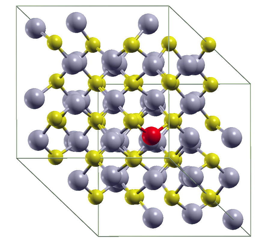
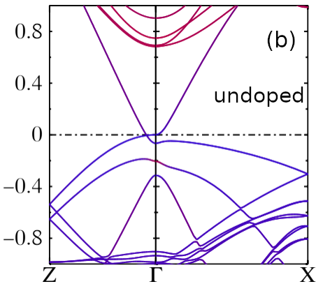
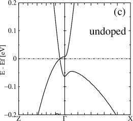
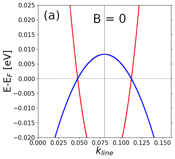
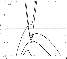
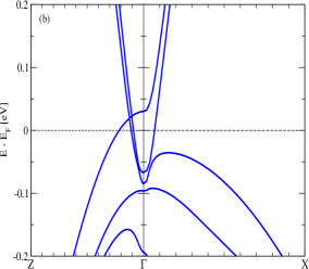
Before exploring the effects of Mn doping, we verify the known Cd3As2 band structure using both DFT and QS. Our DFT calculations (not shown) agree with previously reported band-structures Wang et al. (2013); Ali et al. (2014); Mosca Conte et al. (2017); Crassee et al. (2018); Yue et al. (2019); Kulatov et al. (2021); Brooks et al. (2023). Figure 1 shows our QS calculated band structures. Panels (b) and (c) in Fig.1 show the QS bands for undoped Cd3As2. Two Dirac points (i.e. crossing of 4 degenerate bands of mostly As character) are found at along the line, they are located at with , a slightly smaller value than those based on DFT calculations Wang et al. (2013); Ali et al. (2014); Mosca Conte et al. (2017); Yue et al. (2019).
The band velocity around the -point and around the Dirac points are given in Table 1 for pristine Cd3As2. The QS calculations provide, for at least one branch of the Dirac crossing bands, a velocity of [m/s], in agreement with values found in the literature Jeon et al. (2014); Liang et al. (2015); Nelson et al. (2023). By contrast, the band velocity is severely underestimated in DFT. This is to be expected because of the local potential DFT generates. DFT underestimates bandgaps in semiconductors Maksimov et al. (1989) and the Fermi velocity at the Dirac point in graphene van Schilfgaarde and Katsnelson (2011). A local LDA potential in the auxiliary DFT Hamiltonian results in underestimates of the bandgap, as clearly shown for a few semiconductors in Ref Grüning et al. (2006).
Shortcomings in the LDA and GGA are also reflected in the location of the Cd 5 states: in QSGW they are higher in energy than in DFT. When these states are too low, they may repel the As 4 states and contribute to the underestimate of the Fermi velocity. Also admix too much of Cd into the states in the vicinity of the Dirac point. Furthermore, the band inversion mechanism leading to the crossing at along the lines involves a parabolic and an inverted parabolic bands with mostly As 4 character. The effective mass of electron-like band is smaller than the effective mass of hole-like band, therefore around the Dirac point, one branch (annoted in Table 1) of the crossing bands is associated with a larger velocity than the other branch (annoted in Table 1).
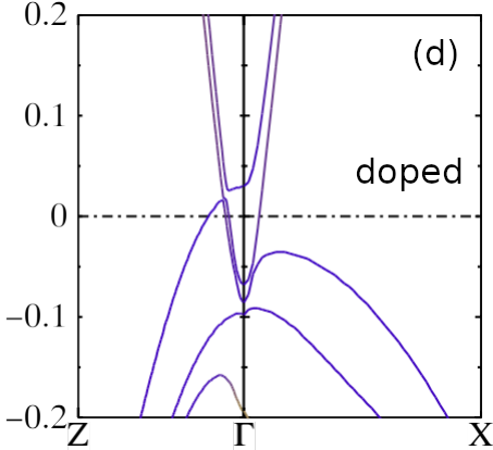
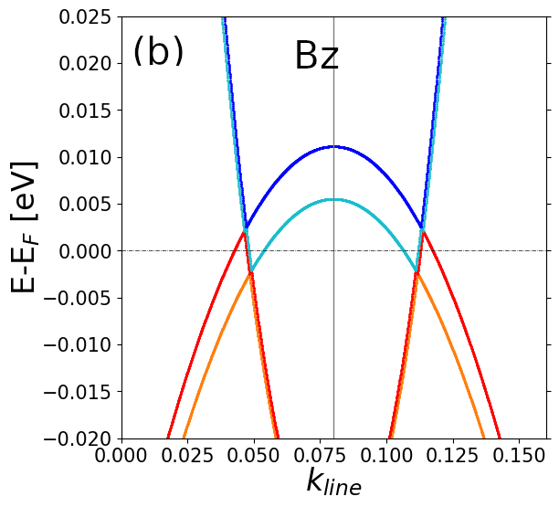
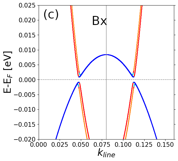
We now turn to the case of Cd3As2 doped by magnetic impurities. We consider that, for the Mn-doped system, one Cd atom in the unit cell is replaced by Mn, i.e. corresponding to a doping of 1/48 2 %. The band structure of the Mn-doped Cd3As2 is substantially different from the undoped system, see panel (d) in Figure 1. Bands are split by a Zeeman-like effect owing to the polarization of the As 4 states induced by the magnetic Mn impurity.
The Dirac point disappears from the symmetry protected -space line. Gapped bands occur around meV close to the point on the -path.
The majority(minority) Mn states consists of occupied (empty) states, centered at eV ( eV) respectively. They make the system ferromagnetic with a net moment of 5.0 . The Mn local moment in the Mn augmentation sphere is found to be 4.4 , the remaining 0.6 decaying away from the Mn. According to the Stoner picture, we should expect the energy splitting to be , where is the Stoner parameter and the local moment. As a rule of thumb, eV for 3 transition metals and would lead to eV. Thus the Stoner splitting is qualitatively correct, though it overestimates slightly the actual splitting. Both and are very localized, each with a bandwidth of eV. The dispersion establishes that the Mn band hybridizes to some extent with the Cd and As (the Mn-Mn separation is 12.6 , too large for direct coupling) and induces a small local moment on those sites. Two of the four As nearest neighbors to Mn acquire a moment of about 0.025 . For comparison, the Mn local moment in LDA is calculated to be 3.9 and the and band centers fall at approximately eV and ( eV), respectively. The splitting is small enough that states near have non-negligible Mn character. This shows only that the LDA does not provide an adequate description of the magnetic electronic structure.
As previously mentioned, the magnetic field coming from polarized Mn levels has a sharp local (in space) structure, somewhat different from what is expected from a macroscopic applied field. However, it is interesting to see to which extent this field acts in a similar manner as an applied external field.
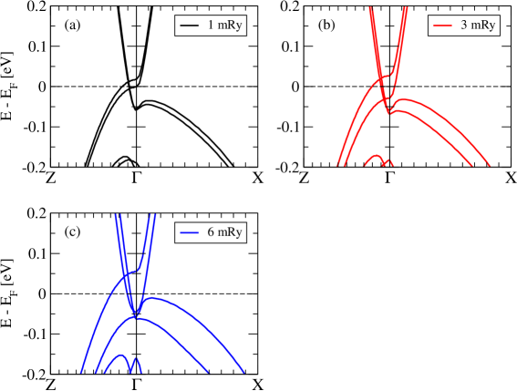
In order to get more insight into the band structure of Mn-doped Cd3As2, we consider next how the band structure of pristine Cd3As2 is modified by the presence of an applied external magnetic field (the latter emulating the presence of the Mn magnetic impurity).
Figure 2 shows the QS band structure of pristine Cd3As2 obtained in the presence of an external applied magnetic field oriented in the -direction. Upon application of the magnetic fields, bands are split due to the Zeeman effect, as expected. A large external field, as large as 6 mRy (72.2 meV or 1249.1 Tesla), generated a Zeeman band splitting similar to what is obtained for the Mn-doped Cd3As2 system. For that field value, the band structure of pristine Cd3As2 bears some strong resemblance with the bands of the Mn-doped crystal; although missing the apparent gapped band around meV seen in the Mn-doped case (comparing Figures 1(d) and 2(c) ).
II.2 Model Hamiltonian: electronic structure and external magnetic field effects
From ab-initio calculations, we have seen that an applied field to the undoped Cd3As2 can generate similar bands to the Mn-doped Cd3As2 system. The next question to solve is what happens to the Dirac points in the presence of Mn-doping and/or of the applied magnetic field?
To answer this question, we turn to a simpler model to describe the band structure of Cd3As2. Using such a model allows us to explore the -space bands more easily and to consider any arbitrary magnitude and orientation of the magnetic field. We consider a model consisting of four orbitals () and two spins for each orbital, and including a spin-orbit coupling term as described in Ref Wang et al. (2013). Furthermore, we add a Zeeman-like term where the magnetic field couples to the spin Pauli matrices . The Hamiltonian (of size ) is a function of three components of the crystal momentum , and is fully described in Appendix B. After diagonalization for each , the eigenvalues are used to build the corresponding band structure and additional physical quantities as detailed below. Such a model provides us with a quicker way to analyze how the Dirac points are displaced and/or split in -space due to the application of the magnetic field.
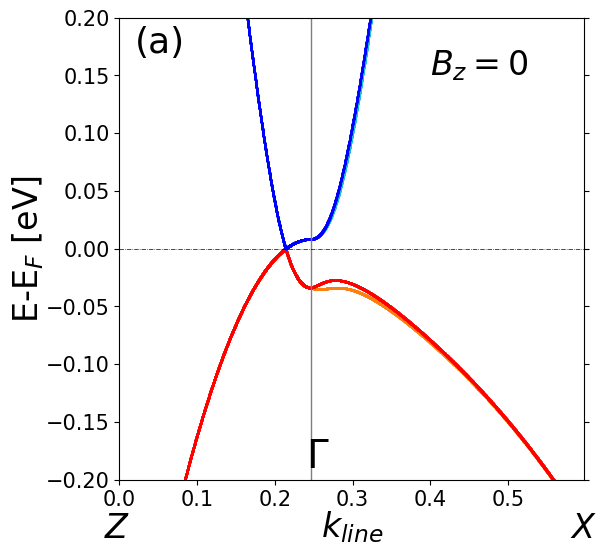
Figure 3 shows the band structure obtained from the Hamiltonian. In the absence of a magnetic field, the model provides a fairly good representation of the QS bands as can be seen by comparing Fig. 3(a) with the QS bands Fig. 1(c). With the model, we obtain a Dirac point at , very close to the QS calculations.
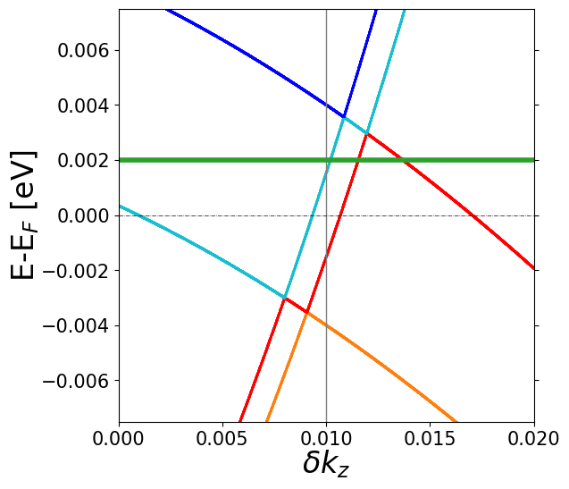
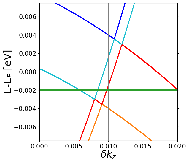
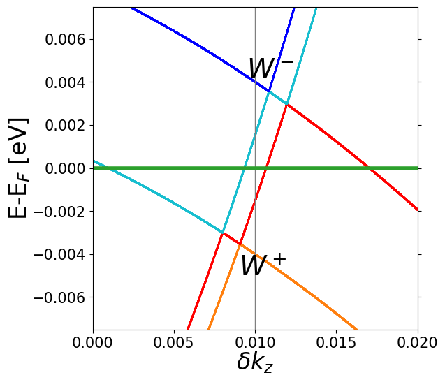
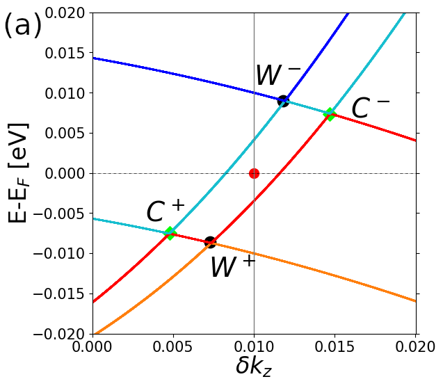
Upon application of a magnetic field in the -direction, the Dirac point is split into individual Weyl points Baidya and Vanderbilt (2020) displaced away from and shifted symmetrically up and down in energy around as shown in Figure 3(c). There are actually four band crossings, two above and two below. Two corresponding to a pair of “conventional” Weyl points (Chern number ) labelled in Fig. 9, and two labelled . Ref Baidya and Vanderbilt (2020) concluded that the crossing points are ”Weyl” points with Chern number 2. Our calculations align with Ref Baidya and Vanderbilt (2020) regarding the points, but we do not find pronounced Berry curvature around the points. This is discussed further in Appendix D.
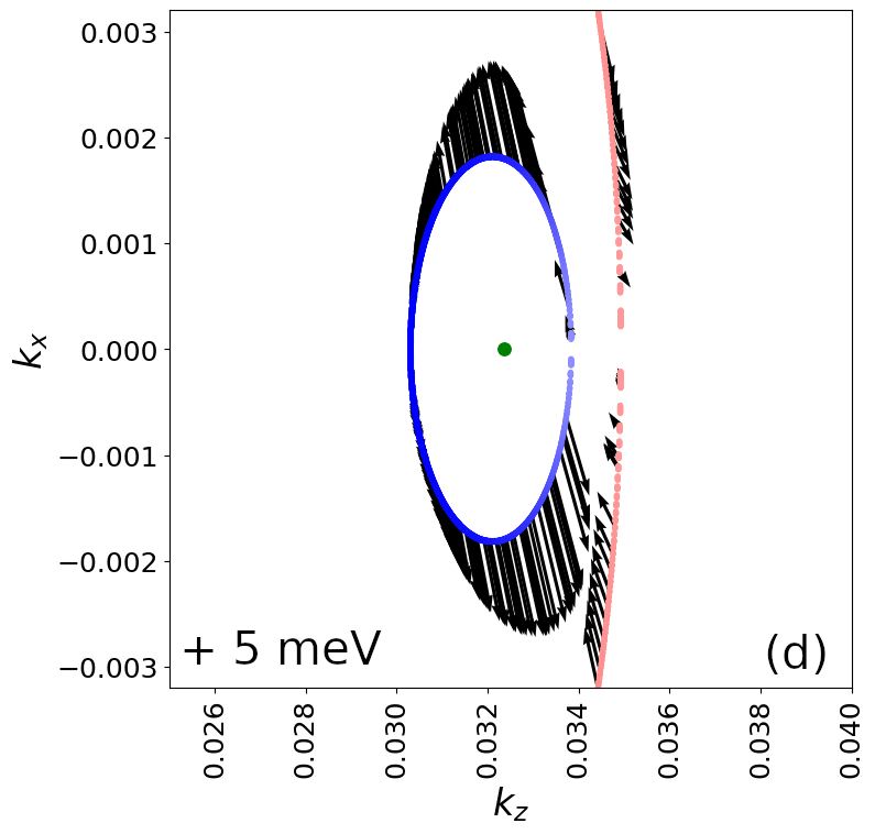
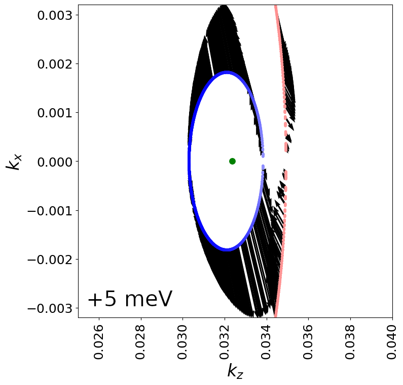
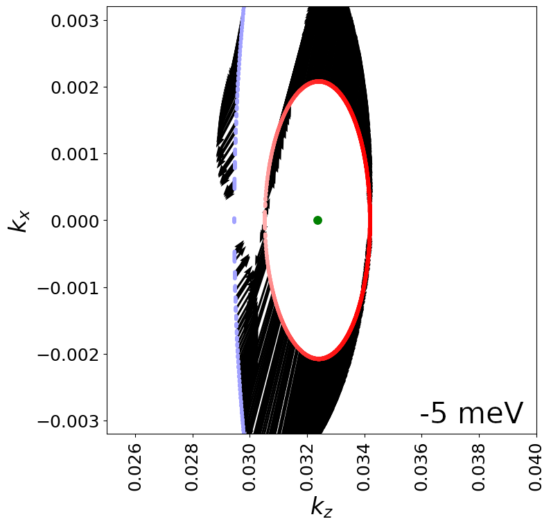
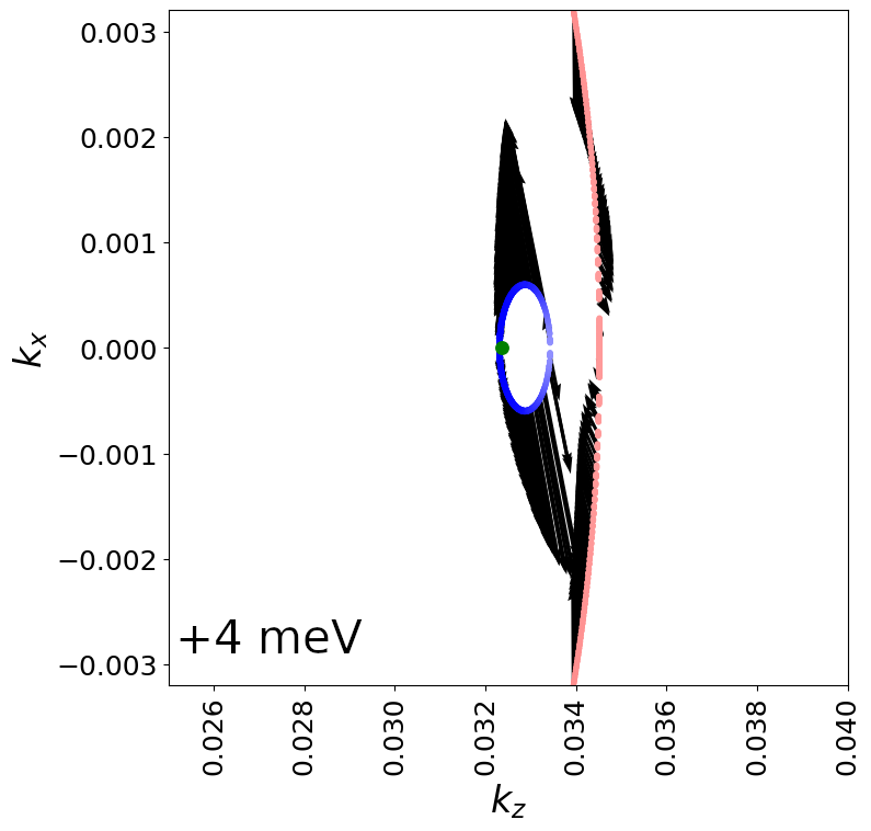
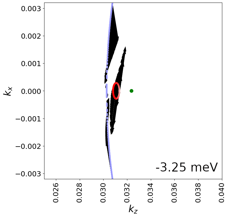
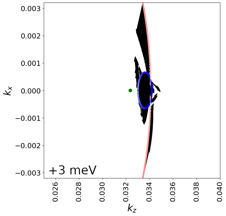
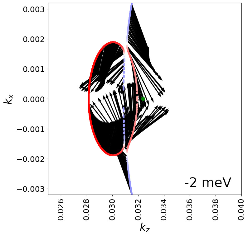
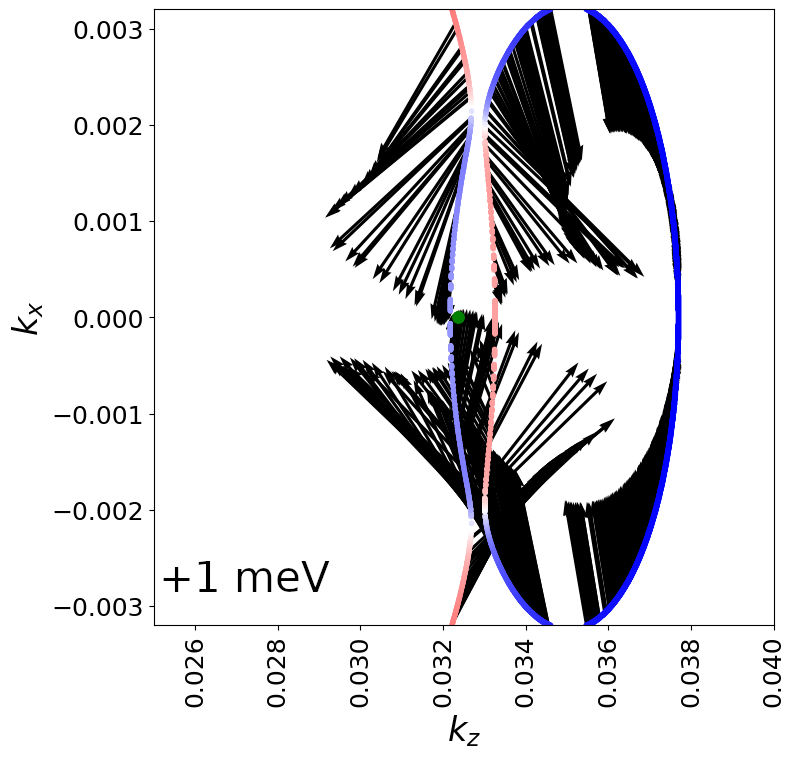
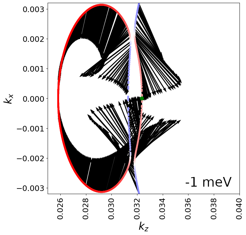
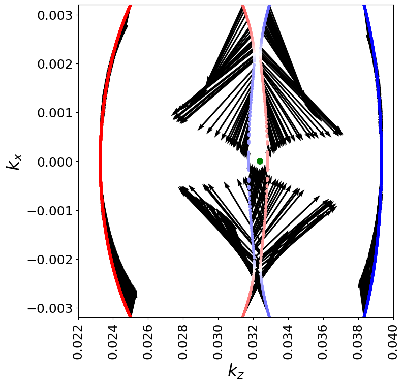
The identification of the Weyl bands and crossings can be made clearly by considering the bands spin texture. The spin components () are calculated from the expectation value of the spin Pauli matrices using the eigenstates of at each point. In Appendix D, we provide a full analysis of the spin texture of the different bands and for different constant energies ranging from meV to meV. Our analysis clearly identify the position of the Weyl points with opposite chirality. Figure 3(d) shows the two-dimensional constant-energy band structure, in the plane for a constant energy meV. The blue ellipse corresponds to a slice in the Weyl “cone” at , located around the original Dirac point (green dot in Fig. 3(d)). As discussed in the previous section, the bands around the Dirac points are anisotropic, i.e. they disperse with different velocities for different orientation. Hence a constant energy slice in the Weyl “cone” has the shape of an ellipse, instead of a circle (were the velocity of the Weyl cone to be isotropic).
For meV, the constant energy ellipse has the spin component oriented in one direction (opposite to the applied magnetic field) and anisotropic spin vectors oriented outwards the ellipse in the plane. The outer (red) band () shows a spin component with the opposite direction and a different kind of spin texture. As detailed in Appendix D, the outer band corresponds to the second Weyl “cone” located below around the original Dirac point.
Realistic band structure for real materials contains richer information in contrast to simpler band models considering only linear -dispersion for the Weyl cones. The former may lead to transport properties which differ from those calculated from simpler bands (considering the change of velocity, spin texture with respect to change of Fermi enery or temperature).
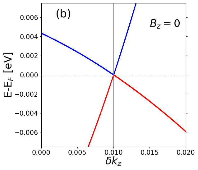
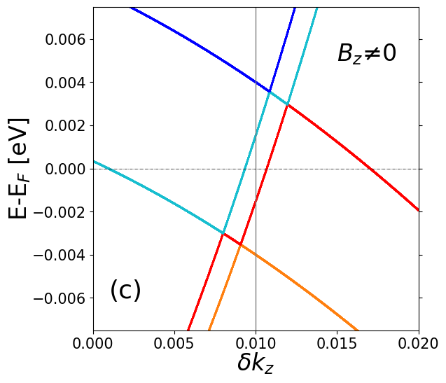
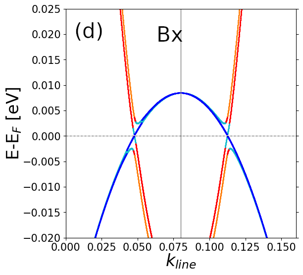
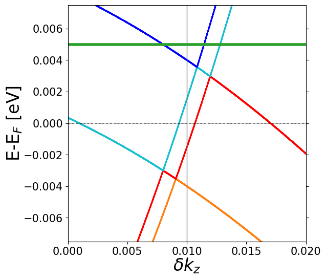
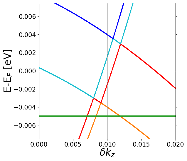
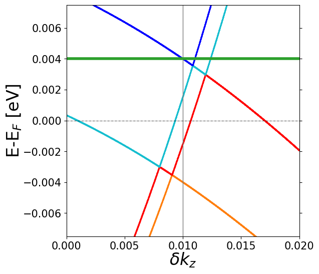
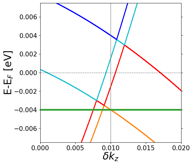
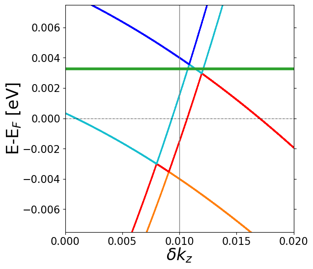
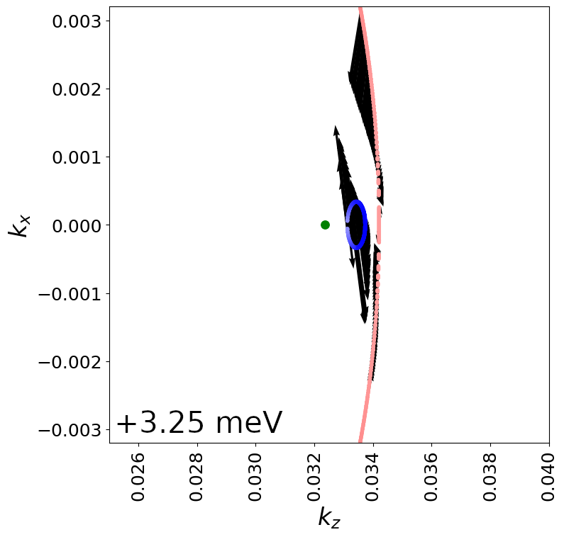
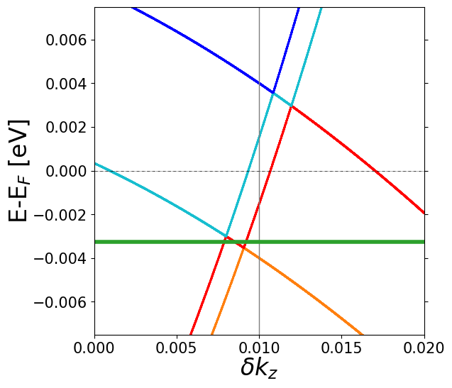
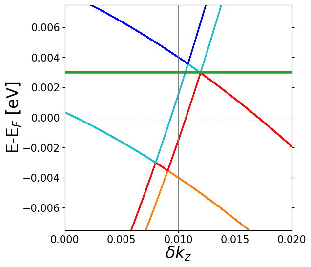
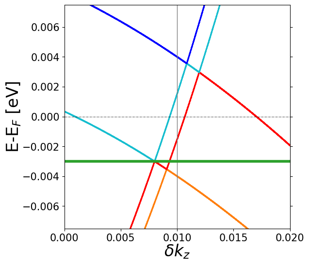
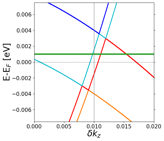
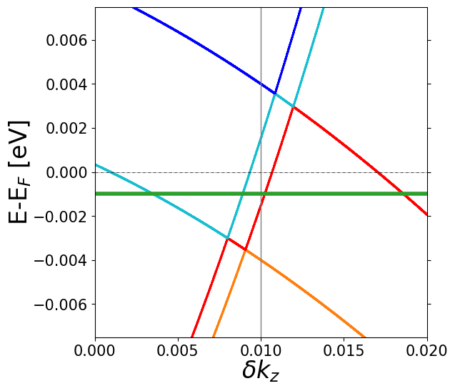
So far we have considered the case of a magnetic field applied in the -direction. It is crucial to know how the Dirac points are affected by a changing orientation of the field. Figure 4 compares how the Weyl points evolve from the Dirac points for fields along the and direction. For , bands drawn along the line, show that the Weyl points split in both and energy, as shown in Figure 3. The separation between Weyl points is parallel to . When , a gap appears on this same line; however, the Dirac point splits into two Weyl points at . Fig. 4(c) depicts bands for the same excursion in but offset by a fixed . In general the connecting vector between Weyl points is parallel to . However, the perturbation under a field causes no energy splitting of the Weyl points, unlike the case.
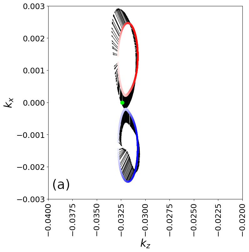
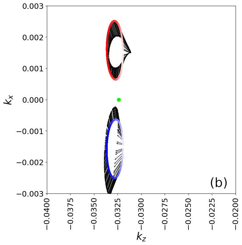
Figure 5 shows constant-energy band in the two-dimensional plane around the pair of Weyl points located at , moved along the -direction of the field, in -space. The spin texture is also represented for the three spin components . The opposite chirality between the two Weyl points is clearly seen, as well as the change of sign of the spin texture for energy above and below the Weyl crossing points.
II.3 Reconciling the doped and undoped Cd3As2 cases
Our electronic structure calculations with the model Hamiltonian have shown that the application of an external magnetic field splits the Dirac point into a pair at Weyl points of opposite chirality. They are displaced symmetrically around , possibly with a small energy shift.
Such a behaviour should also, in principle, hold for the band structure of the realistic cases of doped and undoped Cd3As2. In Mn-doped Cd3As2, the gap around close to is only apparent: the bands do still cross but at a displaced point. Indeed, by plotting the QS band structure of Mn-doped Cd3As2 along the -path slightly shifted in the direction, one recovers a closed gap as shown in Figure 6. This is where one of the Weyl point has been moved by the field generated by the magnetic impurity.
This implies that the local magnetic field due to the Mn impurity is slightly canted away from the -direction. This small deviation of the field towards the -direction is most probably related to spin-orbit coupling in the QS Hamiltonian of Mn-doped Cd3As2 generating a slight canting away from the -axis.
Thus, the magnetic impurity does not open a gap in the band structure and one can reasonably well emulate the “exact” band structure of Mn-doped Cd3As2 from the band structure of pristine Cd3As2 by applying an appropriate external magnetic field. This is clearly seen by comparing Figure 6(b) with Figure 2(c).
These results also lead us to believe that one can use the model Hamiltonian, complemented with the Zeeman term for an applied field, to calculate physical properties measured on Mn-doped Cd3As2 sample.
II.4 Conductivity and orientation of the magnetic field
The transport properties of TSMs are intimately related to their band structures. We have seen how the band structure of Cd3As2 is modified by magnetic impurity doping and/or by an applied magnetic field. We now turn to studying some effects of a magnetic field on the conductivity of bulk Cd3As2.
In Weyl TSM, an anomalous Hall DC conductivity is observed with a value lying between zero (conductivity of insulators) and one quantum of conductance for topological insulator Burkov and Balents (2011); Panfilov et al. (2014); Armitage et al. (2018). The DC Hall conductivity, governed by Berry phase, is proportional to the separation in -space of two Weyl points which itself may depend on the applied magnetic field.
Magnetotransport of bulk TSM involve additional features not included here (especially the role Landau levels play) and will be discussed elsewhere. In the following we focus on how an applied field affects the symmetry of the dynamical conductivity tensor.
From the eigenstates of and from the velocity matrices , we can calculate the conductivity tensor () within linear response theory Bastin et al. (1971); Crépieux and Bruno (2001); Bruus and Flensberg (2004); Vasko and Raichev (2005); Morimoto and Aoki (2012); Gradhand et al. (2012). Detail of the calculations are provided in Appendix C. In the DC regime, the definition of from the Berry curvature Gradhand et al. (2012) implies that conductivity tensor is anti-symmetric, i.e. for . This is due to the property of the cross product of the current operator matrix elements entering the definition of the Berry curvature Gradhand et al. (2012).
In the AC regime (), the anti-symmetry of the conductivity tensor is not obvious, as shown in Appendix C. The symmetry of the conductivity tensor will depend on the intrinsic symmetry of the eigenstates, and therefore on the orientation of the magnetic field. In the following, we show the symmetry of the off-diagonal components () for arbitrary orientation of the external magnetic field.
As a first step, we have checked that our calculations satisfy the Onsager relationships, as expected, i.e. (and likewise for the components with an applied field, and for the components with an applied ). Different symmetry relationships may hold for arbitrary orientations of the applied field.
The results of our calculations with different field orientations are summarised in Figure 7. For an applied field along the high symmetry Cartesian directions , only the (Hall) conductivity in the plane perpendicular to the field is non-zero, as should be expected. For example, with , only the components are non-zero; and similarly for the components () components with an applied (). These pairs of components are anti-symmetric, i.e. . similarly to the DC case.
For other orientations of the field, more than one pair of ( components have non-zero conductivity values. This comes essentially from the symmetry of the rotation of the frame-axis and the fact that only the “perpendicular to the field” (non-diagonal) components of the conductivity are non-zero. For field orientation along some symmetry lines [110], [101], [011], we find that there is always at least one pair of components which provide anti-symmetry. This is a very interesting outcome for the optical properties of TSM Kotov and Lozovik (2016); Hofmann and Das Sarma (2016); Kotov and Lozovik (2018). Indeed, the anti-symmetry of the (dynamical) conductivity tensor is a central key in order to obtain non-reciprocity effects of light Kotov and Lozovik (2018) and thermal radiation Zhao et al. (2020) in Weyl TSMs.
Our results imply that the local field, whatever its origin, does not need to be strictly oriented along high symmetry Cartesian axis to realize antisymmetry of the optical conductivity tensor, and therefore in order to obtain non-reciprocal effects in Weyl TSMs. .
III Conclusion
We have studied electronic structure of bulk Cd3As2 by using QS electronic structure calculations and a model Hamiltonian. We have shown that substitutional doping by Mn impurities, in the small doping regime, induce a topological phase transition, i.e. the original Dirac points in pristine Cd3As2 split into individual Weyl points. We have demonstrated that the electronic structure of Mn-doped Cd3As2 can be fairly well reproduced by the electronic structure of pristine Cd3As2 with an appropriate external magnetic field. This result highlights opportunities for unique device functionality based on band structure tuning which is not found in conventional magnetic Weyl TSM. Using a model Hamiltonian, in the presence of an applied magnetic field, we have studied the conductivity of bulk Cd3As2 for different orientations of the applied field and shown the symmetry properties of the conductivity tensor.
From an experimental standpoint, substitutional doping with Mn must first be demonstrated in Cd3As2 Rice et al. (2025), followed by verification of changes in the bandstructure and properties.
At dilute doping, spins will be disordered; causing the net field to be small. However an applied field may act to align the Mn spins, greatly enhancing the spin susceptibility relative to pristine Cd3As2. At higher doping the Mn can interact, and affect the spin ordering and modify the effective field. Also we considered substitutional doping only. The interstitial Mn(I) may act differently from the substitutional Mn(s), especially as Mn(I) will dope the system. Also Mn(I)-Mn(s) interactions can be very different from Mn(s)-Mn(s) interaction, which can affect the thermodynamic distribution of dopants and the total spin.
Acknowledgements.
This work was authored in part by the National Renewable Energy Laboratory for the U.S. Department of Energy (DOE) under Contract No. DE-AC36-08GO28308. Funding was provided by the U.S. Department of Energy (DOE), Office of Science, Basic Energy Sciences, Physical Behavior of Materials Program as part of the “Disorder in Topological Semimetals” project. The views expressed in the article do not necessarily represent the views of the DOE or the U.S. Government. The U.S. Government retains and the publisher, by accepting the article for publication, acknowledges that the U.S. Government retains a nonexclusive, paid-up, irrevocable, worldwide license to publish or reproduce the published form of this work, or allow others to do so, for U.S. Government purposes. We acknowledge the use of the National Energy Research Scientific Computing Center, under Contract No. DE-AC02-05CH11231 using NERSC award BES-ERCAP0021783 and we also acknowledge that a portion of the research was performed using computational resources sponsored by the Department of Energy’s Office of Energy Efficiency and Renewable Energy and located at the National Renewable Energy Laboratory. HN acknowledges financial support from NREL via a subcontract agreement between KCL and NREL.Appendix A Questaal calculations
For electronic structure calculations, we use the Quasiparticle Self-Consistent approximation Faleev et al. (2004); van Schilfgaarde et al. (2006); Kotani et al. (2007). Quasiparticlization of the self-energy yields a static one-particle band similar in form to Hartree–Fock or DFT, but its fidelity is high because the potential is constructed so that energy bands physically correspond to excitation energies. This is because the QS self-consistency condition causes the poles of the noninteracting Green’s function to coincide with the interacting one. DFT energy bands, by contrast, have no physical meaning even though they are widely interpreted as excitation energies. See Refs. Pashov et al. (2020); que for further details on the Questaal code and implementation of QS.
We use a primitive unit cell, consisting of 80 atoms (48 atoms of Cd and 32 of As), with broken inversion symmetry. The lattice cell vectors are for the pristine Cd3As2 system where and . For the Mn-doped case, one Cd atom is exchanged with one atom of Mn, i.e. corresponding to a doping of 1/48 2 % (an equivalent supercell built from the vectors is used).
For the DFT calculations, a -point grid of was used for the DFT calculations. A smaller grid of was used for QS calculations. The self-consistency of the DFT/QS calculations is achieved when the RMS change in output-input self-energy and charge density were both converged to about . For QS calculations, all the states are used in the present case (5664 states in the total system, with 4612 of them unoccupied). Questaal’s basis set is tailored to the potential Pashov et al. (2020), so that quasiparticle levels converge much more rapidly with the number of states than what occurs for a plane wave basis. Band structure calculations, in the presence of the self-energy, were performed with a denser k-point grid mesh.
Appendix B The Hamiltonian
The model Hamiltonian Wang et al. (2013); Smith et al. (2024) is build on 4 bands ( and orbitals) and 2 spins, including spin-orbit coupling (SOC) and a Zeeman-like term:
| (1) |
where is the identity in the spin space.
For a given spin, the Hamiltonian , in the basis of the and orbitals, is given by
| (2) |
Cubic symmetry is broken by using: and . The parameter is introduced to break the inversion symmetry Wang et al. (2013).
The SOC term is
| (3) |
where is the vector of Pauli matrices , are (44) matrices in the orbital basis, and with
For the orbital, the angular momentum is zero. Hence we have
| (4) |
In the basis of the orbitals, the angular momentum is given by
| (5) |
The Zeeman term is
| (6) |
with .
In the orbital basis, we take
| (7) |
and apply the field “uniformly” on the orbitals only, i.e. and .
Note that calculations with do not change significantly the electronic structure around the Dirac point; and not affect the results of the symmetry of the conductivity tensor upon the direction of the applied field.
The value of the parameters are taken from Ref. [Wang et al., 2013] with a small modification of the SO coupling constant (here we take 0.155 eV) to make the Dirac points align with the Fermi level within a range of eV.
Appendix C Linear response conductivity
The (dynamical) electrical conductivity is obtained from linear response theory and given by Bastin et al. (1971); Bruus and Flensberg (2004); Vasko and Raichev (2005)
| (8) |
where is the so-called gauge term proportional to Bastin et al. (1971); Bruus and Flensberg (2004); Vasko and Raichev (2005) and the Cartesian coordinates. The current-current correlation function is
| (9) |
where is the Fermi-Dirac distribution function, the current operators, and are the Green’s functions (with ) and .
Using a compact notation for the eigenstates of , and , one recovers the usual expression for the dynamical conductivity (with ) Bastin et al. (1971); Crépieux and Bruno (2001); Bruus and Flensberg (2004); Vasko and Raichev (2005); Morimoto and Aoki (2012); Gradhand et al. (2012)
| (10) |
The matrix elements of the -component of the current operator are obtained, in the -space, from the matrix elements . Analytical expressions for are readily obtained from Eq.(2).
Also, note that by swapping the indices, one obtains an expression for which is clearly different from Eq. 10:
| (11) |
Therefore, unless there is a very specific symmetry in the Hamiltonian, reflected in the spectrum and the eigenstates , one cannot easily conclude if the conductivity tensor is symmetric, or anti-symmetric. Also note that, and being Hermitian, is not enough to explain the (anti)symmetry.
Finally, when performing actual calculations, the sums implicitly include the -dependence of the eigenstates, i.e.
| (12) |
Numerical calculations were performed for a regular cubic -point grid, centered on the point, ranging from -0.08 to 0.08 in the three Cartesian directions. A mesh of () was used, i.e. more than 44 millions -points in order to fully capture the contributions of the Weyl points Gradhand et al. (2012).
Appendix D Indentification of the Weyl points
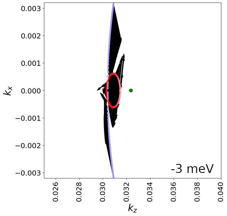
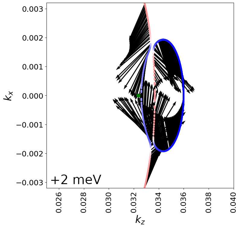
In this appendix, we show in detail the spin texture of the bands around the Dirac point at ) in Figure 3. We calculate the spin components from expectation value of the Pauli matrices using the eigenstates of at each point.
In Figure 8, the 2D maps represent the spin vectors in the plane as black arrows. The color coding of the 2D constant energy contours corresponds to the spin component: blue for minority spin , red for majority spin , and white for .
Due to the field applied in the -direction, the Dirac point is split into individual Weyl points Baidya and Vanderbilt (2020) located at . The constant energy slices in the Weyl “cones” have elliptic shapes because of the anisotropy of the band velocity in -space. The Weyl points are shifted in energy from by the Zeeman effect, down by for the Weyl point with majority spin along the -direction , and shifted up by for the Weyl point with minority spin directed in the opposite direction of the applied field (see red and blue ellipses in Fig. 8 respectively).
Let us first focus on the Weyl point above . For energies above the Weyl point (i.e. ), the spin vectors are directed outwards the blue ellipses, while for energies below the Weyl point the spin vectors are directed inwards.
The other Weyl point , located below , has the opposite chirality as expected. That is for energies above the Weyl point, the spin vectors are directed inwards the red ellipses, while for energies below the Weyl point the spin vectors are directed outwards.
Note that the constant energy slices of a given Weyl “cone”, i.e. blue or red ellipses for (with Chern number according to Ref Baidya and Vanderbilt (2020)), are accompanied with another band (red or blue respectively) with opposite spin direction which originates from the other Weyl “cone” (at opposite energy).
The two other crossings, labelled in Figure 9(a), have been identified as other Weyl points associated with higher Chern number in Ref Baidya and Vanderbilt (2020). Our results reflect a different picture for the points, and the difference can be important because of the central role spin texture plays in transport properties of TSM. For example, the (anomalous) Hall conductivity is given in terms of the Berry curvature Gradhand et al. (2012); Baidya and Vanderbilt (2020).
From the eigenstates of , we can calculate the components of the Berry curvature for a given eigenstate as follows:
| (13) |
with and .
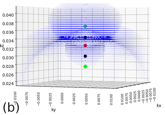
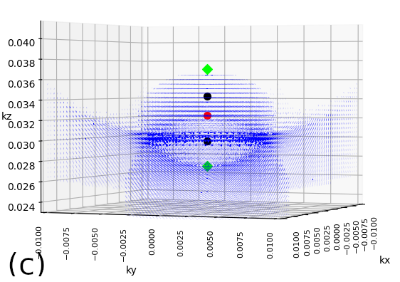
Figure 9 shows two 3D maps, in the -space, of the Berry curvature vectors as blue arrows. We have intentionally displayed the arrows as short arrows in order to avoid strong overlap of the different vectors at different -points which may lead to confusion. The quantities come from the summation of over an chosen energy window . We have choosen energy windows around the pairs to check which of the crossing points provide the more Berry curvature. In Fig. 9(b), the summation is performed for the energy window around the pair of and crossing points; in Fig. 9(c) for the energy window around the pair of and crossings. The line of symbols, at , represent the sequence of points along , with the Dirac point at . For both integration windows, one can clearly see a large contribution of Berry curvature around the Weyl points (black dots) in comparison to a smaller Berry curvature around the crossing points (green diamonds). This tends to indicate that, amongst the four band crossings , the Weyl points will be playing a more important role in the transport properties based on Berry curvatures.
We have not attempted to analyze why Ref Baidya and Vanderbilt (2020) and this work arrive at different conclusions about the points. The discrepancy can probably be traced to a difference in the construction of the k.p hamiltonians.
References
- Armitage et al. (2018) N. P. Armitage, E. J. Mele, and A. Vishwanath, Weyl and Dirac semimetals in three-dimensional solids, Rev. Mod. Phys. 90, 015001 (2018).
- Li et al. (2020) J. Li, Z. Zhang, C. Wang, H. Huang, B.-L. Gu, and W. Duan, Topological semimetals from the perspective of first-principles calculations, Journal of Applied Physics 128, 191101 (2020).
- Liang et al. (2015) T. Liang, Q. Gibson, M. N. Ali, M. Liu, R. J. Cava, and N. P. Ong, Ultrahigh mobility and giant magnetoresistance in the Dirac semimetal Cd3As2, Nature Materials 14, 280 (2015).
- Wang et al. (2020) A.-Q. Wang, X.-G. Ye, D.-P. Yu, and Z.-M. Liao, Topological Semimetal Nanostructures: From Properties to Topotronics, ACS Nano 14, 3755 (2020).
- He et al. (2022) Q. L. He, T. L. Hughes, N. P. Armitage, Y. Tokura, and K. L. Wang, Topological spintronics and magnetoelectronics, Nature Materials 21, 15 (2022).
- Bernevig et al. (2022) B. A. Bernevig, C. Felser, and H. Beidenkopf, Progress and prospects in magnetic topological materials, Nature 603, 41 (2022).
- Lee et al. (2022) W. J. Lee, Y. A. Salawu, H.-J. Kim, C. W. Jang, S. Kim, T. Ratcliff, R. G. Elliman, Z. Yue, X. Wang, S.-E. Lee, M.-H. Jung, J.-S. Rhyee, and S.-H. Choi, Possible permanent Dirac- to Weyl-semimetal phase transition by ion implantation, NPG Asia Materials 14, 31 (2022).
- Wang et al. (2019) L.-L. Wang, N. H. Jo, B. Kuthanazhi, Y. Wu, R. J. McQueeney, A. Kaminski, and P. C. Canfield, Single pair of Weyl fermions in the half-metallic semimetal EuCd2As2, Phys. Rev. B 99, 245147 (2019).
- Ma et al. (2019) J.-Z. Ma, S. M. Nie, C. J. Yi, J. Jandke, T. Shang, M. Y. Yao, M. Naamneh, L. Q. Yan, Y. Sun, A. Chikina, V. N. Strocov, M. Medarde, M. Song, Y.-M. Xiong, G. Xu, W. Wulfhekel, J. Mesot, M. Reticcioli, C. Franchini, C. Mudry, M. Müller, Y. G. Shi, T. Qian, H. Ding, and M. Shi, Spin fluctuation induced Weyl semimetal state in the paramagnetic phase of EuCd2As2, Science Advances 5, 4718 (2019).
- Santos-Cottin et al. (2023) D. Santos-Cottin, I. Mohelský, J. Wyzula, F. Le Mardelé, I. Kapon, S. Nasrallah, N. Barišić, I. Živković, J. R. Soh, F. Guo, K. Rigaux, M. Puppin, J. H. Dil, B. Gudac, Z. Rukelj, M. Novak, A. B. Kuzmenko, C. C. Homes, T. Dietl, M. Orlita, and A. Akrap, EuCd2As2: A Magnetic Semiconductor, Phys. Rev. Lett. 131, 186704 (2023).
- Shi et al. (2024) Y. Shi, Z. Liu, L. A. Burnett, S. Lee, C. Hu, Q. Jiang, J. Cai, X. Xu, M. Li, C.-C. Chen, and J.-H. Chu, Absence of weyl nodes in EuCd2As2 revealed by the carrier density dependence of the anomalous Hall effect, Phys. Rev. B 109, 125202 (2024).
- Nishihaya et al. (2024) S. Nishihaya, A. Nakamura, M. Ohno, M. Kriener, Y. Watanabe, M. Kawasaki, and M. Uchida, Intrinsic insulating transport characteristics in low-carrier density EuCd2As2 films, Applied Physics Letters 124, 023103 (2024).
- Rice et al. (2025) A. D. Rice, I. A. Leahy, H. Ness, M. van Schilfgaarde, and K. Alberi, unknown, (unpublished) (2025).
- Liu et al. (2014) Z. K. Liu, J. Jiang, B. Zhou, Z. J. Wang, Y. Zhang, H. M. Weng, D. Prabhakaran, S.-K. Mo, H. Peng, P. Dudin, T. Kim, M. Hoesch, Z. Fang, X. Dai, Z. X. Shen, D. L. Feng, Z. Hussain, and Y. L. Chen, A stable three-dimensional topological Dirac semimetal Cd3As2, Nature Materials 13, 677 (2014).
- (15) Questaal code website, https://www.questaal.org.
- Pashov et al. (2020) D. Pashov, S. Acharya, W. R. Lambrecht, J. Jackson, K. D. Belashchenko, A. Chantis, F. Jamet, and M. van Schilfgaarde, Questaal: A package of electronic structure methods based on the linear muffin-tin orbital technique, Comput. Phys. Commun 249, 107065 (2020).
- Faleev et al. (2004) S. V. Faleev, M. van Schilfgaarde, and T. Kotani, All-electron self-consistent approximation: Application to Si, Mno, and NiO, Phys. Rev. Lett. 93, 126406 (2004).
- van Schilfgaarde et al. (2006) M. van Schilfgaarde, T. Kotani, and S. Faleev, Quasiparticle Self-Consistent Theory, Phys. Rev. Lett. 96, 226402 (2006).
- Kotani et al. (2007) T. Kotani, M. van Schilfgaarde, and S. V. Faleev, Quasiparticle self-consistent method: A basis for the independent-particle approximation, Phys. Rev. B 76, 165106 (2007).
- Wang et al. (2013) Z. Wang, H. Weng, Q. Wu, X. Dai, and Z. Fang, Three-dimensional Dirac semimetal and quantum transport in Cd3As2, Phys. Rev. B 88, 125427 (2013).
- Ali et al. (2014) M. N. Ali, Q. Gibson, S. Jeon, B. B. Zhou, A. Yazdani, and R. J. Cava, The crystal and electronic structures of Cd3As2, the three-dimensional electronic analogue of graphene, Inorganic Chemistry 53, 4062 (2014).
- Mosca Conte et al. (2017) A. Mosca Conte, O. Pulci, and F. Bechstedt, Electronic and optical properties of topological semimetal Cd3As2, Scientific Reports 7, 45500 (2017).
- Crassee et al. (2018) I. Crassee, R. Sankar, W.-L. Lee, A. Akrap, and M. Orlita, 3D Dirac semimetal Cd3As2: A review of material properties, Phys. Rev. Mater. 2, 120302 (2018).
- Yue et al. (2019) S. Yue, H. T. Chorsi, M. Goyal, T. Schumann, R. Yang, T. Xu, B. Deng, S. Stemmer, J. A. Schuller, and B. Liao, Soft phonons and ultralow lattice thermal conductivity in the Dirac semimetal Cd3As2, Phys. Rev. Res. 1, 033101 (2019).
- Kulatov et al. (2021) E. Kulatov, Y. Uspenskii, L. Oveshnikov, A. Mekhiya, A. Davydov, A. Ril’, S. Marenkin, and B. Aronzon, Electronic, magnetic and magnetotransport properties of Mn-doped Dirac semimetal Cd3As2, Acta Materialia 219, 117249 (2021).
- Brooks et al. (2023) C. Brooks, M. van Schilfgaarde, D. Pashov, J. N. Nelson, K. Alberi, D. S. Dessau, and S. Lany, Band energy dependence of defect formation in the topological semimetal Cd3As2, Phys. Rev. B 107, 224110 (2023).
- Jeon et al. (2014) S. Jeon, B. B. Zhou, A. Gyenis, B. E. Feldman, I. Kimchi, A. C. Potter, Q. D. Gibson, R. J. Cava, A. Vishwanath, and A. Yazdani, Landau quantization and quasiparticle interference in the three-dimensional Dirac semimetal Cd3As2, Nature Materials 13, 851 (2014).
- Nelson et al. (2023) J. N. Nelson, I. A. Leahy, A. D. Rice, C. Brooks, G. Teeter, M. van Schilfgaarde, S. Lany, B. Fluegel, M. Lee, and K. Alberi, Direct link between disorder and magnetoresistance in topological semimetals, Phys. Rev. B 107, L220206 (2023).
- Maksimov et al. (1989) E. G. Maksimov, I. I. Maxin, S. Y. Savrasov, and Y. A. Uspenski, Excitation spectra of semiconductors and insulators: a density-functional approach to many-body theory, Journal of Physics: Condensed Matter 1, 2493 (1989).
- van Schilfgaarde and Katsnelson (2011) M. van Schilfgaarde and M. I. Katsnelson, First-principles theory of nonlocal screening in graphene, Phys. Rev. B 83, 081409 (2011).
- Grüning et al. (2006) M. Grüning, A. Marini, and A. Rubio, Density functionals from many-body perturbation theory: The band gap for semiconductors and insulators, J. Chem. Phys. 124, 154108 (2006).
- Baidya and Vanderbilt (2020) S. Baidya and D. Vanderbilt, First-principles theory of the Dirac semimetal Cd3As2 under Zeeman magnetic field, Phys. Rev. B 102, 165115 (2020).
- Burkov and Balents (2011) A. A. Burkov and L. Balents, Weyl semimetal in a topological insulator multilayer, Phys. Rev. Lett. 107, 127205 (2011).
- Panfilov et al. (2014) I. Panfilov, A. A. Burkov, and D. A. Pesin, Density response in Weyl metals, Phys. Rev. B 89, 245103 (2014).
- Bastin et al. (1971) A. Bastin, C. Lewiner, O. Betbeder-Matibet, and P. Nozieres, Quantum oscillations of the Hall effect of a Fermion gaz with random impurity scattering, J. Phys. Chem. Solids 32, 1811 (1971).
- Crépieux and Bruno (2001) A. Crépieux and P. Bruno, Theory of the anomalous Hall effect from the Kubo formula and the Dirac equation, Phys. Rev. B 64, 014416 (2001).
- Bruus and Flensberg (2004) H. Bruus and K. Flensberg, Many-Body Quantum Theory in Condensed Matter Physics: An Introduction (Oxford University Press, Oxford, 2004).
- Vasko and Raichev (2005) F. T. Vasko and O. E. Raichev, Quantum Kinetic Theory and Applications: Electrons, Photons, Phonons (Springer, New York, 2005).
- Morimoto and Aoki (2012) T. Morimoto and H. Aoki, Flow diagram of the longitudinal and Hall conductivities in ac regime in the disordered graphene quantum hall system, Journal of Physics: Conference Series 400, 042047 (2012).
- Gradhand et al. (2012) M. Gradhand, D. V. Fedorov, F. Pientka, P. Zahn, I. Mertig, and B. L. Györffy, First-principle calculations of the Berry curvature of Bloch states for charge and spin transport of electrons, Journal of Physics: Condensed Matter 24, 213202 (2012).
- Kotov and Lozovik (2016) O. V. Kotov and Y. E. Lozovik, Dielectric response and novel electromagnetic modes in three-dimensional Dirac semimetal films, Phys. Rev. B 93, 235417 (2016).
- Hofmann and Das Sarma (2016) J. Hofmann and S. Das Sarma, Surface plasmon polaritons in topological Weyl semimetals, Phys. Rev. B 93, 241402 (2016).
- Kotov and Lozovik (2018) O. V. Kotov and Y. E. Lozovik, Giant tunable nonreciprocity of light in Weyl semimetals, Phys. Rev. B 98, 195446 (2018).
- Zhao et al. (2020) B. Zhao, C. Guo, C. A. C. Garcia, P. Narang, and S. Fan, Axion-field-enabled nonreciprocal thermal radiation in Weyl semimetals, Nano Letters 20, 1923 (2020).
- Smith et al. (2024) M. Smith, V. L. Quito, A. A. Burkov, P. P. Orth, and I. Martin, Theory for Cd3As2 thin films in the presence of magnetic fields, Phys. Rev. B 109, 155136 (2024).