Max-Min Secrecy Rate and Secrecy Energy Efficiency Optimization for RIS-Aided VLC Systems: RSMA Versus NOMA
Abstract
Integrating visible light communication (VLC) with the reconfigurable intelligent surface (RIS) significantly enhances physical layer security by enabling precise directional signal control and dynamic adaptation to the communication environment. These capabilities strengthen the confidentiality and security of VLC systems. This paper presents a comprehensive study on the joint optimization of VLC access point (AP) power allocation, RIS association, and RIS elements orientation angles for secure VLC systems, while considering rate-splitting multiple access (RSMA) and power-domain non-orthogonal multiple access (NOMA) schemes. Specifically, two frameworks are proposed to maximize both the minimum secrecy rate (SR) and the minimum secrecy energy efficiency (SEE) by jointly optimizing power allocation, RIS association, and RIS elements orientation angles for both power-domain NOMA and RSMA-based VLC systems. The proposed frameworks consider random device orientation and guarantee the minimum user-rate requirement. The proposed optimization frameworks belong to the class of mixed integer nonlinear programming, which has no known feasible solution methodology to guarantee the optimal solution. Moreover, the increased degree of freedom and flexibility from the joint consideration of power control, RIS association and element orientation results in a large set of decision variables and constraints, which further complicates the optimization problem. To that end, we utilize a genetic algorithm-based solution method, which through its exploration and exploitation capabilities can obtain a good quality solution. Additionally, comprehensive simulations show that the RSMA scheme outperforms the power-domain NOMA scheme across both the SR and SEE metrics over various network parameters. Furthermore, useful insights on the impact of minimum user rate requirement, number of RIS elements, and maximum VLC AP transmit power on the minimum SR and SEE performances are provided.
Index Terms:
Visible light communications (VLC), physical layer security (PLS), reflecting intelligent surface (RIS), rate splitting multiple access (RSMA), non-orthogonal multiple access (NOMA), secrecy rate (SR), secrecy energy efficiency (SEE), Max-Min optimization.I Introduction
Visible light communications (VLC) is increasingly recognized as a vital technology for next-generation wireless communications, especially within sixth generation (6G) networks. In VLC, the visible light spectrum (- nm) is utilized for data transmission, offering several advantages over conventional radio frequency (RF) communications [1]. For instance, VLC provides a vastly larger unlicensed bandwidth, alleviating spectrum scarcity and supporting high data rates necessary for 6G applications like virtual reality (VR) and augmented reality (AR) [2]. Moreover, VLC systems are immune to electromagnetic interference, making them suitable for environments where RF interference is prevalent or RF communication is restricted. However, VLC faces challenges such as the line-of-sight (LoS) requirement, limited coverage area, and susceptibility to security threats due to its broadcasting nature. Some solutions, including advanced beam steering technologies, multi-hop communication strategies, and dense networks of VLC transmitters, were proposed to extend coverage and improve signal quality [3, 4]. Nonetheless, more research is needed to pave the way for VLC’s successful and secure integration into 6G networks. Towards this end, one possible solution is to integrate reflecting intelligent surfaces (RISs) into VLC systems to achieve physical layer security (PLS).
RISs represents a cutting-edge solution for wireless communication, operating as a controllable mirror array that dynamically steers light toward a desired direction. By employing light reflection and refraction properties, RISs selectively enhances signal strength at intended receivers while minimizing interference at unintended locations, resulting in improved signal propagation and transmission quality in real-time according to user requirements [5]. This adaptability makes RISs ideal for VLC, improving signal quality, enhancing security, extending coverage, increasing data rates, and enhancing energy efficiency [6]. Transmission strategies for vehicle-to-everything communications enhanced by RISs were explored in [7]. Using RISs in vehicle platoons was investigated in [8], with coordination from a base station (BS) to improve high-precision location tracking. Channel tracking methods for RIS-assisted high-mobility mmWave communication systems were explored in [9].
To facilitate ubiquitous multi-user communications in VLC systems, non-orthogonal multiple access techniques such as rate splitting multiple access (RSMA) and power-domain non-orthogonal multiple access (NOMA) have been integrated into VLC systems [6]. RSMA has emerged as a promising transmission technique employed in multi-antenna wireless networks that improves network performance by dividing each user’s message into common and private sub-messages. These sub-messages are then decoded exclusively by their respective users, enabling flexible interference management. RSMA also improves efficiency by partially decoding interference and treating the remaining interference as noise [10, 11]. Towards this end, RSMA enhances PLS in wireless communication networks through improved interference management, adaptive message splitting, and flexible transmission models [12]. By partially decoding interference and treating the rest as noise, RSMA ensures high-quality signal reception for legitimate users, reducing susceptibility to eavesdropping and passive attacks. RSMA dynamic partitioning of messages into common and private messages provides more secure transmission. Separating these messages enhances confidentiality, increases secrecy capacity, and efficiently uses spectral and power resources [13]. These attributes make RSMA a robust solution for securing modern wireless communication systems against sophisticated threats. On the other hand, given the potential of PLS in future networks, developing PLS techniques for power-domain NOMA and exploring associated security challenges are compelling research areas. Although the power-domain NOMA’s major purpose is to facilitate the concurrent transmission of information to multiple users over shared radio resources [14], its distinct features can be leveraged to address security vulnerabilities and enhance the confidentiality and integrity of wireless communications. By utilizing the power-domain NOMA’s key capabilities, such as successive interference cancellation (SIC) and power allocation, innovative security strategies can be designed to prevent eavesdropping and improve the overall security performance of wireless networks [15, 16].
| [#] | Optimization decision variables | Optimized objective function | Access technique | Rx configuration | ||||||||||||||||||
|
|
|
Max. SR | Max. SSR | Max-Min SR | Max-Min SEE | OMA | NOMA | RSMA |
|
||||||||||||
| [17] | ✔ | ✔ | ✔ | |||||||||||||||||||
| [18] | ✔ | ✔ | ✔ | |||||||||||||||||||
| [19] | ✔ | ✔ | ✔ | ✔ | ||||||||||||||||||
| [20] | ✔ | ✔ | ✔ | |||||||||||||||||||
| [21] | ✔ | ✔ | ✔ | |||||||||||||||||||
| [22] | ✔ | ✔ | ✔ | |||||||||||||||||||
| [23] | ✔ | ✔ | ✔ | ✔ | ||||||||||||||||||
| [24] | ✔ | ✔ | ✔ | ✔ | ||||||||||||||||||
|
✔ | ✔ | ✔ | ✔ | ✔ | ✔ | ✔ | ✔ | ||||||||||||||
I-A Related Works
Employing RIS with the RSMA and/or the power-domain NOMA schemes offers an advantageous approach for enhancing PLS in VLC systems, enabling adaptive interference management and increased confidentiality. By strategically placing RIS to manage light reflections, VLC systems can expand coverage and minimize the risk of eavesdropping, thereby strengthening PLS in various operational environments. The authors of [17] introduced an iterative Kuhn-Munkres algorithm to maximize the sum secrecy rate (SSR) efficiently, demonstrating lower complexity and performance improvements. The results confirmed that RIS can substantially enhance the security and performance of VLC systems. A PLS technique for a VLC system enhanced by RIS in the form of mirror array sheets was introduced in [18]. To maximize the secrecy rate (SR), beamforming weights and mirror orientations were optimized using a deep reinforcement learning (DRL) approach based on the deep deterministic policy gradient (DDPG) algorithm. The highest SR was achieved, and an optimal mirror arrangement size was determined. The authors of [19] utilized RIS to enhance PLS through a hybrid system that integrated millimeter-wave (mmWave) and VLC. Beamforming weights at VLC and mmWave access points, mirror array configurations, and phase shifts were optimized to increase the SR while power constraints were considered. The DRL approach was proposed using the DDPG technique. The results demonstrated significant SR enhancements, specifically in mmWave scenarios, validating the approach’s effectiveness. The PLS of an indoor VLC system was investigated in [20], involving an intelligent reflecting mirror array. An average optical intensity constraint and average peak optical intensity constraints were explored, where a lower-bound SR expression was derived. The authors of [21] investigated the use of intelligent mirror array-based RIS to enhance the PLS of VLC systems. The objective was to maximize the SR by finding the optimal mirror orientations using a particle swarm optimization algorithm. To enhance the PLS in RIS-aided VLC systems, the time delay induced by the RIS reflections was utilized in [22]. In addition, considering the RIS assignment, an SR maximization problem was formulated and solved using the genetic algorithm (GA). In [23], the SR of the power-domain NOMA-VLC system was explored by utilizing RIS. The findings revealed that the PLS was improved via RIS deployment. A Max-Min SR problem for RIS-aided NOMA-based VLC system was investigated in [24]. The problem considered optimizing the light-emitting diodes (LEDs) power allocation and the RIS-to-user assignment. The problem was decoupled into two sub-problems, through the block coordinate descent algorithm, and the sub-problems were solved using semi-definite relaxation and successive convex approximation algorithms. Through simulations, the authors demonstrated the superiority of the proposed system in terms of the minimum spectral efficiency (SE) compared to counterpart systems with uniform power allocation, gain radio power allocation, uniform RIS assignment, random RIS assignment, and without RIS.
I-B Contributions
Table I provides a comparison of the contributions of our work related to existing studies in terms of RIS-aided secure VLC systems. This comparison covers several key dimensions, including optimization decision variables, objective function, access technique, and receiver configuration. Existing RIS-aided VLC literature optimized either the orientation angles of the RIS elements, or the association matrix that determines the LED-RIS element-user association relationship, or the VLC AP power allocation coefficients, or two of the three aforementioned decision variables. Alternatively, our work jointly optimizes these variables. This joint optimization framework achieves a precise evaluation of the RIS-reflected VLC optical channel to gain more control over the RIS elements. Regarding the objective function, prior works have focused predominantly on maximization of the SR and the SSR while overlooking the minimum user rate requirement. In contrast, our work prioritizes the Max-Min of both the SR and the secrecy energy efficiency (SEE) to ensure fair, robust, and secure communication. Regarding access techniques, while previous research has applied orthogonal multiple access (OMA) schemes or the power-domain NOMA scheme, our approach considers both the RSMA and the power-domain NOMA schemes, enhancing spectral efficiency and user fairness by accommodating various network requirements. Additionally, incorporating random device orientation in the receiver configuration extends our model’s practical applicability and robustness. Finally, the proposed approach jointly optimizes power allocation, RIS association, and RIS elements orientation angles. These advancements significantly elevate the PLS of RSMA and power-domain NOMA-based VLC systems, marking a substantial contribution to RIS-enabled PLS in VLC systems. The primary contributions of this work are summarized as follows:
-
•
We propose two optimization frameworks that maximize both the minimum SR and the minimum SEE by jointly optimizing power allocation, RIS association, and RIS elements orientation angles for both power-domain NOMA and RSMA-based VLC systems. The two optimization frameworks ensure a fair, robust, and secure VLC environment. In addition, the proposed joint optimization framework achieves high-precision control of RIS elements, increasing flexibility and the degrees of freedom in the design of RIS-aided VLC systems.
-
•
We employ the RSMA and the power-domain NOMA schemes for more significant flexibility in managing network resources, improving spectral efficiency by enabling simultaneous access for multiple users, and enhancing user fairness by adjusting resource allocation to ensure a minimum rate requirement of each user.
-
•
We extend the practicality and robustness of our model by incorporating the random device orientation in the receiver configuration. Thus, practical deployment scenarios can be evaluated by accommodating variations in device orientation, which can significantly impact system performance.
-
•
Comprehensive simulation results are presented to show that the RSMA scheme outperforms the power-domain NOMA scheme in the proposed system, based on both of the considered SR and SEE metrics. This comparison takes into account various network parameters, including the VLC access point (AP) electrical transmit power, the field-of-view (FoV) of the photo-diode (PD), the number of deployed RIS elements, the reflectivity of the RISs, the minimum rate requirements of each user, and the number of served users. Additionally, we present simulation results related to the convergence and benchmarking of the proposed solution methodology to illustrate its efficacy.
The remainder of this paper is structured as follows: Section II details the system and channel models of both legitimate users and the eavesdropper. Section III introduces the multiple access schemes employed in this study. The optimization problems are formulated in Section IV, followed by the solution methodology in Section V. Section VI discusses the simulation results. Finally, the paper’s conclusion is summarized in Section VII.
II System and Channel Models
II-A Indoor VLC System
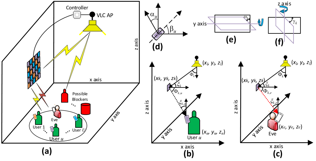
The system model of the considered mirror array-based RIS-aided secure VLC system is illustrated in Fig. 1(a), with a focus on downlink communications. In this figure, a VLC AP mounted on the ceiling serves multiple legitimate users via mirror array-based RISs positioned on the room’s wall. Due to the presence of objects and/or unintended users (i.e., possible blockers) in the room, we consider a non-line-of-sight (NLoS) path between the VLC AP and the intended users. In addition to the legitimate users, there is an eavesdropper, Eve, who attempts to wiretap the secret message for the legitimate users from the reflected signals of the mirror array-based RISs. It is desired to optimize the assignment of the RISs elements to the legitimate users, the orientation of the mirror array-based RISs, and the transmit power of the VLC AP such that the PLS of the system is maximized. Through channel acquisition methods, the controller unit can obtain the spatial locations (and subsequently, the required channel information) of legitimate users, Eve, RIS elements, and the VLC AP [24, 25, 18, 23]. Fig. 1(b) and Fig. 1(c) show the angles of irradiance and incidence of the light signal that propagates from the VLC AP through the -th mirror array-based RIS element to both the -th user and Eve, respectively. For which, and denote an arbitrary user and an arbitrary RIS element, respectively. and denote the number of intended users and the number of RIS elements, respectively. Fig. 1(d) illustrates the user’s device orientation angles, while Fig. 1(e) and Fig. 1(f) show the mirror array-based RIS orientation in respect of its roll angle and yaw angle , respectively. The channel gains for the legitimate users and Eve are elaborated in the sequel.
II-B VLC Channel of Legitimate Users
The NLoS channel gain between the AP and the -th user, considering the signal reflection from the -th RIS element can be expressed as [26]
| (1) |
where is the reflectivity of the RISs, denotes the order of Lambertian emission with the semi-angle at half power of LEDs , represents the physical area of the PD, is the area of the -th reflective surface, is the gain of the optical filter, is the irradiance angle between the AP and the -th RIS element, is the incidence angle between the AP and the -th RIS element, is the irradiance angle between the -th RIS element and the -th user, is the incidence angle between the -th RIS element and the -th user, and is the gain of the optical concentrator which is given by , where and are the refractive index and FoV of the PD, respectively. The variables and denote the link distance between the VLC AP and the -th RIS element and the -th RIS element and the -th user, respectively.
The orientation of the user’s device does not affect the irradiance angles and . However, the incidence angle is heavily impacted by device orientation. In (1), the term captures the impact of random device orientation on the signal reception at the PD and can be expressed as [27]
| (2) |
where and are the Cartesian coordinates for the -th RIS element and the -th user, respectively. and are the polar and azimuth angles of the -th user device, respectively. Considering the orientation angles of the -th RIS element that has been assigned to the -th user (i.e., and ), the cosine of the irradiance angle can be expressed as [28]
| (3) |
II-C VLC Channel of Eve
We assume that Eve has a powerful receiver and can eavesdrop on all the users in the system [29, 30]. The channel gain of the eavesdropped signal of the -th user can be expressed as
| (4) |
where and are given by
| (5) |
and
| (6) |
respectively.
III Adopted Multiple Access Schemes
In this section, the details of the considered -layer RSMA scheme and the power-domain NOMA scheme are presented. In the considered multi-user scenario, the users are sorted based on their channel gains [31]. To facilitate the analysis, a matrix and a vector are defined, respectively, as follows
| (7) |
| (8) |
where G denotes the RIS-user association matrix and is a vector that indicates the RIS elements assigned to the -th user. For example, is a component of , representing an indicator function that determines whether or not the -th RIS element is assigned to the -th user. In this work, we assume that Eve is an internal Eve (i.e., untrusted user), and thus can know the signaling structure of the system to be able to eavesdrop on the -th user signal [32, 33].
III-A RSMA Scheme
The RSMA scheme divides each user’s message into two parts: a private part and a common part. At the VLC AP side, all the common parts are combined into a single message, which is then encoded into a common stream. This common stream is broadcasted to all users along with each user’s private stream. On the user side, all users can decode the common stream, but only the intended user can decode its own private stream. More specifically, using the SIC technique, users can remove the common stream from their received signal, allowing them to decode their private stream while treating other users’ private streams as noise [10]. At the -th user, the received signal can be expressed as
| (9) |
where and are the transmit power coefficients of the common stream and the private stream, respectively. Those transmit power coefficients are continuous variables and the relation between them is given by , where is the VLC AP electrical transmit power, while and denote the -th user common and private streams, respectively. is the real-valued additive Gaussian noise with variance and it includes both the thermal and the shot noises [34].
At the -th user, the message decoding process starts with decoding the common stream and subtracting it from the message through the SIC process. Accordingly, the rate of the -th user decoding the common stream is given as [34]
| (10) |
where represents the inter-user interference term resulting from implementing the RSMA scheme. , , and denote the PD responsivity, the noise power spectral density, and the bandwidth of the system, respectively.
At each user, after subtracting the common stream from the message, the user decodes the private stream while treating other users’ private streams as noise. The rate of decoding the private stream is
| (11) |
where represents the inter-user interference term resulting from implementing the RSMA scheme.
Eve operates similarly to a legitimate user by first decoding the common stream, subtracting it from the eavesdropped user’s message, and subsequently attempting to decode the private user message. Accordingly, the achievable rate of decoding the common stream of the -th user at Eve is
| (12) |
where represents the inter-user interference term resulting from implementing the RSMA scheme. likewise, the achievable rate of decoding the private stream of the -th user at Eve is given by
| (13) |
where represents the inter-user interference term resulting from implementing the RSMA scheme. In general, the SR can be determined by calculating the difference between the achievable rates of the legitimate user and the eavesdropper. Mathematically, the SR for multiple users can be defined as [35]
| (14) |
where , is the achievable rate of the legitimate user, is the achievable rate of the eavesdropper, wiretapping the -th user, and . In this work, we first aim to maximize the minimum secrecy rate, which for the proposed RSMA VLC system is given by [36]
| (15) |
For clarity, (15) is expanded at the bottom of this page.
III-B Power-domain NOMA Scheme
The power-domain NOMA scheme allows several users to share the same radio resource. At the VLC AP side, through the principle of superposition coding, a superposed signal is formed and transmitted to the intended users. On the user side, through the principle of SIC, users’ messages can be decoded [14]. Subsequently, at the -th user, the received signal can be expressed as
| (16) |
where denotes the NOMA power allocation coefficient of the -th user. Based on [37], is given as
| (17) |
where is a constant value in the range of . Also, satisfies the following relation .
Accordingly, through the power-domain NOMA scheme, the decoding rate at the -th user is given as
| (18) |
where represents the inter-user interference term resulting from implementing the power-domain NOMA scheme.
The Eve’s data rate when the -th user is being wiretapped can be expressed as
| (19) |
where and . Thus, the minimum secrecy rate of the proposed NOMA VLC system can be expressed as [38]
| (20) |
where for clarity, (20) is expanded at the top of the next page.
IV Problem Formulation
In this section, the details of the Max-Min secrecy rate optimization problem of both the RSMA and the power-domain NOMA schemes for the proposed combined channel model are presented. This optimization problem simultaneously optimizes several optimizations variables, (i) the VLC AP power allocation coefficients (this variable is represented in the RSMA scheme by and , and in the power-domain NOMA scheme by ), (ii) the RIS elements orientation angles (this variable is represented for both considered schemes by the angles and ), and (iii) the RIS association matrix (this variable is represented for both considered schemes by the matrix G).
IV-A Max-Min Secrecy Rate Optimization
One can express the Max-Min secrecy rate optimization problem of the RSMA scheme as
| (P1): | (21) | ||||
| s.t. | |||||
| (22) | |||||
| (23) | |||||
| (24) | |||||
| (25) | |||||
| (26) | |||||
| (27) | |||||
where the constraint (22) comes from the definition of each entity, , in the RIS-user association matrix, G, which was previously described in (7). The constraint (23) ensures that each RIS element can only serve a particular user at a time. This constraint follows the point source assumption proposed in [26] and is utilized in the context of RIS-aided VLC systems in several works, for example, [17]. The constraints (22) and (23) control the RIS-user association decision variable, the first decision variable in (P1), by setting a binary indicator function to each RIS element to serve a particular user at a time. The constraints (24) and (25) ensure the orientation angles, and , lie within the range of . The goal of these two constraints is to adjust the orientation of each RIS element to steer the light toward the intended receiver. The constraint (26) denotes the VLC AP total electrical transmit power limitation. This constraint is set to ensure that the VLC AP adheres to this power limitation, in addition to efficiently distributing this power between the common and private streams in the adopted RSMA scheme. The constraint (27) guarantees the minimum rate requirements of each user, . Consequently, this constraint ensures a certain quality-of-service (QoS) for all users in the system.
Similarly, one can express the Max-Min secrecy rate optimization problem of the power-domain NOMA scheme as
| (P2): | (28) | |||||
| s.t. | ||||||
| (29) | ||||||
| (30) | ||||||
| (31) | ||||||
| (32) | ||||||
| (33) | ||||||
| (34) | ||||||
where the constraints (33) make sure that the allocated power ratios to each user in the power-domain NOMA scheme are within the VLC AP total electrical transmit power limitation. The constraint (34) guarantees the minimum rate requirements of each user, .
Both (P1) and (P2) are novel optimization problems that have not been considered in the literature yet. These problems are non-convex and include both discrete (i.e., G) and continuous (i.e., , , , and ) optimization variables, classifying them as mixed-integer non-linear programming (MINLP) NP-hard problems. Also, the number of optimization variables that need to be optimized in each of these optimization problems is high. The complexity of (P1) and (P2) are presented in Section V-B. This raises the problems to a greater level of complexity, making them difficult to be solved using conventional methods. The typical approach for such joint optimization problems is by decomposing it into sub-problems. However, due to the structure of the considered objective functions and the multiple mixed integer decision variables, decomposing (P1) and (P2) still yields non-convex sub-problems. Furthermore, such a decomposition approach affects the quality of the solution since the decision variables are not jointly optimized. Therefore, to solve (P1) and (P2) within a reasonable time while ensuring solution quality, we resort to evolutionary metaheuristic algorithms, specifically the GA. It is worth noting that the GA is popular in solving NP-hard problems. This is because this algorithm combines global search capabilities, flexibility, and robustness, which are critical when tackling NP-hard problems with vast and complex solution spaces [39]. Also, the GA often provides an acceptable solution (i.e., a solution that respects the constraints) within a reasonable time, making it highly practical for complex optimization problems. Moreover, the GA has shown efficiency in solving RIS-related optimization problems, as highlighted in [40, 41, 22]. The details of the solution methodology are presented in Section V.
IV-B Max-Min Secrecy Energy Efficiency Optimization
Alongside the secrecy rate, the SEE is a popular performance metric in PLS-aided VLC systems [42, 43, 44]. The SEE metric ensures that the consumed energy of the system is taken into consideration while optimizing the secrecy performance of the system. The SEE can be defined as the “consumed energy per transmitted confidential bits (Bits/Joule)” [44]. Generally, there are three main contributors to the total consumed energy in RIS-aided VLC system, namely, the VLC AP (i.e., Transmitter), RIS, and users (i.e., Receivers) [45]. Subsequently, the total consumed energy in the proposed system is . At the transmitter, , , , , and denote the consumed energy related to the digital-to-analog converter (DAC), the filter, the power amplifier, the LED driver, and the transmitter external circuit, respectively. At the RIS, denotes the consumed energy that is needed to rotate each passive RIS element. At each user, , , , and denote the consumed energy related to the analog-to-digital converter (ADC), the trans-impedance amplifier (TIA), the filter, and the receiver external circuit, respectively. The minimum secrecy rate of the proposed RIS-aided VLC system for both the RSMA and the power-domain NOMA scheme are provided in (15) and (20), respectively. Therefore, the minimum SEE for both the RSMA and the power-domain NOMA scheme can be expressed respectively as
| (35) |
| (36) |
To formulate the Max-Min SEE problem for the considered RSMA scheme, we replace the objective functions of (P1) by (35). Similarly, for the considered NOMA scheme, we replace the objective functions of (P2) by (36). The Max-Min SEE optimization problems can be expressed as
| (P3): | (37) | ||||
and
| (P4): | (38) | ||||
Then, we solve (P3) and (P4) by following the same steps that will be mentioned in Section V. It is worth noting that (P3) and (P4) have fractional objective functions, which adds another level of complexity compared to the involved objective functions in (P1) and (P2). This is an additional reason for considering the GA as a unified solution methodology for all these optimization problems.
V Solution Methodology
V-A Genetic Algorithm-based Approach
The working principle behind the GA is the idea of the “survival of the fittest", whereby the best individuals in an initial randomly generated solution candidates (population of chromosomes) are selected and combined to form the next generation of chromosomes. In our case, an individual can be a RIS-user association variable, RIS elements orientation angles, and power allocation coefficients for the RSMA and the power-domain NOMA schemes. After a predefined number of generations or if the maximum fitness value is reached, the evolution process is stopped, and the surviving chromosomes represent the best solution [46]. Particularly, three types of operators are involved, namely, selection, crossover, and mutation. The selection operator selects a pair of chromosomes according to the tournament method for selecting the best individuals. The crossover operator randomly chooses a locus and exchanges the sub-sequences before and after that locus between the two chromosomes to create two offspring. The mutation operator flips some of the bits in a chromosome to help prevent the algorithm from getting stuck in a local optima. After generating the two offspring, their fitness and feasibility indicators are evaluated. The two offspring replace some chromosomes in the current population according to the following adopted replacement procedure. The two chromosomes with the lowest fitness value and zero feasibility indicator are replaced. If all the chromosomes in the population are feasible, the two chromosomes with the lowest fitness values are replaced.
The GA-based algorithm for a population size , number of generations , and probabilities of crossover and mutation of and , respectively, is summarized in Algorithm 1.
| Parameter name, notation | Value | [#] |
|---|---|---|
| The VLC AP electrical transmit power, | Watt | [47] |
| The number of RIS elements, | [34] | |
| The FoV of the PD, | [31] | |
| The reflection coefficient of the RIS element, | [28] | |
| The half-intensity radiation angle, | [48] | |
| The physical area of the PD, | [49] | |
| The refractive index of the PD, | [34] | |
| The responsivity of the PD, | A/W | [48] |
| The bandwidth of the system, | MHz | [49] |
| The minimum rate requirements of each user, | kbps | [50] |
| The population size in the Genetic algorithm, | [39] | |
| The number of generations in the Genetic algorithm, | [39] | |
| The noise power spectral density, | [31] | |
| The number of intended users, | [34] | |
| The power of the filter, | mWatt | [48] |
| The power of the DAC, | mWatt | [48] |
| The power of the LED driver, | mWatt | [48] |
| The power of the power amplifier, | mWatt | [48] |
| The power of the transmitter external circuit, | mWatt | [48] |
| The consumed energy for rotating an RIS element, | mWatt | [48] |
| The consumed energy of the ADC, | mWatt | [48] |
| The consumed energy of the TIA, | mWatt | [48] |
| The consumed energy of the receiver external circuit, | mWatt | [48] |
V-B Computational Complexity
The computational complexity of Algorithm 1 is composed of the following components:
-
•
Initialization: The time complexity for generating an random chromosomes or individuals is , where is the number of decision variables. In both considered schemes, to optimize G, the required number of decision variables is and to optimize and , the required number of decision variables is . In the RSMA scheme, to optimize and , the required number of decision variables is . On the other hand, to optimize in the power-domain NOMA scheme, the required number of decision variables is one. Overall, and for RSMA and power-domain NOMA schemes, respectively. For example, if is and is , then the required number of decision variables are and for the RSMA and the power-domain NOMA schemes, respectively. It is worth noting that in our proposed system, the power-domain NOMA scheme requires fewer decision variables compared to the RSMA scheme. Consequently, it has less computational complexity.
-
•
Selection: The time complexity of the tournament selection method is [51].
-
•
Crossover and Mutation: The crossover and mutation processes each has a worst-case time complexity of , where is the locus (i.e., crossover point).
-
•
Evaluation: The evaluation of the fitness function for all individuals can be done in parallel and hence has a time complexity .
Accordingly, the overall time complexity can be approximated as .
VI Simulation Results
This section provides detailed numerical results to assess the secrecy performance of the proposed RIS-aided VLC system for the considered RSMA and power-domain NOMA schemes in terms of both the Max-Min SR and the SEE. The default parameters for the simulations are summarized in Table II. Beyond this summary, the polar angle, , is characterized using the Laplace distribution and its value spans over with a mean of and a standard deviation of [27]. The azimuth angle, , is characterized using the uniform distribution, and its value spans over [27]. The users in the system are depicted as cylinders with a height of meters and a radius of meters. The receiver is held by a user standing at a height of meters and a distance of meters from their body. The default size of the considered RIS is , while each element in the RIS is a square with dimensions of cm cm. The dimensions of the room are assumed to be m m m.
VI-A Max-Min Secrecy Rate Results
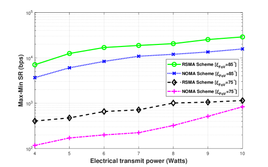
Fig. 2 shows that the proposed RIS-aided VLC system with the RSMA scheme achieves a better Max-Min SR performance compared to the power-domain NOMA scheme. This result indicates that the RSMA scheme is more secure for VLC users than the power-domain NOMA scheme. Specifically, under the same network parameters, a better SR is achieved by the RSMA scheme. Also, this figure shows the effect of changing the PDs FoV on the Max-Min SR performance. It is known that the wider a user PD FoV, the better the chance that the user receives stronger light signals from the closest RIS elements. Consequently, this figure illustrates that even a increase in the users PD FoV can achieve up to -fold enhancement in the SR performance.
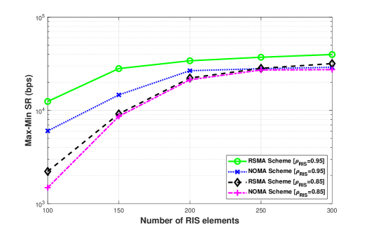
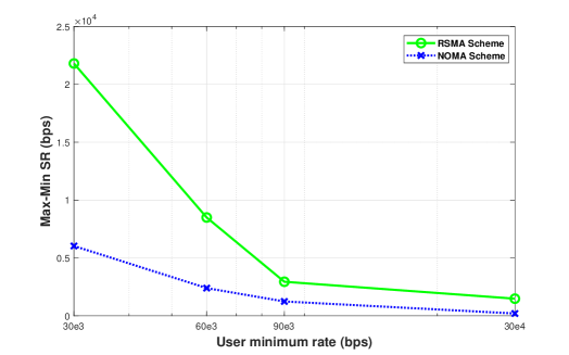
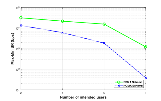
Fig. 3 compares the Max-Min SR performance of the proposed RIS-aided VLC system for both the RSMA and the power-domain NOMA schemes. As expected, as the number of RIS elements increases, the Max-Min SR performance for both schemes increases. It can be observed that this gain increases steadily and then starts to saturate with a high number of elements. This is supported by the fact that adding more elements to a large RIS leads to only marginal improvements. Also, this figure shows the effect of changing the RISs reflectivities, . For best performance, it is important to choose RIS elements with high reflectivities, as a decrease in the elements’ reflectivity can degrade the SR performance by at least .
Fig. 4 demonstrates the Max-Min SR performance versus users’ minimum rate requirement. In this figure, as the required rate increases, more resources are used to satisfy the per-user demand, leading to a decrease in the Max-Min SR. This observation is true for both the RSMA and the power-domain NOMA schemes.
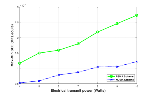
Fig. 5 illustrates the Max-Min SR performance versus the number of intended users. It can be observed that as the number of users in the system increases, the Max-Min SR performance decreases. This can be justified by the fact that the number of resources in the considered RIS-aided VLC system is fixed (i.e., the number of RIS elements that provide intended users with light signals is fixed).
VI-B Max-Min Secrecy Energy Efficiency Results
Fig. 6 compares the Max-Min SEE performance of the proposed RIS-aided VLC system for the RSMA and the power-domain NOMA schemes for different values of the VLC AP electrical transmit power. One can notice that the RSMA scheme achieves a significant performance gain, up to , compared to the power-domain NOMA scheme. This is because the RSMA scheme is more energy efficient compared to the power-domain NOMA scheme [52].
| RIS # |
|
|
RIS # |
|
|
|
|||||||||||||
| User 1 | User 2 | User 1 | User 2 | ||||||||||||||||
| 1 | 0 | 1 | (23.0891°, 15.5374°) | 16 | 0 | 1 | (76.5314°, 72.8200°) |
|
|||||||||||
| 2 | 0 | 1 | (52.5489°, -18.6762°) | 17 | 1 | 0 | (40.6991°, 58.2423°) | ||||||||||||
| 3 | 0 | 1 | (41.8877°, 52.6141°) | 18 | 0 | 1 | (42.4476°, -74.5671°) | ||||||||||||
| 4 | 0 | 1 | (36.4535°, -1.3691°) | 19 | 1 | 0 | (-35.7331°, -5.9635°) | ||||||||||||
| 5 | 0 | 1 | (18.9253°, -48.5019°) | 20 | 1 | 0 | (33.2268°, 55.9919°) | ||||||||||||
| 6 | 0 | 1 | (-22.4593°, 43.0449°) | 21 | 0 | 1 | (-16.5819°, 69.9737°) | ||||||||||||
| 7 | 0 | 1 | (-31.6412°, -5.4666°) | 22 | 0 | 1 | (-18.4175°, -24.0222°) | ||||||||||||
| 8 | 0 | 1 | (-33.4945°, -50.6330°) | 23 | 0 | 1 | (71.5116°, -32.2981°) | ||||||||||||
| 9 | 0 | 1 | (78.7889°, 61.0648°) | 24 | 0 | 1 | (69.8503°, 8.6299°) | ||||||||||||
| 10 | 0 | 1 | (-33.1080°, -29.6117°) | 25 | 1 | 0 | (-80.1327°, -78.3159°) | ||||||||||||
| 11 | 0 | 1 | (-74.2463°, 75.4771°) | 26 | 0 | 1 | (-34.0116°, -56.7357°) | ||||||||||||
| 12 | 0 | 1 | (-54.7316°, 32.5004°) | 27 | 1 | 0 | (-27.0498°, -84.5888°) | ||||||||||||
| 13 | 0 | 1 | (-59.5423°, -25.6850°) | 28 | 0 | 1 | (-64.2131°, -9.1779°) | ||||||||||||
| 14 | 0 | 1 | (50.7947°, 5.1178°) | 29 | 0 | 1 | (64.6667°, -29.3755°) | ||||||||||||
| 15 | 0 | 1 | (56.3838°, -17.5380°) | 30 | 1 | 0 | (-29.4845°, 79.1200°) | ||||||||||||
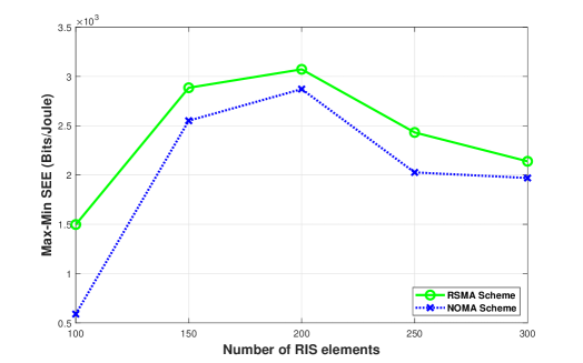
Fig. 7 compares the Max-Min SEE performance of the proposed RIS-aided VLC system for both the RSMA and the power-domain NOMA schemes for a different number of RIS elements. In this figure, as the number of RIS elements grows, we observe that the SEE reaches a peak and then starts to decrease. By examining (35) or (36), this trend can be explained by the logarithmic increase followed by the saturation behavior in SR, the numerator, as illustrated in Fig. 3, and the linear increase in the total consumed energy, the denominator, with more RIS elements. Practically, when the number of RIS elements is high, the SR improvement becomes unnoticeable, and the total consumed energy keeps increasing linearly. With such deployment, the system becomes energy-inefficient. Also, this figure shows that, for both scenarios, the best SEE performance can be achieved when the mirror array-based RIS contains two hundred elements. At this point, both schemes strike a favorable balance between the SR improvement and the total energy consumption.
VI-C Convergence, Benchmarking, and Optimization Decision Variables Example
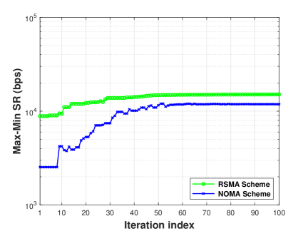
In this subsection, we present some results to provide deep insights into the adopted solution methodology and the optimized decision variables. For consistency, it is worth noting that the presented results are simulated while considering the following parameters: Watts, , and . Fig. 8 shows the convergence curves of the GA algorithm for the proposed mirror array-based RIS-aided secure VLC system for both the RSMA and the power-domain NOMA schemes. For both schemes, the GA converges in less than iterations.
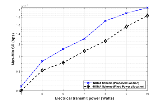
In Fig. 9, our proposed power-domain NOMA-based RIS-aided VLC system that jointly optimizes the VLC AP power allocation, RIS association, and RIS elements orientation angles is benchmarked with a counterpart system that uses a fixed power allocation scheme and jointly optimizes both the RIS association and orientation using Algorithm 1 [53]. To achieve the fixed power allocation scheme, the parameter is set to [34]. Subsequently, the VLC AP power allocation coefficient variables (i.e., ) are turned into constant values. This figure demonstrates that the proposed system achieves up to 135% improvement in the Max-Min SR performance compared to the counterpart scheme.
To better visualize the VLC AP power allocation, RIS association, and RIS elements orientation angles decision variables, an illustration is provided in Table III. Specifically, a concrete and compact example of the optimized decision variables for the RSMA scheme is presented. As shown in the table, the entries of the RIS association matrix G are binary variables that take a value of either or . The RIS orientation angles variables () lie within the range of . It should be noted that negative angles cause reflections in a specific direction, while positive angles cause reflections in the opposite direction [19]. Lastly, the VLC AP power allocation variables () are continuous variables that fall within the range of (). In this example, given the aforementioned simulation parameters, the number of decision variables is . Also, as depicted in Table III, the number of elements allocated for User and User appears to be and , respectively. Such RIS element allocation achieves the minimum rate requirements of both users. Moreover, one can notice from the last column of Table III that most of the VLC AP transmit power is allocated for the common stream (i.e., ) compared to the allocated powers for the private streams (i.e., and ). This is expected and consistent with the SIC requirements in RSMA-based systems [54].
VII Conclusion and Future Research Directions
This paper proposes and evaluates two optimization frameworks that maximize both the minimum SR and the minimum SEE for both power-domain NOMA and RSMA-based VLC systems. Specifically, the proposed frameworks jointly consider the orientation angles of the RIS elements, the association matrix, and the power allocation coefficients and then jointly solve the formulated problems through the GA. To ensure efficient utilization of network resources, achieve high network spectral and energy efficiencies, and enhance user fairness, both the RSMA and the power-domain NOMA schemes are investigated. Also, our proposed model incorporates the random device orientation to extend the practicality and robustness of the considered RIS-aided VLC system. Comprehensive simulations are presented and revealed that the RSMA scheme outperforms the power-domain NOMA scheme in the proposed system, based on both the SR and SEE metrics and on various network parameters. In the future, we plan to (i) evaluate the proposed system in a larger room with multiple VLC APs, (ii) analyze the impact of obstacles and (iii) extend the proposed framework to incorporate the peak-to-average-power-ratio (PAPR) constraint.
References
- [1] P. H. Pathak, X. Feng, P. Hu, and P. Mohapatra, “Visible light communication, networking, and sensing: A survey, potential and challenges,” IEEE Commun. Surv. Tutor., vol. 17, no. 4, pp. 2047–2077, 4th Quart. 2015.
- [2] N. Chi, Y. Zhou, Y. Wei, and F. Hu, “Visible light communication in 6G: Advances, challenges, and prospects,” IEEE Veh. Technol. Mag., vol. 15, no. 4, pp. 93–102, Sep. 2020.
- [3] L. E. M. Matheus, A. B. Vieira, L. F. M. Vieira, M. A. M. Vieira, and O. Gnawali, “Visible light communication: Concepts, applications and challenges,” IEEE Commun. Surv. Tutor., vol. 21, no. 4, pp. 3204–3237, 4th Quart. 2019.
- [4] S. Al-Ahmadi, O. Maraqa, M. Uysal, and S. M. Sait, “Multi-user visible light communications: State-of-the-art and future directions,” IEEE Access, vol. 6, pp. 70 555–70 571, 2018.
- [5] M. H. Khoshafa, O. Maraqa, J. M. Moualeu, S. Aboagye, T. M. N. Ngatched, M. H. Ahmed, Y. Gadallah, and M. D. Renzo, “RIS-assisted physical layer security in emerging RF and optical wireless communication systems: A comprehensive survey,” IEEE Commun. Surv. Tutor., pp. 1–1, early access, 2024.
- [6] S. Aboagye, A. R. Ndjiongue, T. M. N. Ngatched, O. A. Dobre, and H. V. Poor, “RIS-assisted visible light communication systems: A tutorial,” IEEE Commun. Surv. Tutor., vol. 25, no. 1, pp. 251–288, 1st Quart. 2023.
- [7] Y. Chen, Y. Wang, J. Zhang, P. Zhang, and L. Hanzo, “Reconfigurable intelligent surface (RIS)-aided vehicular networks: Their protocols, resource allocation, and performance,” IEEE Veh. Technol. Mag., vol. 17, no. 2, pp. 26–36, Jun. 2022.
- [8] Y. Chen, Y. Wang, X. Guo, Z. Han, and P. Zhang, “Location tracking for reconfigurable intelligent surfaces aided vehicle platoons: Diverse sparsities inspired approaches,” IEEE J. Sel. Areas Commun., vol. 41, no. 8, pp. 2476–2496, Aug. 2023.
- [9] Y. Chen, Y. Wang, and Z. Wang, “Reconfigurable intelligent surface aided high-mobility millimeter wave communications with dynamic dual-structured sparsity,” IEEE Trans. Wireless Commun., vol. 22, no. 7, pp. 4580–4599, Jul. 2023.
- [10] Y. Mao, O. Dizdar, B. Clerckx, R. Schober, P. Popovski, and H. V. Poor, “Rate-splitting multiple access: Fundamentals, survey, and future research trends,” IEEE Commun. Surv. Tutor., vol. 24, no. 4, pp. 2073–2126, 4th Quart. 2022.
- [11] B. Clerckx, Y. Mao, E. A. Jorswieck, J. Yuan, D. J. Love, E. Erkip, and D. Niyato, “A primer on rate-splitting multiple access: Tutorial, myths, and frequently asked questions,” IEEE J. Sel. Areas Commun., vol. 41, no. 5, pp. 1265–1308, May 2023.
- [12] S. Han, H. Xia, X. Zhou, and C. Li, “Securing RSMA-based communications at physical layer,” IEEE Netw., vol. 38, no. 2, pp. 211–217, Mar. 2024.
- [13] H. Bastami, M. Letafati, M. Moradikia, A. Abdelhadi, H. Behroozi, and L. Hanzo, “On the physical layer security of the cooperative rate-splitting-aided downlink in UAV networks,” IEEE Trans. Inf. Forensics Secur., vol. 16, pp. 5018–5033, Nov. 2021.
- [14] O. Maraqa, A. S. Rajasekaran, S. Al-Ahmadi, H. Yanikomeroglu, and S. M. Sait, “A survey of rate-optimal power domain NOMA with enabling technologies of future wireless networks,” IEEE Commun. Surv. Tutor., vol. 22, no. 4, pp. 2192–2235, 4th Quart. 2020.
- [15] S. Pakravan, J.-Y. Chouinard, X. Li, M. Zeng, W. Hao, Q.-V. Pham, and O. A. Dobre, “Physical layer security for NOMA systems: Requirements, issues, and recommendations,” IEEE Internet Things J., vol. 10, no. 24, pp. 21 721–21 737, Dec. 2023.
- [16] N. T. and B. A. V., “Full-duplex cooperative NOMA network with multiple eavesdroppers and non-ideal system imperfections: Analysis of physical layer security and validation using deep learning,” IEEE Trans. Veh. Technol., vol. 73, no. 11, pp. 17 192–17 208, Nov. 2024.
- [17] S. Sun, F. Yang, J. Song, and Z. Han, “Optimization on multiuser physical layer security of intelligent reflecting surface-aided VLC,” IEEE Wirel. Commun. Lett., vol. 11, no. 7, pp. 1344–1348, Jul. 2022.
- [18] D. A. Saifaldeen, B. S. Ciftler, M. M. Abdallah, and K. A. Qaraqe, “DRL-based IRS-assisted secure visible light communications,” IEEE Photonics J., vol. 14, no. 6, pp. 1–9, Dec. 2022.
- [19] D. A. Saifaldeen, A. M. Al-Baseer, B. S. Ciftler, M. M. Abdallah, and K. A. Qaraqe, “DRL-based IRS-assisted secure hybrid visible light and mmWave communications,” IEEE Open J. Commun. Soc., vol. 5, pp. 3007–3020, 2024.
- [20] J.-Y. Wang, L.-H. Hong, N. Liu, H.-N. Yang, P. Feng, and J. Ren, “Secrecy analysis and optimization for IRMA-and jammer-aided visible light communications,” IEEE Wirel. Commun. Lett., vol. 13, no. 7, pp. 1908–1912, Jul. 2024.
- [21] L. Qian, X. Chi, L. Zhao, and A. Chaaban, “Secure visible light communications via intelligent reflecting surfaces,” in IEEE Int. Conf. Commun. (ICC), Montreal, QC, Canada, Jun. 2021, pp. 1–6.
- [22] R. Iqbal, M. Biagi, A. Zoha, M. A. Imran, and H. Abumarshoud, “Leveraging IRS induced time delay for enhanced physical layer security in VLC systems,” IEEE Wirel. Commun. Lett., vol. 13, no. 11, pp. 3147–3151, Nov. 2024.
- [23] H. Abumarshoud, C. Chen, I. Tavakkolnia, H. Haas, and M. A. Imran, “Intelligent reflecting surfaces for enhanced physical layer security in NOMA VLC systems,” in IEEE Int. Conf. Commun. (ICC), Rome, Italy, May 2023, pp. 3284–3289.
- [24] Z. Liu, F. Yang, S. Sun, J. Song, and Z. Han, “Physical layer security in NOMA-based VLC systems with optical intelligent reflecting surface: A Max-Min secrecy data rate perspective,” IEEE Internet Things J., vol. 12, no. 6, pp. 7180–7194, Mar. 2025.
- [25] X. Chen and M. Jiang, “Adaptive statistical bayesian MMSE channel estimation for visible light communication,” IEEE Trans. Signal Process., vol. 65, no. 5, pp. 1287–1299, Mar. 2017.
- [26] A. M. Abdelhady, A. K. S. Salem, O. Amin, B. Shihada, and M.-S. Alouini, “Visible light communications via intelligent reflecting surfaces: Metasurfaces vs mirror arrays,” IEEE Open J. Commun. Soc., vol. 2, pp. 1–20, 2021.
- [27] M. D. Soltani, A. A. Purwita, Z. Zeng, H. Haas, and M. Safari, “Modeling the random orientation of mobile devices: Measurement, analysis and LiFi use case,” IEEE Trans. Commun., vol. 67, no. 3, pp. 2157–2172, Mar. 2019.
- [28] S. Aboagye, T. M. N. Ngatched, O. A. Dobre, and A. R. Ndjiongue, “Intelligent reflecting surface-aided indoor visible light communication systems,” IEEE Commun. Lett., vol. 25, no. 12, pp. 3913–3917, Dec. 2021.
- [29] S. Cho, G. Chen, and J. P. Coon, “Cooperative beamforming and jamming for secure VLC system in the presence of active and passive eavesdroppers,” IEEE Trans. Green Commun. Netw., vol. 5, no. 4, pp. 1988–1998, Dec. 2021.
- [30] F. Rottenberg, T.-H. Nguyen, J.-M. Dricot, F. Horlin, and J. Louveaux, “CSI-based versus RSS-based secret-key generation under correlated eavesdropping,” IEEE Trans. Commun., vol. 69, no. 3, pp. 1868–1881, Mar. 2021.
- [31] O. Maraqa, U. F. Siddiqi, S. Al-Ahmadi, and S. M. Sait, “On the achievable Max-Min user rates in multi-carrier centralized NOMA-VLC networks,” Sensors, vol. 21, no. 11, p. 3705, May 2021.
- [32] K. Cao, B. Wang, H. Ding, T. Li, J. Tian, and F. Gong, “Secure transmission designs for NOMA systems against internal and external eavesdropping,” IEEE Trans. Inf. Forensics Secur., vol. 15, pp. 2930–2943, 2020.
- [33] M. Abolpour, S. Aïssa, L. Musavian, and A. Bhowal, “Rate splitting in the presence of untrusted users: Outage and secrecy outage performances,” IEEE Open J. Commun. Soc., vol. 3, pp. 921–935, 2022.
- [34] O. Maraqa, S. Aboagye, and T. M. N. Ngatched, “Optical STAR-RIS-aided VLC systems: RSMA versus NOMA,” IEEE Open J. Commun. Soc., vol. 5, pp. 430–441, 2024.
- [35] H.-M. Wang and T.-X. Zheng, Physical Layer Security in Random Cellular Networks. Singapore: Springer, 2016.
- [36] H. Fu, S. Feng, W. Tang, and D. W. K. Ng, “Robust secure beamforming design for two-user downlink MISO rate-splitting systems,” IEEE Trans. Wirel. Commun., vol. 19, no. 12, pp. 8351–8365, Dec. 2020.
- [37] T. Shen, V. Yachongka, Y. Hama, and H. Ochiai, “Secrecy design of indoor visible light communication network under downlink NOMA transmission,” arXiv preprint arXiv:2304.08458, Apr. 2023.
- [38] C. Du, F. Zhang, S. Ma, Y. Tang, H. Li, H. Wang, and S. Li, “Secure transmission for downlink NOMA visible light communication networks,” IEEE Access, vol. 7, pp. 65 332–65 341, 2019.
- [39] S. M. Sait and H. Youssef, Iterative Computer Algorithms with Applications in Engineering: Solving Combinatorial Optimization Problems. Los Alamitos, CA, USA: IEEE Computer Society Press, 1999.
- [40] H. Wang, Z. Han, and A. L. Swindlehurst, “Channel reciprocity attacks using intelligent surfaces with non-diagonal phase shifts,” IEEE Open J. Commun. Soc., vol. 5, pp. 1469–1485, 2024.
- [41] S. Abdeljabar, M. W. Eltokhey, and M.-S. Alouini, “Sum rate and fairness optimization in RIS-assisted VLC systems,” IEEE Open J. Commun. Soc., vol. 5, pp. 2555–2566, 2024.
- [42] S. T. Duong, T. V. Pham, C. T. Nguyen, and A. T. Pham, “Energy-efficient precoding designs for multi-user visible light communication systems with confidential messages,” IEEE Trans. Green Commun. Netw., vol. 5, no. 4, pp. 1974–1987, Dec. 2021.
- [43] D. R. Pattanayak, V. K. Dwivedi, V. Karwal, A. Upadhya, H. Lei, and G. Singh, “Secure transmission for energy efficient parallel mixed FSO/RF system in presence of independent eavesdroppers,” IEEE Photonics J., vol. 14, no. 1, pp. 1–14, Feb. 2022.
- [44] T. V. Pham, A. T. Pham, and S. Ishihara, “Design of energy-efficient artificial noise for physical layer security in visible light communications,” IEEE Trans. Green Commun. Netw., vol. 8, no. 2, pp. 741–755, Jun. 2024.
- [45] S. Ma, T. Zhang, S. Lu, H. Li, Z. Wu, and S. Li, “Energy efficiency of SISO and MISO in visible light communication systems,” J. Light. Technol., vol. 36, no. 12, pp. 2499–2509, Jun. 2018.
- [46] M. Mitchell, An Introduction to Genetic Algorithms. MIT press, 1998.
- [47] S. Feng, T. Bai, and L. Hanzo, “Joint power allocation for the multi-user NOMA-downlink in a power-line-fed VLC network,” IEEE Trans. Veh. Tech., vol. 68, no. 5, pp. 5185–5190, May 2019.
- [48] O. Maraqa and T. M. N. Ngatched, “Optimized design of joint mirror array and liquid crystal-based RIS-aided VLC systems,” IEEE Photon. J., vol. 15, no. 4, pp. 1–11, Jul. 2023.
- [49] R. Ahiaklo-Kuz, S. Aboagye, O. Maraqa, and T. M. N. Ngatched, “Design and optimization of an integrated visible light communication and localization system using liquid crystal based-RIS receivers,” IEEE Photonics J., vol. 17, no. 3, pp. 1–9, Jun. 2025.
- [50] A. Rasti-Meymandi, A. Madahian, J. Abouei, A. Mirvakili, Z. HajiAkhondi-Meybodi, A. Mohammadi, and M. Uysal, “Design and implementation of VLC-based smart barrier gate systems,” AEU-International Journal of Electronics and Communications, vol. 136, p. 153765, Jul. 2021.
- [51] V. V. De Melo, D. V. Vargas, and W. Banzhaf, “Batch tournament selection for genetic programming: the quality of lexicase, the speed of tournament,” in Proc. Genet. Evol. Comput. Conf. (GECCO), Prague, Czech Republic, Jul. 2019, pp. 994–1002.
- [52] Y. Mao, B. Clerckx, and V. O. Li, “Energy efficiency of rate-splitting multiple access, and performance benefits over SDMA and NOMA,” in Int. Symp. Wirel. Commun. Syst. (ISWCS), Lisbon, Portugal, Aug. 2018, pp. 1–5.
- [53] H. Marshoud, P. C. Sofotasios, S. Muhaidat, G. K. Karagiannidis, and B. S. Sharif, “On the performance of visible light communication systems with non-orthogonal multiple access,” IEEE Trans. Wirel. Commun., vol. 16, no. 10, pp. 6350–6364, Oct. 2017.
- [54] Z. Yang, M. Chen, W. Saad, and M. Shikh-Bahaei, “Optimization of rate allocation and power control for rate splitting multiple access (RSMA),” IEEE Trans. Commun., vol. 69, no. 9, pp. 5988–6002, Sep. 2021.
![[Uncaptioned image]](/html/2505.04893/assets/x10.png) |
Omar Maraqa received the B.Eng. degree in Electrical Engineering from Palestine Polytechnic University, Palestine, in 2011, the M.Sc. degree in Computer Engineering and the Ph.D. degree in Electrical Engineering from King Fahd University of Petroleum & Minerals (KFUPM), Dhahran, Saudi Arabia, in 2017 and 2022, respectively. He is currently a Postdoctoral Research Fellow with the Department of Electrical and Computer Engineering, at McMaster University, Canada. He was recognized as an exemplary reviewer for IEEE Communications Letters in 2023. He serves as a Technical Program Committee (TPC) Member for the IEEE Vehicular Technology Conference, and a reviewer for several IEEE journals. His research interests include optimization and performance analysis of emerging wireless communications systems. |
![[Uncaptioned image]](/html/2505.04893/assets/x11.png) |
Sylvester Aboagye (Member, IEEE) received the B.Sc. degree (Hons.) in telecommunication engineering from the Kwame Nkrumah University of Science and Technology, Kumasi, Ghana, in 2015, and the M.Eng. and Ph.D. degrees in electrical engineering from Memorial University, St. John’s, NL, Canada, in 2018 and 2022, respectively. He received many prestigious awards, including the Governor General’s Academic Gold Medal. He was a Postdoctoral Research Fellow with the Department of Electrical Engineering and Computer Science at York University, Canada, from January to December 2023, and is currently an Assistant Professor with the School of Engineering, University of Guelph, Canada. His current research interests include the design and optimization of multiband wireless networks, visible light communication systems, terrestrial and non-terrestrial integrated sensing and communication networks, and 6G and beyond enabling technologies. Dr. Aboagye serves as an Editor for IEEE Communications Letters and IEEE Open Journal of the Communications Society, a Technical Program Committee (TPC) member for the IEEE Vehicular Technology Conference, and a reviewer for several IEEE journals. He was recognized as an Exemplary Reviewer by IEEE Communications Letters and IEEE Transactions on Network Science and Engineering in 2023. |
![[Uncaptioned image]](/html/2505.04893/assets/x12.png) |
Majid H. Khoshafa (Senior Member, IEEE) received his B.Sc. in Communication Engineering from Ibb University, Yemen, in 2007, his M.Sc. in Telecommunications Engineering from King Fahd University of Petroleum and Minerals (KFUPM), Saudi Arabia, in 2017, and his Ph.D. in Electrical and Computer Engineering from Memorial University of Newfoundland (MUN), Canada, in 2022. From 2009 to 2010, he worked as a Radio Network Planning and Optimization Engineer at MTN Telecommunications, Sana’a, Yemen. From 2010 to 2013, he worked as a Lecturer Assistant in the Electrical and Computer Department, Faculty of Engineering, Ibb University, Ibb, Yemen. He is currently a Postdoctoral Fellow in the Department of Electrical and Computer Engineering at McMaster University, Canada. Previously, he was a Postdoctoral Research Fellow at Queen’s University, Canada, from 2022 to 2023. His research interests include wireless communications, reconfigurable intelligent surface (RIS) technology, physical layer security, AI, and 6G and beyond enabling technologies. He has received several awards from MUN, including the Fellowship of the School of Graduate Studies, the Recognition of Excellence Award, the International Student Recognition Award, and the Graduate Academic Excellence Award. He serves as a Technical Program Committee (TPC) Member for the IEEE Vehicular Technology Conference and a Reviewer for several IEEE journals. He was recognized as an Exemplary Reviewer of IEEE Wireless Communications Letters and IEEE Communications Letters in 2024. |
![[Uncaptioned image]](/html/2505.04893/assets/x13.png) |
Telex M. N. Ngatched (Senior Member, IEEE) received the B.Sc. degree and the M.Sc. degree in electronics from the University of Yaoundé, Cameroon, in 1992 and 1993, respectively, the MscEng (Cum Laude) in electronic engineering from the University of Natal, Durban, South Africa, in 2002, and the Ph.D. in electronic engineering from the University of KwaZulu-Natal, Durban, South Africa, in 2006. From July 2006 to December 2007, he was with the University of KwaZulu-Natal as a Postdoctoral Fellow, from 2008 to 2012 with the Department of Electrical and Computer Engineering, University of Manitoba, Canada, as a Research Associate, and from 2012 to 2022 with Memorial University. He joined McMaster University in January 2023, where he is currently an Associate Professor. His research interests include 5G and 6G enabling technologies, optical wireless communications, hybrid optical wireless and radio frequency communications, artificial intelligence and machine learning for communications, and underwater communications. Dr. Ngatched serves as an Area Editor for the IEEE Open Journal of the Communications Society, an Associate Technical Editor for the IEEE Communications Magazine, and an Editor of the IEEE Communications Society On-Line Content. He was a recipient of the Best Paper Award at the IEEE Wireless Communications and Networking Conference (WCNC) in 2019. He is a Professional Engineer (P. Eng.) registered with the Professional Engineers Ontario, Toronto, ON, Canada. |