All-dielectric metasurface polarization scrambler for imaging applications
††journal: opticajournal††articletype: Research ArticlePolarization scramblers are essential for many imaging applications involving polarization sensitive instruments and partially polarized fluxes. In such cases, the light must be depolarized to allow properly calibrated measurements. Several types of depolarizers are already in use, but none is optimal due to the inevitable image degradation associated with the scrambling process. Here, we present a device based on an all-dielectric metasurface using anisotropic scatterers capable of generating multiple polarization states by varying their orientation angle. Our new scrambling solution allows a massive reduction in the integrated degree of polarization and thus the spatial depolarization of any incident linear polarization, while allowing easier integration into the instrument design and reducing the impact on its image quality.
1 Introduction
Earth radiance has the property of being partially polarized. This partial linear polarization is variable and depends on phenomena such as Rayleigh scattering from aerosol clouds or reflection from the ground. Unfortunately, this uncontrolled state of polarization can be the source of radiometric errors when some parts of an instrument used to observe or monitor the Earth from space have their own polarization signature, as is often the case with multi- or hyperspectral imagers. It is therefore necessary to have a device capable of depolarizing the light before it enters the instrument, i.e. a polarization scrambler.
Several types of scramblers have been developed to address this question. The first, known as the Lyot depolarizer, combines two quartz wedge crystals aligned at an angle of between the two optical axes, and can achieve spectral depolarization under broadband illumination [1]. However, the proper operation of this type of depolarizer is compromised when working with narrow bandwidths. This limitation can be overcome by using scramblers based on temporal or spatial depolarization. Since passive components are preferred when considering the requirements of space applications, most of the scramblers used in optical payloads involve combinations of prisms that allow spatial depolarization by imposing polarization-dependent phase delays that vary across the pupil[2, 3]. The main limitation of this type of scrambler is the degradation of image quality caused by the scrambling process, which makes it difficult to use in imaging systems. Current scrambling technologies induce a "diamond effect" that splits the instrument’s point spread function (PSF) into multiple spots on the detector, depending on the incident polarization state[2, 4]. Today, no solution is truly optimal, so it is interesting to explore new methods and find a better trade-off between depolarization and image quality.
Metasurfaces are planar devices that are spatially structured at the wavelength scale. They have recently emerged as a new technology capable of pushing the boundaries of traditional optical components by allowing sub-wavelength control of light properties[5], enabling ultra-thin and high quality components such as meta-lenses[6, 7], miniaturized spectrometers[8], or even full Stokes polarization cameras[9]. They therefore seem well suited for our application, which requires extensive polarization control[10].
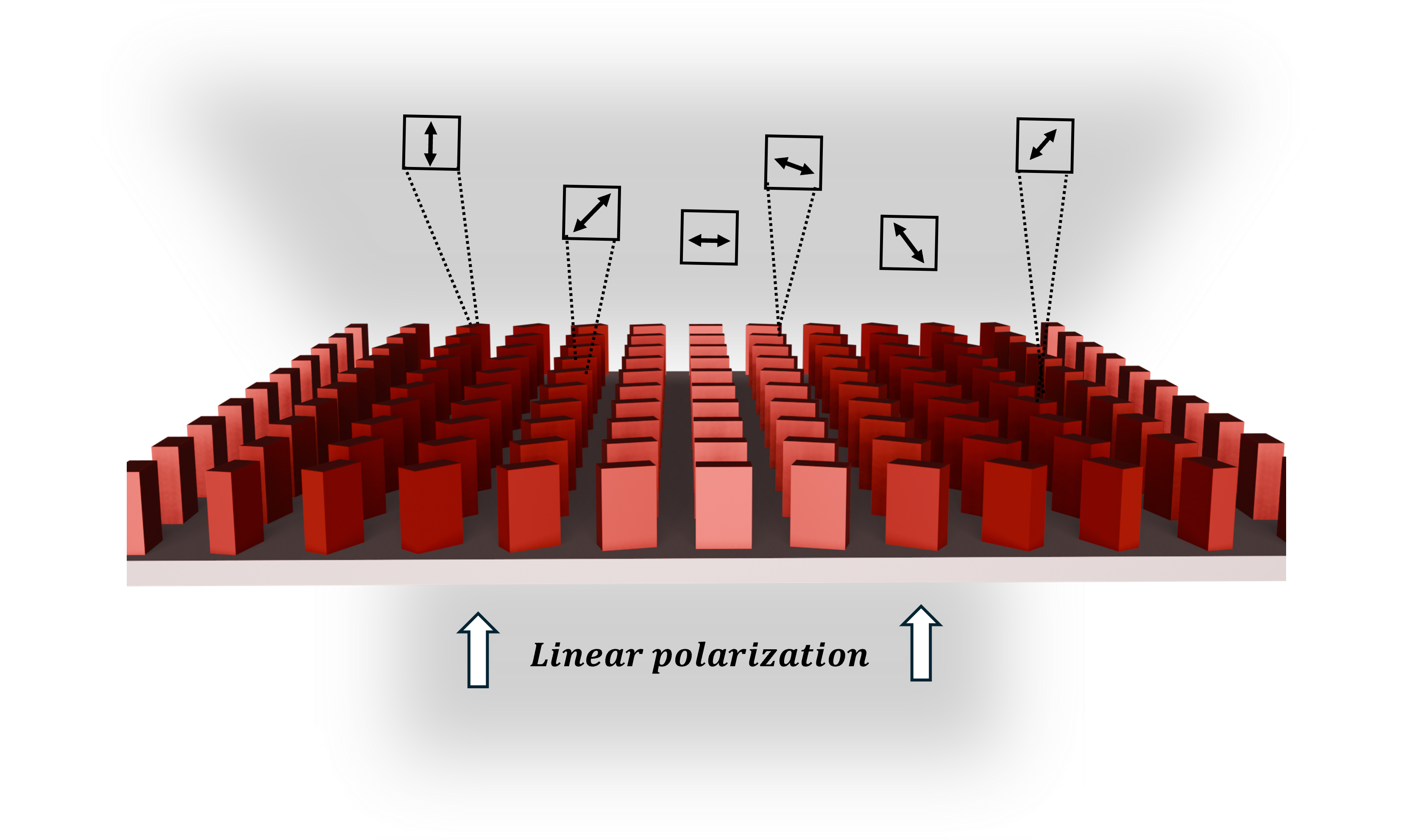
It has already been shown that metasurfaces happen to be a promising solution for both temporal [11] and spatial depolarization [12, 13]. Our work aims to go beyond what has been done by presenting an all-dielectric metasurface that allows spatial depolarization of any linear incident polarization, with quasi-perfect transmission and a reduced impact on image quality. Our work is based on the use of subwavelength arrays of high refractive index dielectric nanoresonators (scatterers) with identical anisotropic shape but different orientations. Anisotropic scatterers introduce shape birefringence and phase jumps. Their subwavelength dimensions are optimized so that the scatterers behave similarly to half-wave plates[14]. The scatterers will thus rotate linear polarization states like a half-wave plate would. The idea of our work is then to use a large number of these scatterers on a metasurface and to vary the orientations of their fast axis. In this way, it will be possible to generate a wide range of local output polarization states across the device, allowing any linear incident polarization to be scrambled.
The performance of our device is quantified by the reduction of the integrated Degree of Polarization (DoP) and the preservation of the quality of the PSF. Thus, the goal of this work is to develop a new polarization scrambling solution for imaging applications that would overcome the current problems of prism-based scramblers. Therefore, Section 2 presents the methodology used to design and optimize the metasurface unit cell. Section 3 describes the formalism used to quantify the depolarization performance. In Section 4, these tools are applied to different metasurface configurations, for which we evaluate the depolarization capabilities as well as the induced image degradation. Finally, in Section 5, we take an interest in the specific case of the MicroCarb instrument[15], and describe how to adapt our device to operate on the 4 different wavebands of this instrument.
2 Unit Cell Design and Optimization
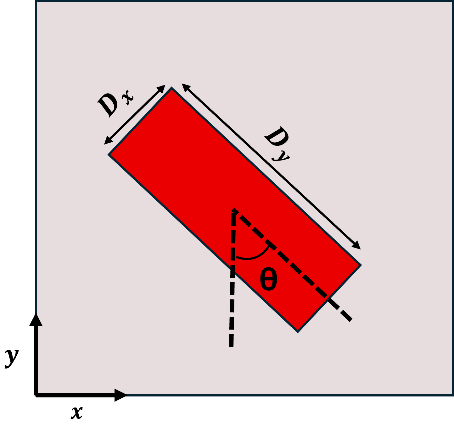
The first step in the process is to define the unit cell (or meta-atom) that will be used to build the metasurface. This unit cell is here formed by a rectangular pillar of titanium dioxide (length , width , height ) located in the center of an elementary square area of a silica substrate (side ), as shown in Fig.1. The choice of dielectric materials such as TiO2 and SiO2 improves the efficiency and compactness of our device by minimizing losses and allowing it to operate in transmission mode.
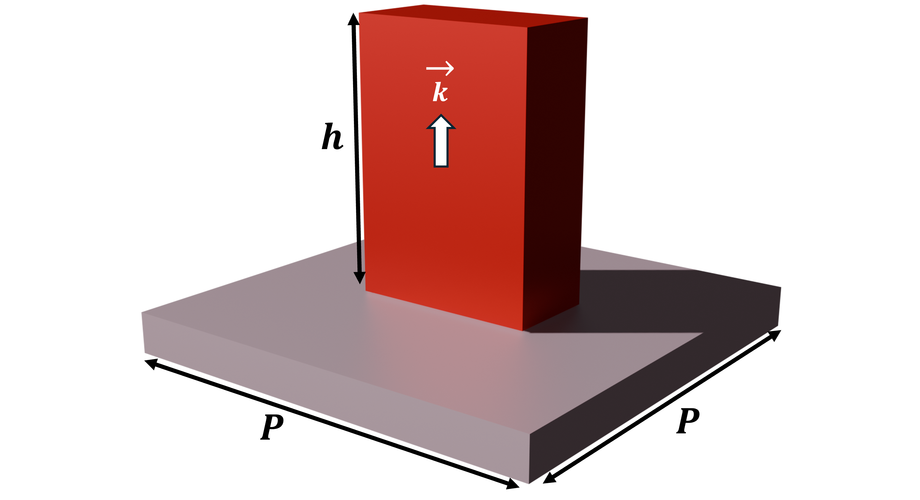
The anisotropic nature of the scatterer (rectangular shape) induces a form birefringence, which is particularly well suited for polarization control applications[10]. The unit cell can be represented by a Jones matrix J
| (1) |
where and are the complex transmission coefficients along the fast and slow axes of the meta-atom. The off-diagonal coefficients and are very close to zero but we still take them into account. The form birefringence allows the pillars to behave like waveplates, by inducing a phase difference between their fast and slow axes. The value of this phase difference can be tuned by playing with the dimensions of the pillars[16] to make their behavior as close as possible to that of a half-wave plate, represented by the Jones matrix . To find the optimal shape of the pillar, it is necessary to define a cost function, that quantifies the distance between the polarimetric properties of the pillar and those of a perfect half-wave plate: we have chosen the quantity , as defined in equation (1).
The modeling of the optical properties of a pillar is carried out by means of a rigorous coupled wave analysis (RCWA) performed by a solver (Lumerical) commercialized by ANSYS. For each set of geometric parameters, this solver considers a 2D periodic replication of the corresponding unit cell, calculates the Jones matrix J from which we can retrieve the value of the associated cost function . An example of the result is shown in Fig. 2, when the two optimized parameters at a wavelength of 763 nm are the width and the length of the pillar, when the height of the pillar and the side of the unit cell are kept constant and equal to 1000 nm and 500 nm, respectively.
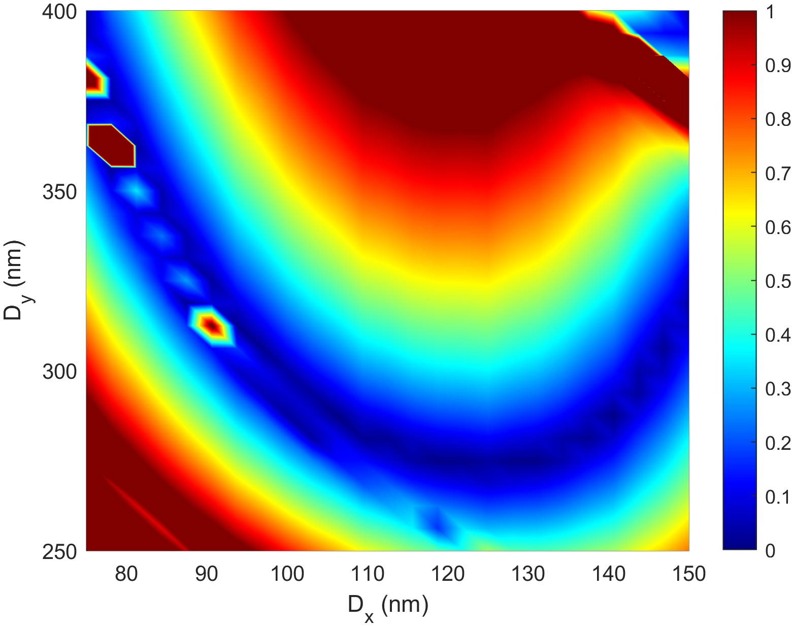
The optimized values of the two parameters are nm and nm (corresponding cost function ), for a global transmission of the unit cell greater than 96% for any incident linear polarization.
3 Building the Metasurface
All scatterers at the surface of the polarization scrambler are characterized by the same geometric parameters, and the only difference between them is the orientation angle of the pillar (see Fig. 3(a)). As a first approximation, the Jones matrix of a pillar rotated by an angle is defined by the following equation involving the rotation matrices and [17]
This expression for models the rotation of an entire array of identical pillars by an angle , which is not exactly the same as rotating each pillar by an angle around its own axis, the difference being illustrated in Fig.3(b).
| (2) |
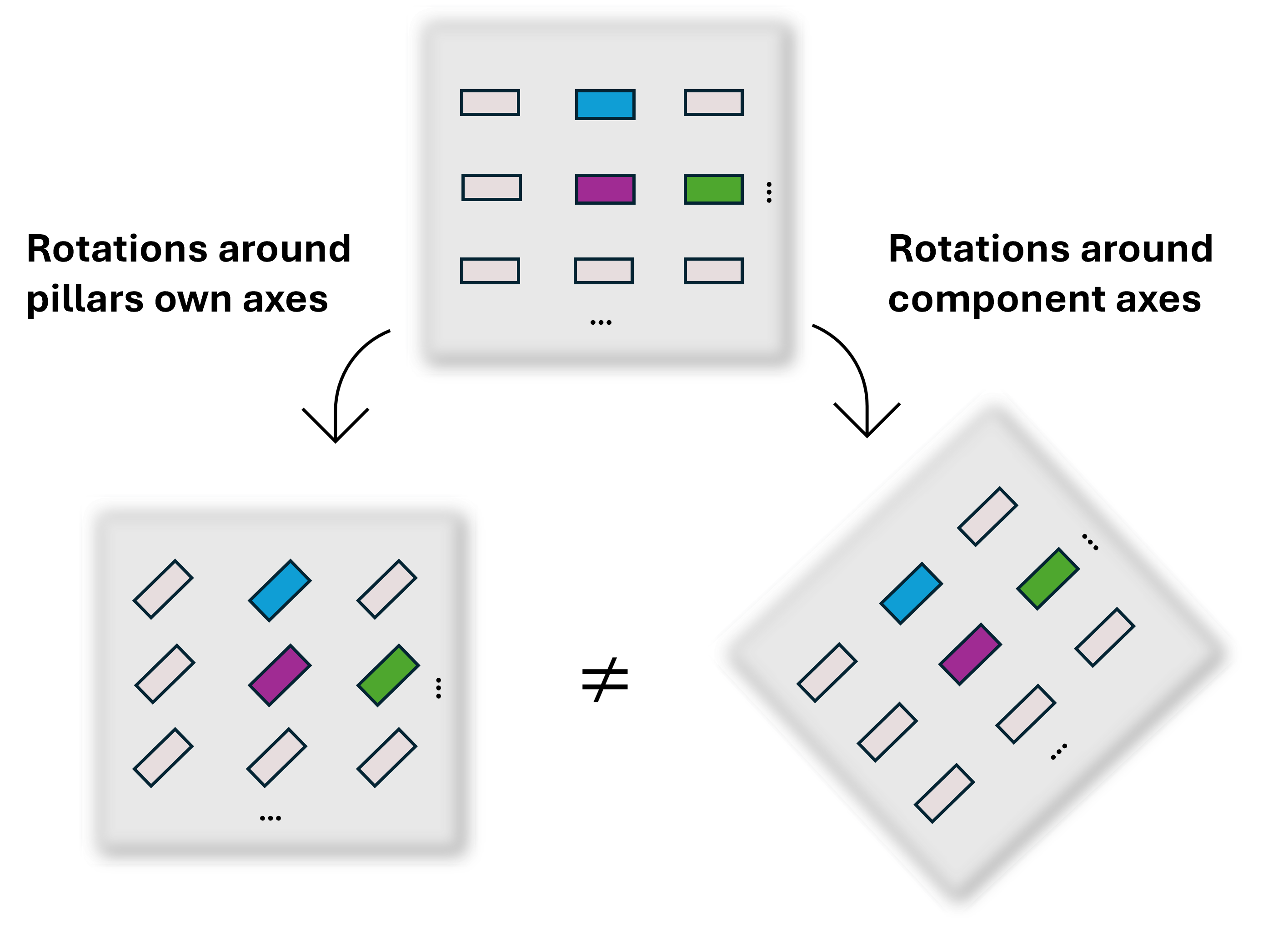
In the first case, represented by equation (2), the arrangement of the scatterers within the metasurface remains the same, as well as the interactions between adjacent meta-atoms. As a consequence, the value of the cost function is not affected by this type of pillar rotation. At the opposite, when considering the rotation of all pillars around their own axes, the spacing between adjacent pillars is slightly affected, as shown in Fig. 3(b), leading to a variation of . The half-wave plate behavior optimized for a rotation angle of is slightly deteriorated by this second type of pillar rotation and the value of the cost function increases accordingly, as shown in Fig.4.
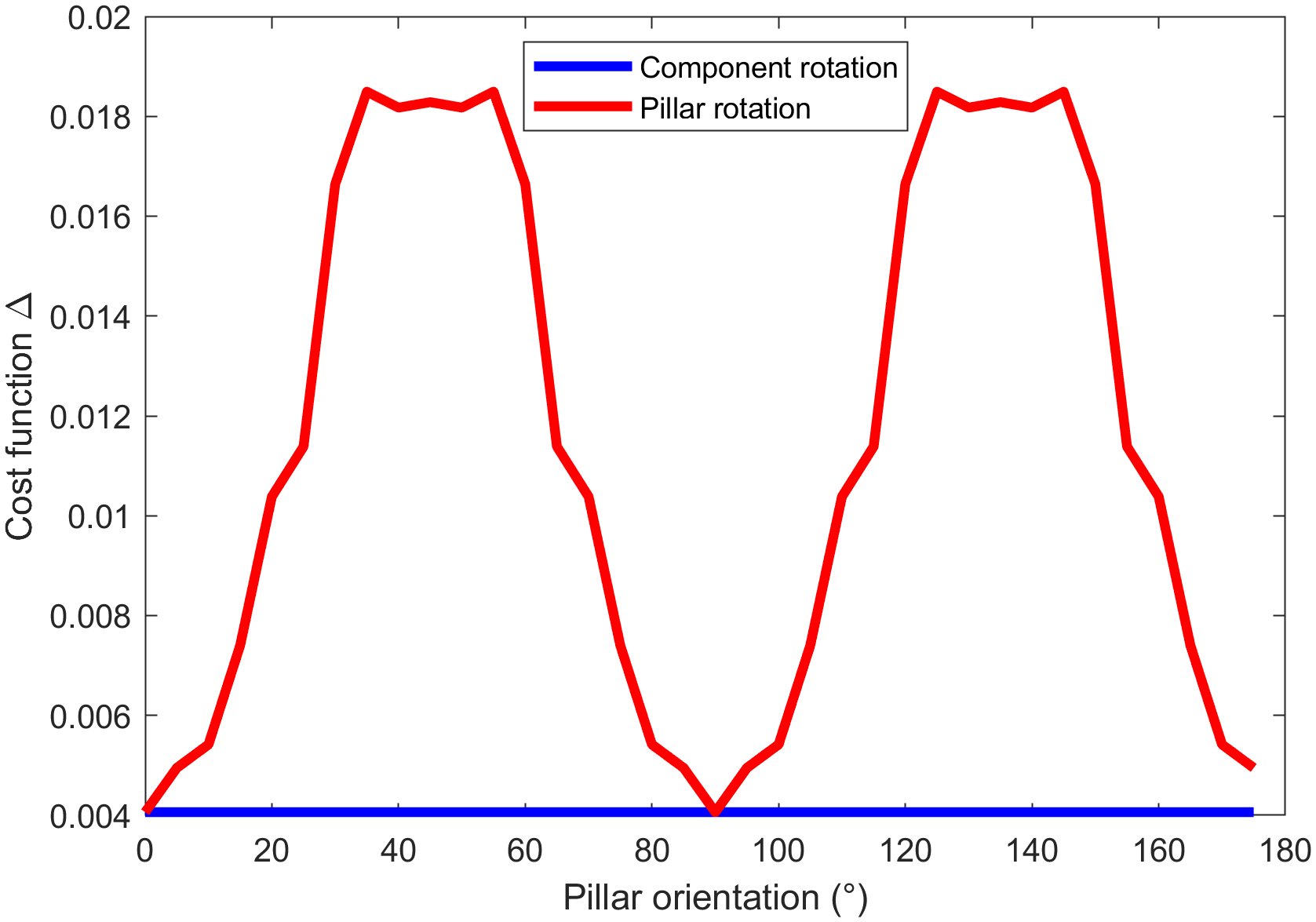
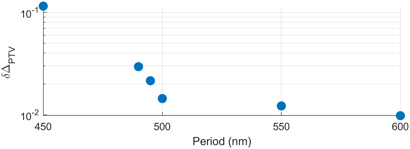
Obviously, the closer the distance between neighboring pillars, the greater this effect. Fig.5 shows the variation of , i.e. the peak-to-valley variation in the behavior that occurs when the pillar is rotated, as a function of the grating period. This quantity increases significantly when reducing the period, leading to a greater loss of the half-wave plate behavior as the pillar rotates. These variations in the behavior when the pillars are rotated remain small and are usually neglected. However, since our application requires high-precision calculation of the DoP, which is a very sensitive parameter, we will thus not use (2) to model rotated pillars. Instead, we will use the RCWA solver to directly model infinite arrays of rotated pillars, and retrieve the Jones matrices corresponding to pillars rotated around their own axes for each angle considered.
The global response of the metasurface is then built by combining the local contributions of every pillar, each of them locally represented by the Jones matrix corresponding to their orientation angle. By doing so, we model the rotations of the pillars around their own axes, but their contributions are considered local and any coupling between adjacent pillars with different orientation angles is neglected.
4 Scrambling Function Implementation
Spatial depolarization is defined by the reduction of the integrated Degree of Polarization (DoPΩ), written as[18]
| (3) |
where is the integral of the Stokes parameters over the spatial domain corresponding to the metasurface dimensions. To ensure spatial depolarization, we need to be as close to 0 as possible.
This is achieved by building a metasurface with pillars having the optimized shape described in Section 2 but varying orientations , as shown is Fig.3(a). In the same way as a half-wave plate would, pillars will locally rotate the polarization state by an angle of , being the pillar orientation angle. For a same incident polarization state, pillars with different orientation angle will produce different output polarization states. The distribution of pillars orientation over the metasurface must then be chosen so the spatial integration of all the local output states gives a minimized DoPΩ. In addition to depolarization performance, the choice of orientation distribution must also be dictated by the reduction of the image degradation induced by the designed component. The formalism used to account for image degradation is described in the next section.
5 Taking Image Degradation into Account
5.1 Fourier Matrix Formalism
To evaluate the impact of the designed metasurface on the image quality, we compute the resulting PSF of a perfect optical system with our device at the entrance pupil. However, there are a number of considerations that need to be taken into account when considering a beam with spatially varying polarization states. As in the case of our metasurface design, the polarization states vary from pillar to pillar across the component, generating an output beam with spatially varying polarization states, making the usual scalar formalism unsuitable. These polarization variations can be accounted for by using a vectorial extension of diffraction theory known as the Fourrier matrix formalism[9]. The idea is to represent the metasurface by a 2x2 Jones matrix varying in space and called the Jones pupil. The four components of represent scalar functions that can be treated individually with diffraction theory, the resulting matrix is called the amplitude response matrix (ARM) and is defined by
| (4) |
where is a 2D spatial Fourier transform. The resulting PSF is calculated by combining the elements of the ARM taking into account the type of illumination (polarized, partially polarized, or unpolarized) and by calculating the square modulus of the result.[19] For example, if the illumination is unpolarized, the PSF of the system is given by a summation of the four elementary PSFs, i.e.
| (5) |
Since the components of are complex quantities, it is interesting to note that spatial linear variations in their phase induce a positional shift of their contribution to the PSF [19].
5.2 Random Pillar Orientation
An intuitive way to scramble the polarization states is to randomly distribute the pillar orientations over the metasurface. Each pillar will have a different orientation angle , randomly chosen between and , as shown in Fig.6(a). Pillars with different orientations will generate a variety of different local polarization states, randomly organized over the metasurface.
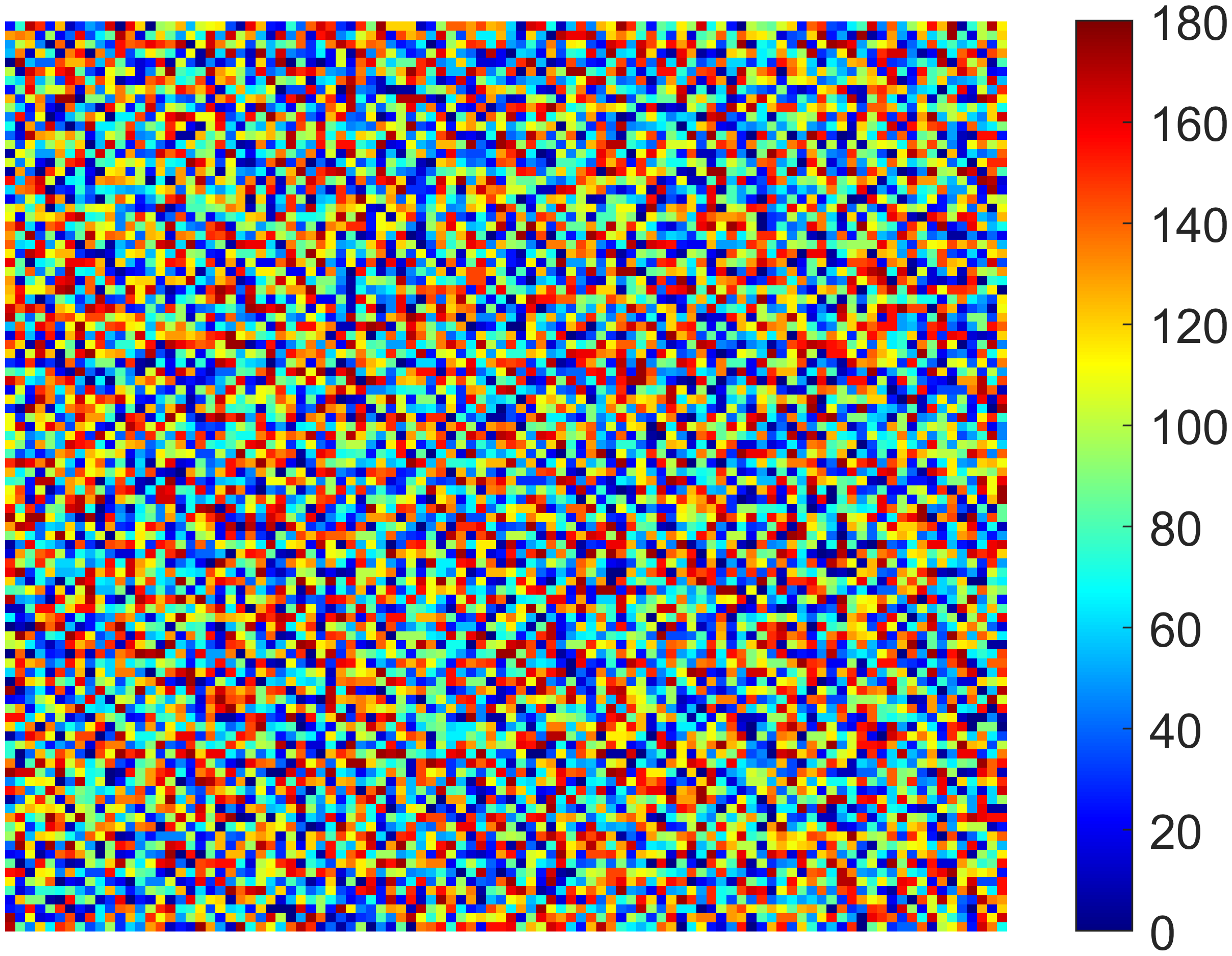
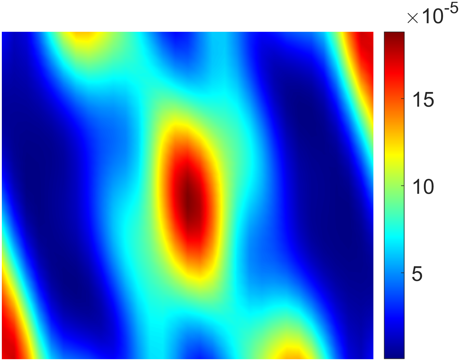
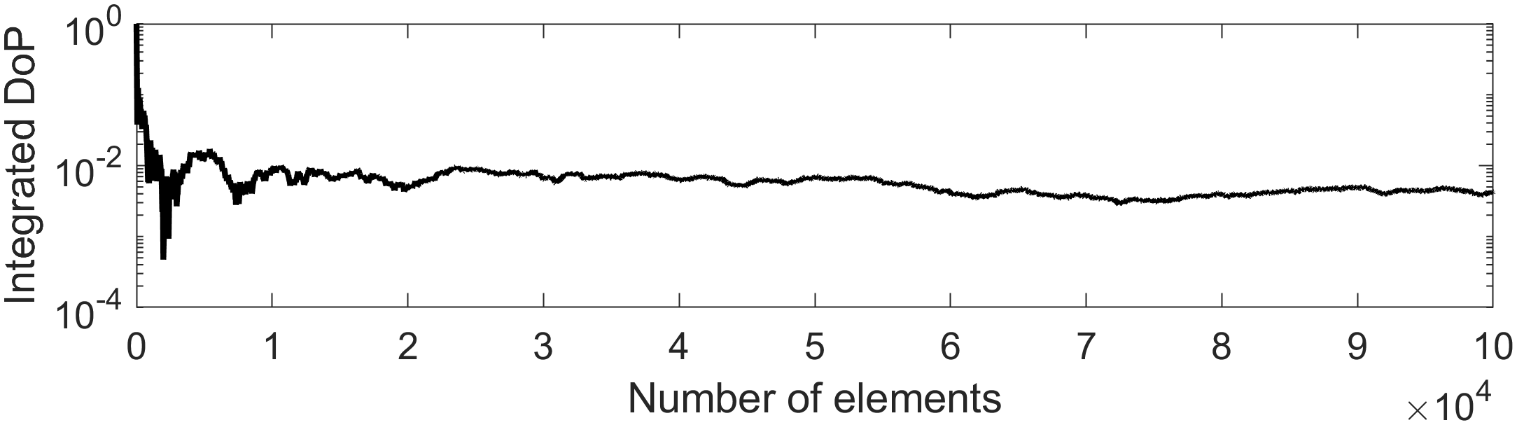
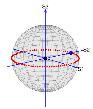
Possible local output states are represented on the Poincaré sphere in Fig.6(d), they are close to the equator thanks to the half-wave plate behavior of the pillars. The barycenter of these points, which represents the spatial integration of the different local states, is very close to the center of the sphere, indicating the depolarizing properties of the device. If we consider a metasurface of dimensions with a pillar periodicity of µm, it represents approximately 1 billion pillars, making this random distribution very efficient in terms of depolarization performance. However, this random organization has a terrible impact on the image quality and turns the PSF into a white noise pattern, as shown in Fig.6(b), where the intensity scale must be noted. As our study focuses on imaging applications, a better trade-off between depolarization and image quality needs to be investigated.
5.3 Linearly Varying Orientation
As mentioned in the previous section, in addition to scrambling performance, we want our component to have as little impact as possible on the image quality of the system. A major problem with prism-based scramblers is their detrimental effect on image quality. The PSF of systems using this type of scrambler is altered by the so-called "diamond effect" [2], which splits the PSF into multiple spots on the detector. It is therefore important to design a polarization scrambling metasurface that reduces this parasitic effect.
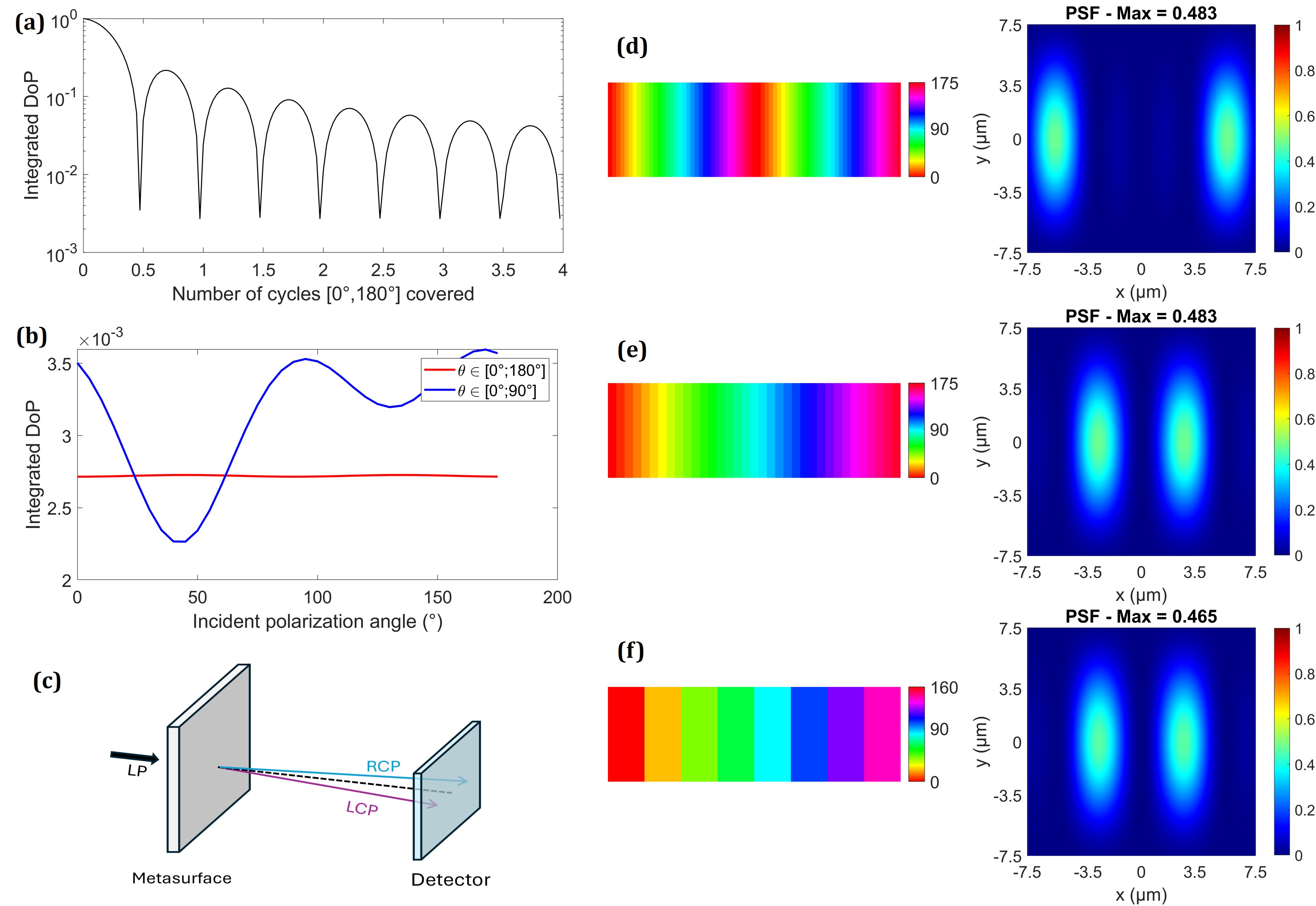
Distribution of the pillar orientation in degrees across the metasurface dimensions (17mm x 5.5mm) and the corresponding PSF at nm: (d) = , , (e) = , and (f) = , .
A possible solution is to use pillars with linearly varying orientations on one direction of the metasurface. However, due to fabrication constraints, the variation of the pillars orientations can not be continuous, we need to consider an orientation step . The metasurface is divided into vertical strips where all pillars have identical orientations, as represented in Fig. 7. The orientation step is the difference in orientation between pillars of adjacent strips. The total coverage represents the range of pillar orientations across the component. Fig. 7a shows that DoPΩ is minimized when this total coverage contains a whole number of cycles . However, as pillars are not perfect half-wave plates, it is best to consider a whole number of cycles to ensure stable scrambling performance regardless of the direction of incident polarization (Fig. 7b).
Figures 7d, 7e, and 7f show different distributions of the orientations of the pillars and the corresponding PSFs at nm. Using linear variation of the pillars orientation has the effect of applying opposite phase slopes to right and left circular polarizations[14], resulting in the division of this PSF into two spots of equal intensities, corresponding to the circular components of the incident linearly polarized beam, as illustrated in Fig. 7c. Since the phase slopes are applied to circular polarization, this division into 2 spots remains the same for any linear polarization at the input. The energy barycenter is located at the center of the detector regardless of the incident polarization direction.
The distance between the 2 spots of the resulting PSF is defined by the phase slope induced by the metasurface. The induced phase slope is directly affected by the number of cycles covered. For components of the same dimensions, the more cycles there are in the pupil width, the greater the applied phase slope, resulting in a greater distance between the two spots, as shown in Fig. 7d. The optimal configuration with the 2 spots as close together as possible is shown in fig. 7e and is obtained by covering only 1 cycle over the metasurface. The phase slope applied by the metasurface also depends on the device dimensions. By using a larger component, we reduce the generated phase slope and thus the spacing between the 2 spots. In our case, we want the global dimensions of the metasurface to match those of the Microcarb pupil, i.e. 17mm x 5.5mm, which explains the elongated shape of the resulting PSF.
Although our solution produces a PSF divided into 2 spots, the distance between them is relatively small and can be expressed in terms of the wavelength , the focal length , the device width , and the number of cycles covered as follows
| (6) |
The PSFs shown in Fig.7 are obtained with numerical simulations using the real parameters of the MicroCarb instrument ( = 17mm and = 63mm), and the spots spacing obtained with the configuration shown in Fig.7e is much smaller than the pixel size of this instrument (15µm). Traditional Dual-Babinet scramblers used in many applications divide the PSF up to 4 spots spread over several pixels of the detector[2]. Our solution therefore reduces the number of spots on the detector, as well as their spacing, and stabilizes the energy barycenter, which are already significant improvements over the diamond effect induced by prism-based scramblers[2].
Figures 7e and 7f show the influence of the orientation step and illustrate that a smaller allows to reduce the losses and to obtain a brighter PSF. The optimal configuration used for the rest of this study is the one represented in Fig. 7e, where the pillar orientations cover only 1 cycle across the metasurface, with an orientation step of .
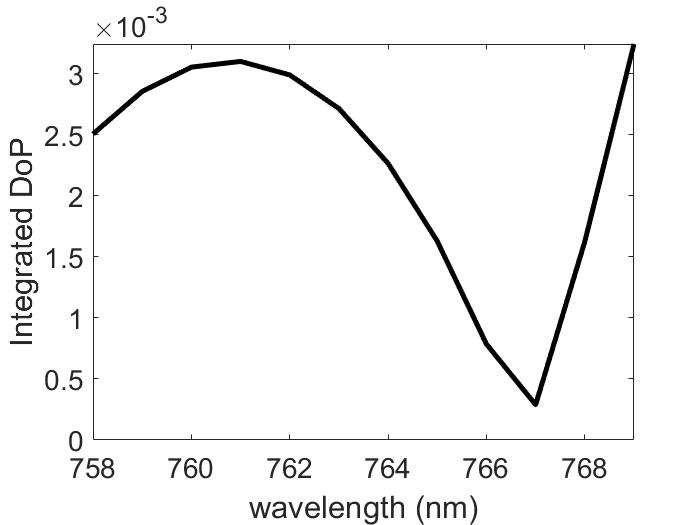
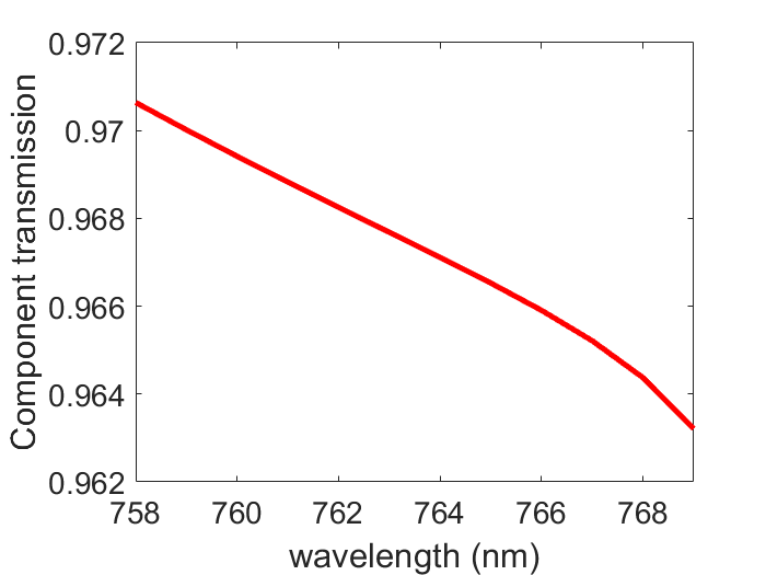
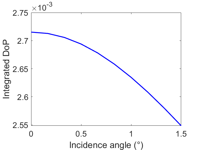
Fig.8(a) shows the wavelength dependence of the simulated integrated DoP obtained with this configuration over the entire B1 waveband of the Microcarb instrument[15]. When considering a 100 linearly polarized input beam, the global transmission is greater than 96 and the resulting output DoPΔΩ remains below over the entire band, indicating spatially depolarized light and validating this first proof of concept. This performance is also maintained when oblique incidence is considered, as shown in Fig.8(c). We limited our analysis to the Microcarb field of view, which is less than in the instrument pupil.
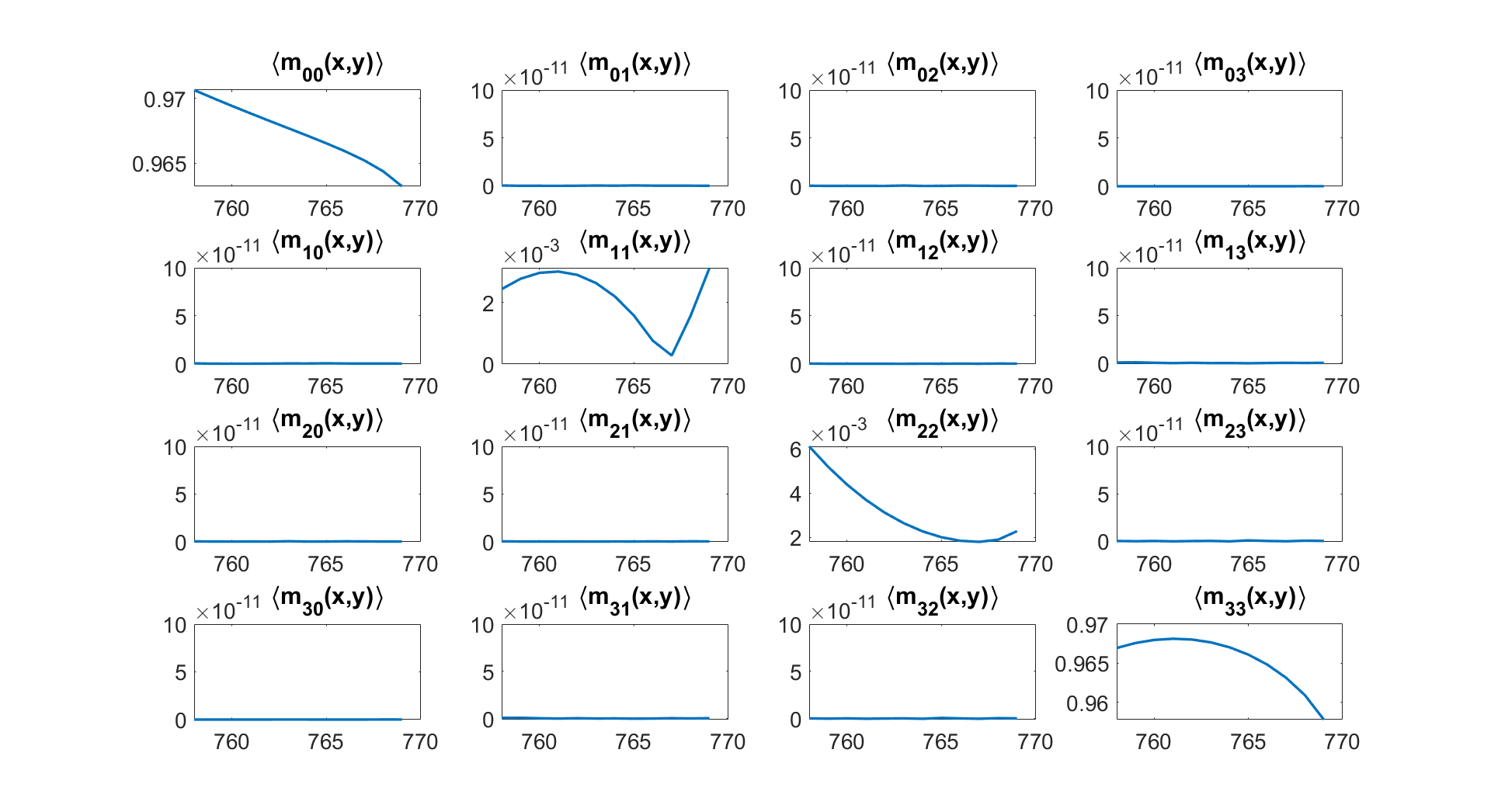
It is also common to represent the polarization scrambler by a x Mueller matrix. In our case, the elements are varying in space from pillar to pillar, Fig.9 shows the spatial integration of this matrix over the metasurface dimensions. As required for a depolarizing device, the integrated Mueller matrix is diagonal, with depolarizing capabilities quantified by the reduction of the diagonal coefficients ,, and . Since our goal was to depolarize only linearly polarized light, the coefficient , which indicates the depolarization of circularly polarized light, does not need to be minimized. The global transmittance is represented by the value of , which is very close to 1 over the entire Microcarb B1 band.
We have demonstrated that spatial depolarization can be achieved with the proposed design. The depolarization performance can be extended beyond the wavelength used for pillar shape optimization (here nm) to obtain good depolarization capabilities over a spectral bandwidth, which may correspond to a realistic band used in space missions, as shown in Fig.8(a). However, spectral limitation is still an issue, and performance drops when we deviate too far from the design wavelength. The optimization strategy used in this proof of concept is quite simple, and a more advanced multi-wavelength optimization process may help to find parameters that allow the integrated DoPΩ to remain more stable with respect to wavelength and/or angle of incidence variations.
6 Application to the MicroCarb instrument
MicroCarb is a space instrument led by the French space agency CNES with the aim of accurately monitoring the concentration of green gas in the atmosphere.[15] The optical design of the instrument includes a Dual-Babinet polarization scrambler [2] operating in 4 different wavebands, listed in Table 1. We have shown that our scrambling solution reduces the image degradation associated with the depolarization process compared to Dual-Babinet scramblers, by reducing the number of spots and their spacing.
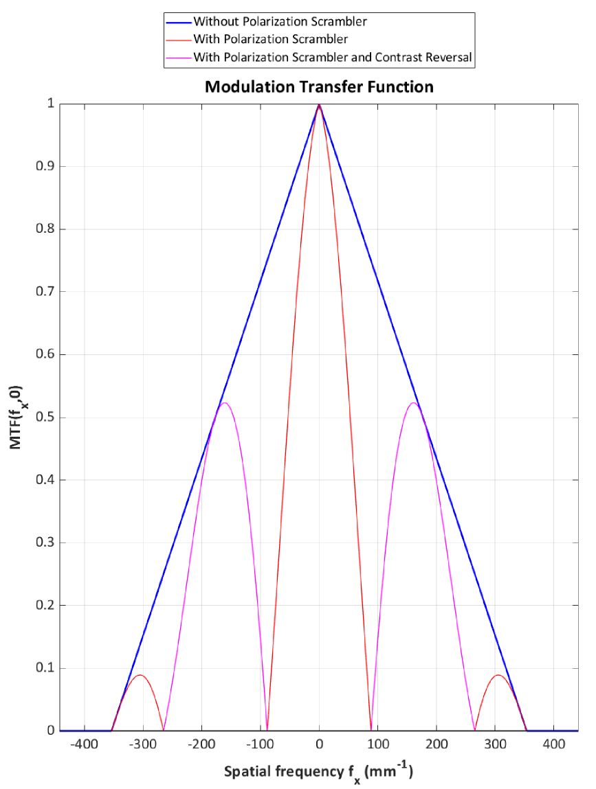
However, we have not analyzed the impact of the introduction of this polarization scrambler on the image quality of the MicroCarb instrument, when the reference situation corresponds to one in which the optical design does not include Babinet prisms and is free of aberrations. To perform such a system-level analysis, we have chosen to use the modulation transfer function (MTF) as a key parameter. The PSFs of the instrument shown in Fig. 8(d) to (f) can be described as a first approximation by the following equation
| (7) |
where (or ) is the width of the pupil along the (or ) direction, is the focal length (here, 63 mm), is the wavelength, and is the distance between the two spots, as defined by (6).
It is easy to show that the MTF corresponding to this PSF is given by [20]
| (8) |
where and are the spatial frequencies associated with the and coordinates, and Tri is the triangular function defined by
| (9) |
With respect to the reference situation, described by the product of the two triangular functions, the effect of the polarization scrambler is the adding of the cosine term. The presence of this new term will essentially modify the MTF along the axis, as shown in Fig. 10, introducing periodic degradation with contrast reversal (the part of the curve in magenta). At the spatial frequency corresponding to the MicroCarb pixel size ( µm, i.e. 67 mm-1), the MTF drops from 81% to 31%. A good solution might be to adjust the focal length and/or the pixel size to reach the working point corresponding to a phase value for the cosine term (MTF about 50%).
Figure 8(a) shows that we can achieve good depolarization performances over the B1 band of MicroCarb, however the performance collapses when we deviate too much from the wavelength used for pillar shape optimization. Therefore, we need to adapt our design to work on the 4 different wavebands of the instrument.
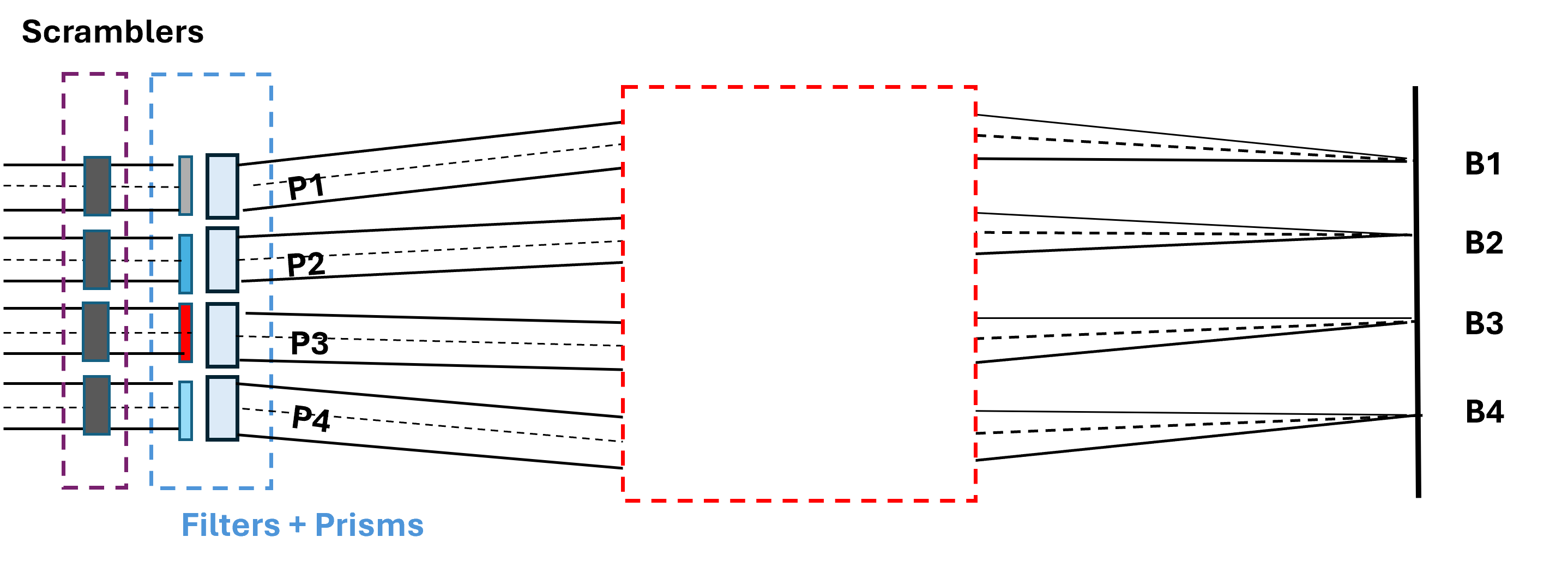
Although MicroCarb actually uses 4 wavebands, they propagate in parallel. They are separated from each other by filters, each of which passes through a dedicated sub-pupil[15]. We can therefore achieve spatial depolarization for the 4 bands by building 4 sub-scramblers, each optimized for a specific band and placed in front of the corresponding sub-pupil, as shown in Fig.11. An even more compact system could be envisioned using the same substrate for both filters and metasurface scramblers.
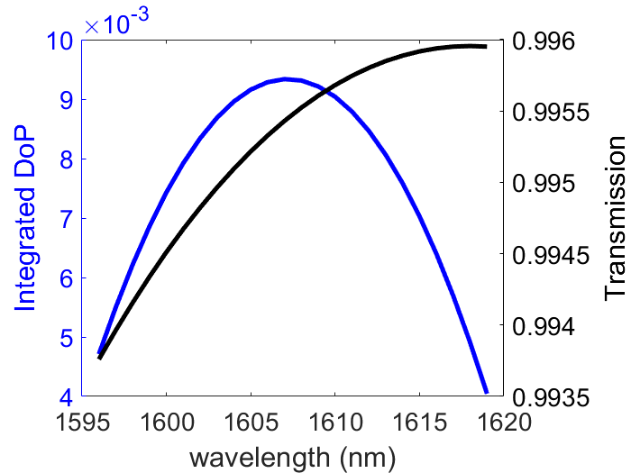
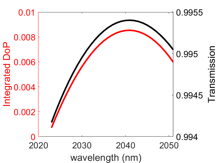
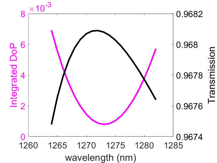
The same optimization process as described in Section 2 is applied to the Microcarb B2, B3 and B4 wavebands. For each channel, we found geometric parameters that allow the metasurface unit cell to behave as a half-wave plate, i.e. minimize . Unit cell parameters and depolarization performance optimized for B2, B3 and B4 are shown in Table 1 and Figs. 12(a), 12(b) and 12(c). Pillar material was changed to Si for these wavebands to ensure good transmission in the IR. As for B1, the optimization strategy used to define the unit cell parameters remained very simple, focusing on only 2 parameters and .
| Band | Bandwidth | Materials | ||||
|---|---|---|---|---|---|---|
| B1 | 758 nm - 769nm | TiO2/SiO2 | 106 nm | 288 nm | 500 nm | 1000 nm |
| B2 | 1596 nm - 1619 nm | Si/SiO2 | 218 nm | 400 nm | 800 nm | 1000 nm |
| B3 | 2023 nm - 2051 nm | Si/SiO2 | 269 nm | 529 nm | 1000 nm | 1200 nm |
| B4 | 1264 nm - 1282 nm | Si/SiO2 | 141 nm | 313 nm | 650 nm | 1100 nm |
7 Conclusion
We have designed a novel polarization scrambler based on the use of a metasurface. We used anisotropic dielectric scatterers with optimized dimensions to act as half-wave plates and rotate linear polarization states. By distributing these scatterers with linearly varying orientation across the width of our device, we are able to generate multiple local polarization states for which the integrated DoP is minimized. We have evaluated the performance of our design in terms of depolarization and impact on the PSF. Our device is able to both minimize the integrated DoP and reduce the impact on the system image quality, while providing a compactness advantage over prism-based scramblers. Although we have used simple optimization strategies, the depolarization capabilities obtained at one wavelength can be extended to the entire B1 waveband of the MicroCarb instrument. By adjusting the parameters of our design, it is possible to build scramblers that operate at other wavebands, allowing this type of depolarizer to be used over the entire operating range of instruments such as the MicroCarb. Performance could be further improved by using more advanced optimization of the unit cell, but this work already opens up promising opportunities for developing more efficient scrambling solutions using metasurfaces. Investigations are currently underway to produce a full-size prototype to match the Microcarb pupil size, i.e. 17mm x 5.5mm. Comparing the experimental results with the numerical expectations presented above is the next step in this work.
Funding This work has been achieved thanks to the support of the French Centre National d’Etudes Spatiales - CNES, and the company CILAS in the context of the joint laboratory LabTOP. \bmsectionDisclosures The authors declare no conflicts of interest. \bmsectionData availability Data underlying the results presented in this paper are not publicly available at this time but may be obtained from the authors upon reasonable request.
References
- [1] A. P. Loeber, “Depolarization of white light by a birefringent crystal. II. The Lyot depolarizer,” \JournalTitleJournal of the Optical Society of America 72, 650–656 (1982).
- [2] J. Loesel, M. Dubreuil, V. Pascal, et al., “Microcarb polarization scrambler,” in International Conference on Space Optics — ICSO 2014, vol. 10563 B. Cugny, Z. Sodnik, and N. Karafolas, eds. (SPIE, 2018), p. 1056318.
- [3] J.-L. Bézy, G. Bazalgette, B. Sierk, et al., “Polarization scramblers in Earth observing spectrometers: lessons learned from Sentinel-4 and 5 phases A/B1,” in International Conference on Space Optics — ICSO 2012, vol. 10564 E. Armandillo, N. Karafolas, and B. Cugny, eds. (SPIE, 2017), p. 105642B.
- [4] R. A. Chipman, “Analysis of spatial pseudodepolarizers in imaging systems,” \JournalTitleOptical Engineering 29, 1478 (1990).
- [5] P. Genevet, F. Capasso, F. Aieta, et al., “Recent advances in planar optics: from plasmonic to dielectric metasurfaces,” \JournalTitleOptica 4, 139 (2017).
- [6] M. Khorasaninejad, W. T. Chen, R. C. Devlin, et al., “Metalenses at visible wavelengths: Diffraction-limited focusing and subwavelength resolution imaging,” \JournalTitleScience 352, 1190–1194 (2016).
- [7] W. T. Chen, A. Y. Zhu, J. Sisler, et al., “A broadband achromatic polarization-insensitive metalens consisting of anisotropic nanostructures,” \JournalTitleNature Communications 10, 355 (2019).
- [8] J. Billuart, S. Héron, B. Loiseaux, et al., “Towards a metasurface adapted to hyperspectral imaging applications: from subwavelength design to definition of optical properties,” \JournalTitleOptics Express 29, 32764 (2021).
- [9] N. A. Rubin, G. D’Aversa, P. Chevalier, et al., “Matrix Fourier optics enables a compact full-Stokes polarization camera,” \JournalTitleScience 365, eaax1839 (2019).
- [10] Y. Hu, X. Wang, X. Luo, et al., “All-dielectric metasurfaces for polarization manipulation: principles and emerging applications,” \JournalTitleNanophotonics 9, 3755–3780 (2020).
- [11] K. Jie, H. Huang, S. Qin, et al., “Electronically Controlled Time-Domain Integral Average Depolarizer Based on a Barium Titanate (BTO) Metasurface,” \JournalTitleNanomaterials 12, 1228 (2022).
- [12] P. Schau, L. Fu, K. Frenner, et al., “Polarization scramblers with plasmonic meander-type metamaterials,” \JournalTitleOptics Express 20, 22700 (2012).
- [13] Y. Wang, W. Zhu, C. Zhang, et al., “Ultra-compact visible light depolarizer based on dielectric metasurface,” \JournalTitleApplied Physics Letters 116, 051103 (2020).
- [14] J. Balthasar Mueller, N. A. Rubin, R. C. Devlin, et al., “Metasurface Polarization Optics: Independent Phase Control of Arbitrary Orthogonal States of Polarization,” \JournalTitlePhysical Review Letters 118, 113901 (2017).
- [15] F. Pasternak, L. Georges, V. Pascal, and P. Bernard, “The microcarb instrument,” in International Conference on Space Optics — ICSO 2016, vol. 10562 N. Karafolas, B. Cugny, and Z. Sodnik, eds. (SPIE, 2017), p. 105621P.
- [16] N. A. Rubin, Z. Shi, and F. Capasso, “Polarization in diffractive optics and metasurfaces,” \JournalTitleAdvances in Optics and Photonics 13, 836 (2021).
- [17] A. Arbabi, Y. Horie, M. Bagheri, and A. Faraon, “Dielectric Metasurfaces for Complete Control of Phase and Polarization with Subwavelength Spatial Resolution and High Transmission,” \JournalTitleNature Nanotechnology 10, 937–943 (2015).
- [18] S. Huard, Polarisation de la lumière (Masson, 1994).
- [19] J. B. Breckinridge, W. S. T. Lam, and R. A. Chipman, “Polarization Aberrations in Astronomical Telescopes: The Point Spread Function,” \JournalTitlePublications of the Astronomical Society of the Pacific 127, 445–468 (2015).
- [20] M. Lequime and C. Amra, De l’Optique électromagnétique à l’Interférométrie : Concepts et Illustrations (EDP Sciences, 2013).