Gas-cell development for nuclear astrophysics motivated studies on noble gas targets and the 3He(,)7Be reaction
Abstract
In classical nuclear physics experiments a particle beam impinges on a target containing the nuclei of the other reactant. In most cases the target is solid, either in atomic or in molecular form. However, there are selected cases, where solid target is hardly be produced. Such a case is in particular, when the target is noble gas. In many astrophysical scenarios, such as big bang nucleosynthesis (BBN), stellar hydrogen burning, and supernova explosions, alpha induced reactions on noble gas nuclei play a crucial role. Studying these reactions in the laboratory requires these noble gas atoms to be confined in a sufficient amount to allow the reactions.
For example, in case of the 3He(,)7Be reaction, both reactants are noble gases. This reaction plays an important role both in the solar pp-chains and in BBN. The reaction cross section was experimentally determined in several works, however there are still energy regions lacking experimental data, rendering the extrapolations towards the astrophysically relevant energies uncertain.
To be able to study among others the 3He(,)7Be reaction, a thin-windowed gas-cell target was developed, which can be used to study alpha induced reactions on noble gases leading to radioactive isotopes.
If the reaction product is radioactive with a suitable half-life, it is collected inside a catcher foil to be analyzed later with gamma spectroscopy.
Using the described gas-cell, new experimental total cross section of the 3He(,)7Be reaction was determined in the energy range of keV. These results confirm the overall trend, and also the absolute scale set by the only one previous measurement in this energy range. Furthermore, a selection of nuclear astrophysics motivated activation reaction studies are presented where gas-cell target was already successfully used.
In addition, studying particle scattering with the same reactant as a radiative capture gives valuable information about the compound nucleus. The measured scattering cross section can be directly used in the extrapolations or validations of theoretical reaction cross section estimates. For this aim, gas-cell was designed to study alpha scattering on noble gas target. A few pilot measurement is presented with the scattering gas-cell.
1 Introduction
Noble gas targets are highly important in astrophysics motivated nuclear experiments. In several astrophysical scenarios, both of the reaction partners are noble gas nucleus. For example, the 3He(,)7Be reaction is important both in the big bang nucleosynthesis (BBN) Fields11-ARNPS and in the solar pp-chains Acharya24-arxiv . In case of the heavy element synthesis, large reaction networks have to be considered, for which the rates are usually derived from theoretical cross section calculations, mainly using the Hauser-Feshbach (H-F) statistical model Hauser52-PR . Experiments on proton and alpha induced reactions are important to pin down the model parameters. In many cases, reactions on noble gas isotopes have key importance in these parameter determinations. As an example, the 124Xe(,)128Ba reaction is a key reaction in the p-process reaction network Rauscher06-PRC ; Rapp06-AJ , while 86Kr(,n)89Sr is important in the weak r-process Bliss20-PRC ; Psaltis22-AJ .
If proton induced reactions are considered, the limitations of a noble gas target may be mitigated with inverse kinematic studies, where the heavier noble gas reactant is the beam impinging on hydrogen containing target. However, in case of alpha induced reactions, both of the reaction partners are noble gases, thus exchanging them still not solve the difficulties to obtain noble gas target. In a typical nuclear astrophysics experiment the target needs to have an areal density at least in the order of the atoms/cm2, but in some cases even atoms/cm2 is required. This target thickness is easily achieved with solid state targets, however, noble gases do not form solid compounds. In the same time the targets have to withstand an ion beam bombardment of a few Coulombs with a rate of a few hundreds of nA up to a few tens of A ( particle/s) without major deterioration to obtain measurable reaction rate. In addition, in many cases isotopically enriched material have to be used, which could be quite expensive or simply not available in higher quantities, thus posing a strong constraint on the amount of total material to be used. One way to create solid targets out of noble gases is implantation, when accelerated noble gas atoms impinge on a solid host material, and they trapped in the crystal structure. Both the stability and the achievable thickness of such targets depend heavily on the used host material. Even though the thickness can reach the minimum required atoms/cm2, in many cases – due to the beam induced heat – the noble gas atoms may escape causing deterioration of the target Lhuillier11-JNM . Alternatively, thin targets can be made by sputtering material in noble-gas atmosphere, forming porous films with closed cells containing the gas on the hosts surface. However, the target thickness in these case is usually not sufficient for a typical nuclear astrophysics experiment, and opening the closed cells due to the deposited beam power can cause uncontrolled deterioration Ibrahim24-V . With the use of gas targets in most cases the above limitations can be mitigated, however, the confinement of the gas in the beam-line vacuum while letting the beam interact with it poses its own challenges.
The purpose of this paper is to present the technical development of thin-window gas-cell target systems and their application to the measurement of the 3He(,)7Be reaction cross section. In addition gas-cell target developments towards the measurement of 3He+4He scattering is also shown. The paper is organized as follows: in Sec. 2 general introduction about gas targets are given, in Sec. 3 the general differences in data analysis between experiments on gas-cell target and on solid targets is expressed. In Sec. 4 the design and main parameters of the gas-cells targets are detailed, while in Sec. 5 the new 3He(,)7Be experiment and its results are presented followed by an outlook towards particle scatting studies in Sec. 6. Finally a summary is given in Sec. 7.
2 General properties of gas targets
If the target material has to be used in its gas form, then that shall be confined into a given volume for the beam interaction. There are three ways to achieve this. In the first method the outflow of the gas from the interaction volume is restricted by small apertures while the gas is continuously supplied back in order to compensate the loss (windowless extended gas target). The second option is dynamic confinement where the continuously supplied gas has no time to escape from a restricted volume owing to its high speed (gas jet target), and the third is static confinement with windows (thin windowed gas-cell target). Examples of these options and their main features are follow.
In a windowless extended gas target the gas is flowing out from the confined reaction space through the aperture where the beam enters Ferraro18-EPJA ; Paneru24-PRC . The amount of gas leaking out can be mitigated with long collimators. These shall have large enough diameter for the beam to pass through. Usually, several pumping stages are installed before the target separated by collimators. In each stage towards the accelerator, lower and lower pressures can be achieved, thanks to the high gas-flow impedance of the collimators. The usual beamline vacuum of mbar can be achieved in two or three stages. If the gas is expensive, recirculation is mandatory, which may include a gas purifier for removing any in-leaked contaminants and buffer volume to maintain a steady gas flow. Even if the recirculation saves the precious gas from immediate consumption, a minimum of a few standard liter of gas is necessary. The other windowless option is the so called jet-target Schmidt18-NIMA ; Yadav23-EPJWC . In this case the pressurized target gas is sent through a small nozzle into the vacuum chamber towards a receiver pump, generating a supersonic gas flow. Because of its speed, the gas stream does not spread a lot before it reaches the receiver. The small outflow is usually also captured by staged pumping. Similarly to the previous option, for expensive gases a recirculation is mandatory in most cases complemented by a compressor stage, thus the total amount of the gas in the system is even higher than in case of the windowless extended gas target. The third option is to create a completely sealed volume, where the gas is filled in Bordeanu12-NIMA ; Toth23-PRC . The main advantage of this configuration is the much simpler, thus more cost efficient design, and the much less amount of gas needed in the order of a few hundredths of a standard liter. In this case the main problem is that the beam has to reach the target through some solid material sealing the gas volume. However, as we will see, using thin vacuum tight metal foil windows, this can be achieved. The main disadvantage is the window itself, which may give a rise of beam induced background, and reduces the beam energy and widens the energetic width. However, these can be well handled in many practical cases.
3 Cross section determination with gas-cells
3.1 General considerations
In practical terms, there are only small differences in deriving cross section data from measurements with gas-cell and solid state targets using the activation method. In case of a gas-cell, the number of beam particles can be determined from charge integration identically to a solid target experiment. In our case the complete gas-cell is placed onto an irradiation chamber electrically isolated from the rest of the beamline, acting as a Faraday-cup. In this way, the possible charge exchange processes happening inside the gas or foils do not affect the current reading as opposed to other type of gas targets. The number of target atoms can be derived from the initial pressure, temperature and gas-cell length, using the ideal gas law. Since the gas-cell is sealed, the areal number density of the active target atoms do not change, even if the temperature or pressure changes due to the heating effect of the beam. Gas can desorb from the inner gas-cell surfaces. However, that is either air or water vapor absorbed earlier, when the gas-cell was exposed to the ambient atmosphere. The extra gas may change the effective beam energy and collection efficiency of the reaction products, but does not change the number of active target atoms. Since the reaction products are created almost evenly in the gas volume, those have to reach the catcher and implanted into it. In usual cases, the implantation probability is determined from simulations usually using e.g. GEANT4 Agostinelli03-NIMA ; Allison06-ITNS ; Allison16-NIMA . These simulations also includes the energy loss and stopping of the created recoils in the gas volume, so do the possible backscattering from the catcher. Even if the reaction kinematics is well known and the charged particle transfer simulations are sufficiently reliable, the usual goal is to have better than 80% implantation probability to minimize the uncertainty caused by this effect.
In case of particle scattering with gas-cell, few of the above considerations is not relevant. Since the scattering cross section is usually measured relative to a given angle where the Rutherford cross section dominates. Both the target thickness and target current factors out. Even a slight target loss can be allowed during the measurement, not affecting the data analysis. It is important, however, that the scattered particles have to reach the detectors, and the scattering angle have to be well determined.
3.2 Effect of the energetic beam width
The main difference between a solid target experiment and a gas-cell which shall be considered is the energy loss in the entrance foil and the beam energy spread. The latter includes the initial energetic beam width in addition to the energetic widening caused by beam energy straggling in the foil.
In the case of a negligible energetic beam width, the reaction yield () from a target with energetics thickness of can be calculated as follows Iliadis-book
| (1) |
where is the beam energy at the target surface, while and are the energy dependent cross section and stopping power, respectively. If substantial beam energy spread is present, as it can be in the cases of a thin-windowed gas-cell, the following more general expression shall be used instead Rolfs-book
| (2) |
where is the normalized beam energy distribution. This equation still assumes that the beam energy distribution does not change significantly along the target. In our cases this is true, since the energy loss is small (1%) compared to the beam energy itself. In practical cases, it is sufficient to approximate with a Gaussian function centered at the beam energy , when that enters the active volume, and having a given standard deviation, which in the following will be called as the energetic beam width.
If both and is constant the above equations reduces to the following relation
| (3) |
where is the areal number density of the target atoms, and is the energy at which 50% of the total yield is obtained Iliadis-book . represents a boxcar function with a width of . The integral is apparently the convolution of the beam distribution with the target thickness represented by the boxcar function. Because of the normalization of the functions, the integral is unity, thus the equation reduces to the following standard relation
| (4) |
This is the same as the reduced Eq. (1) under the same assumptions, thus the beam energy spread does not play a role. If inactive atoms are also present in the target, shall be replaced by , the effective stopping power of the active atoms. If the composition changes by introducing inactive material into the target, the target thickness may change, but not the number of active target atoms.
In case of a beam with negligible energy spread, Eq. (4) is valid if the cross sections and the stopping power is slowly varying within the target thickness. A non negligible energy spread do not modify the equation, but makes it valid only if and is slowly varying within the energy range covered by the convolution in Eq. (3). If this criteria is met, the derivation of the cross section from the yield is straightforward. However, if any sharp structure, i.e. a resonance, is present in the cross-section function in this non-negligible energy region, it alters the yield, while without knowing the actual shape of the cross-section function, the ”real” effective energy cannot be exactly determined. In our practical cases the characteristic energy range of any structure in the excitation function is much larger than the range covered by the non-negligible part of the convolution, thus it is sufficient to base the analysis on Eq. (4). However, one shall keep in mind, that if e.g. a yield excess is observed, it is smoothed out by the beam energy spread and the attributed effective energy is not simply the half energetic target thickness, and maybe a resonance have to be accounted for.
Beside the disadvantage of a more complicated data analysis in case of the presence of a resonance, an experiment with a beam of broader energy distribution has its advantage. Recording the excitation function with overlapping energy distributions, sharp resonances cannot be missed, which can be the case with sharp beam energy distribution and data points further separated in energy than the target thickness. If a broader energy range of the excitation function is to be mapped, this latter can be an issue.
3.3 Energy uncertainties with gas-cells
As mentioned in the previous section, the main difference between a solid target investigation and a gas-cell measurement is the beam energy loss and straggling in the entrance foil. The energy uncertainty posed by these effects will be discussed here.
In our experiments, the precise thickness of the entrance window is measured by placing the foils in a dedicated setup consisting of a triple-nuclide -source and a particle detector. The energy loss of the -particles penetrating the foils was used for the thickness determination. The exact procedure is detailed in Ref. Szucs19-PRC . This method allows to measure the entrance foil thickness with precision of better than 1% – excluding the stopping power uncertainty, which is introduced later in the calculation. With the precise knowledge of the entrance window thickness, the beam energy loss and straggling is calculated using the SRIM charged particle transport code Ziegler10-NIMB .
The uncertainty of the energy loss can be decomposed into two parts, first the foil thickness uncertainty and then that of the stopping power. These two shall be treated separately, since the first contributes to the point-by-point (p.b.p.) energy uncertainty, while the latter to the systematic (syst.) energy uncertainty.
The p.b.p energy uncertainty is composed form the following: the initial beam energy uncertainty, which is limited by the precision of the acceleration and beam transport (magnetic fields, geometries of the magnets and beam defining apertures), is an inherent quantity for a given irradiation station. This is the limit at each irradiation energy, on how precisely the beam energy can be set, and this uncertainty has to be taken into account also for solid target experiments. Additionally, in case of the gas-cell experiments, the entrance foil thickness uncertainty of less than 1% has its contribution to the interaction energy uncertainty. If the energy loss is not more than a few tens of a percent of the initial beam energy, this causes only a few tenth of a percent additional p.b.p. energy uncertainty.
The other part of the energy loss uncertainty is the stopping power uncertainty, which affects systematically the energy of the whole dataset, thus may shift the energies of the whole dataset together. The stopping power uncertainty entering into the foil thickness determination is considered here. If the actual reaction measurement utilizes other beam particle than , than the uncertainty of the stopping power of that shall also be considered in addition.
In principle, the beam energy loss in the gas (and not only in the entrance foil) would also have a point-by-point and a systematic uncertainty on the reaction energy. However, the overall small energy loss in the gas (few tens of keV) compared to the initial beam energy (few MeV) renders it negligible. For the same reasons, the target thickness affects the effective energy, but only negligibly its uncertainty.
4 Development of the gas-cell target designs and their application
In recent years, several editions of gas-cells were produced in Atomki, Debrecen, Hungary. Most of them were successfully utilized in activation experiments Bordeanu12-NIMA ; Toth23-PRC ; Szucs19-PRC ; Bordeanu13-NPA ; Halasz16-PRC ; Szegedi19-NPA ; Kovacs25-NIMA , while their designs were fine tuned for given purposes. The goal were to find suitable foils closing the gas volume, while withstand the pressure difference and the heating effect of the beam. Depending on the target gas both the target pressure and selected beam energies cover a broad range. In addition, the purity of the catcher foil was also crucial to avoid parasitic activity creation. The summary and comparison of the main parameters of the different gas-cell setups are shown in Table 2, while details of them is presented in the following section.
Beside the gas-cell used for activation, that for particle scattering experiments was also under development. In this case the main goal was to find the most suitable gas-cell and detector geometry allowing the detection of the scattered particles from the gas, while those from the entrance foil was suppressed.
4.1 One windowed activation gas-cells (#1 and #2)
The gas-cell was originally designed to measure both 3He(,)7Be and induced reactions on 124Xe. Its performance was already presented in Ref. Bordeanu12-NIMA , its design drawing is shown here in Fig. 1. About its design features only a brief summary is given here.
For gas-cell design #1 the entrance window was 1-m-thick nickel foil glued on a stainless steel frame with an 8-mm-diameter opening. The outer part of the frame was pushing against an o-ring, sealing the gas volume from the beam-line vacuum. In this case the catcher (used to collect the radioactive reaction products, see below) was directly placed onto the water-cooled beam stop inside the gas-cell volume. The complete beam stop was removable. Another o-ring sealed the rear part of the gas-cell from the outside atmosphere. A thick high purity copper disk was placed and secured with screws onto the water cooling, which stopped the beam and collected the reaction products. With this gas-cell the cross section of 3He(,)7Be was successfully measured in the beam energy range of MeV using about 300 mbar target gas pressure corresponding to about atoms/cm2 Bordeanu13-NPA .
Cell design #2 was used for 124Xe irradiations with higher beam energies ( MeV). This higher energies called for different foils. The thin vacuum tight nickel entrance foil was not any more available. It was replaced by the thinnest commercially available vacuum tight Al foils (6.5-m thick). It caused a beam energy loss twice as much as the 1-m Ni foil, however, it was still acceptable because of the higher beam energies. The copper catcher was not suitable any more, since longer lived (more than a few minutes in this case) activity could have been created in it via (,n) reactions. A thinner catcher of 20-m Al was chosen, because irradiation do not create longer lived activity in aluminum. In addition, this thickness made it possible to deposit most of the beam power directly in the tantalum lined beam stop. However, still about 20% of the beam power heated the catcher foil. The lower mass number of the catcher facilitated also the implantation of the reaction products. Because of the heavy target nuclei, the recoils from the reaction had only -keV kinetic energy uniformly distributed in the 50 mbar 124Xe gas volume, which corresponded to about atoms/cm2 target thickness. As a result, only those recoils were implanted into the catcher which were created in the last 1-2 mm of the target, the others were stopped by the gas. The implantation depth was only nm into the catcher foil, which may also resulted in collection loss, if the already implanted atoms diffuse out.

In addition, a constant pressure increase was observed during each irradiation. A typical case is shown in Fig. 2, where the initial 55 mbar pressure increased to 90 mbar during the 15-h-long irradiation. The rate of the pressure increase is in correlation with the beam current. A small instantaneous pressure change about 0.5 mbar occurred when the beam was switched on or off. This increase or decrease can be clearly seen at the beginning where after a two minute irradiation the beam was stopped for a few minutes and restarted again. Then around the 7th hour, the beam was lost again. Since in that case the current decreased continuously within half an hour, the down-jump is not prominent. However, when the beam was instantly regained, the up jump is visible. Finally, switching off the beam caused a down jump. These jumps are attributed to the sudden gas temperature changes. The beam constantly deposits energy inside the gas volume, while the gas is cooled by the approximately constant temperature gas-cell walls. An equilibrium in temperature is quickly achieved after the power source (the beam energy deposition) changes. A particle detector was placed in the chamber detecting the backscattered projectiles. The backscattering yield from the Xe gas was measured and found to be constant despite the pressure increase (see top panel of Fig. 2). This confirms that there is no target material loss.
However, the number of target atoms was proved to be constant, the possible reaction product implantation difficulties caused by the originally high pressure and the substantial pressure increase called for a new target design for the measurements on heavier targets. This original one window configurations is perfectly usable, when the original target pressure is high, and the reaction products safely reach and implanted into the catcher, which was the case for the 3He(,)7Be investigations Bordeanu13-NPA .
4.2 Two-windowed activation gas-cells (#3, #4 and #5)
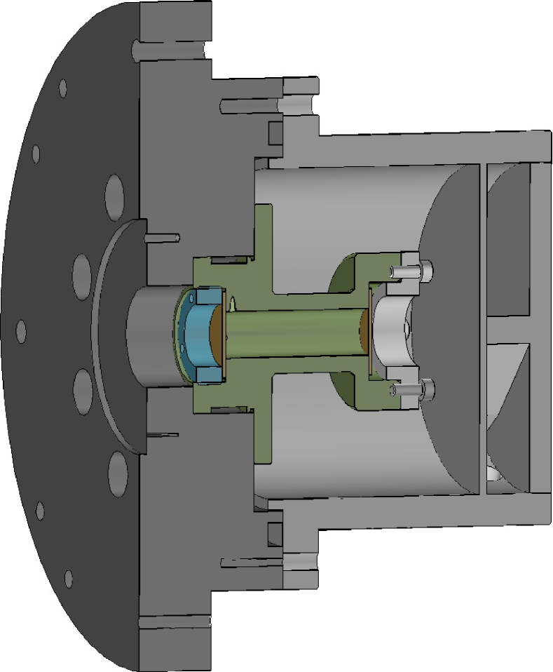
The goal of gas-cell design #3 was to remove the bulk of the beam power deposition from the gas volume. In the same time, to act against the implantation loss in case of the heavier targets, the placement of the catcher was also changed. The second gas-cell target design had a two window configuration with total length of 42 mm with the option to place a catcher foil inside the gas volume at a variable distance from the entrance window (see in Fig. 3). As before, the thinnest commercially available vacuum tight Al foil of 6.5-m thickness was used as entrance window. The entrance window was directly pressed against a small o-ring with a stainless steel ring having a 12-mm-diameter opening. The bigger opening made the beam focusing easier, and the glue less solution made the foil exchange easier.
The exit foil was 10-m-thick aluminum glued onto a frame with 14-mm-diameter opening. The foil frame was pressed against an o-ring to close the gas-cell volume. The beam stop and the rear part of the gas-cell, together with the catcher and exit foils can be detached from the beamline for easy foil exchange. When closed, an o-ring separated the internal volume from the outside atmosphere. #3 cell was successfully used to measure -induced reactions on 124Xe. The catcher was placed 10 mm behind the entrance window, and only 5 mbar initial gas pressure was used, thus the target thickness was reduced to about atoms/cm2. With this configuration the recoils had enough energy to reach and implant into the catcher foil. The results were published in Ref. Halasz16-PRC .
There was still a pressure rise tendency than with the previous gas-cell design, however with lower increase trend. This called to further investigation.
After the xenon campaign, the gas-cell was used to study the 3He(,)7Be reaction at energies around the 7Be proton separation threshold (cell design #4). Because of the reaction kinematics, a much higher target density could be used without risking implantation loss due to the reaction products not reaching the catcher. The pressure was chosen to be 100 mbar, while no intermediate catcher foil was used, exploiting the 42-mm total length of the gas-cell, thus the closing foil served as the catcher. This combination resulted in a target thickness of about atoms/cm2. Because of the higher pressures, a thicker entrance foil of 10 m of Al was employed. The results of these measurement were published in Ref. Szucs19-PRC .
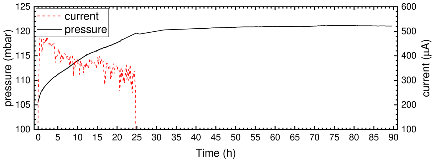
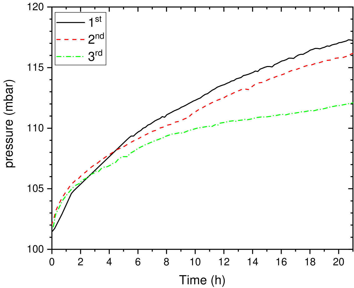
During these campaigns, a continuous pressure increase was still observable as in case of the first gas-cell design. This increase is however proved to be not a temperature effect, since the pressure rise persisted also after the beam was stopped. As an example, in Fig. 4 the pressure during and after a 3He(,)7Be measurements is presented. It is clearly seen that the pressure rise did not vanish for many days after the irradiation, and varies only within a range compatible with temperature effects. It is also visible, that the rate of the increase during the irradiation is dependent on the beam current.
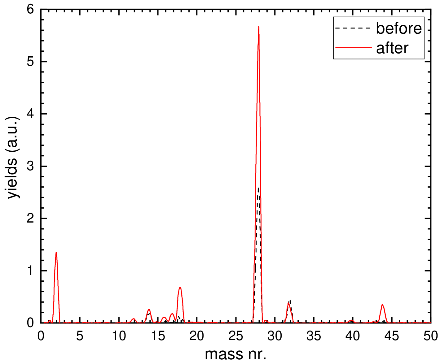
The cause of the increasing pressure was first thought to be an air in-leaking from the atmosphere. This was tested by connecting a residual gas mass spectrometer to the vacuum system, and a sample was drawn from the cell before and after the irradiation of natural xenon (see Fig. 5), while the complete irradiation chamber was placed into a balloon filled with argon gas. Only qualitative analysis could have been done, since no ionization correction was employed. Thus the number of counts in the peaks are only proportional to the amount of the given gas, but those cannot compared to each other. Before the irradiation some nitrogen, oxygen, water vapor and argon is already present (mass nr. 14, 28 for N, N2; 16, 32 for O, O2; 18 for H2O, and 40 for Ar, respectively). These are most probably from the vacuum line between the gas-cell and mass spectrometer (which was used previously for argon measurements). After the irradiation, appearance of mass peaks at 2, 12, 17, 44 was observed in addition to the increase in nitrogen and water vapor signals. The new peaks correspond to H2, C, HO and CO2, respectively, which are molecules and molecular fragments of water and carbon-dioxide. A possible in-leaking is excluded, since no increase in mass 40 appeared, which is the mass of the surrounding argon gas.
Since the extra gas contains elements and molecules typically found in the atmosphere, but no in-leaking is observed, it was concluded that the cause of the pressure rise is the out-gassing of the foils and gas-cell walls, which were exposed to air before the irradiations. This hypothesis is supported by the observation that a lower pressure increase rate is observed for subsequent irradiations (see Fig. 6).
After the 124Xe+ campaign, a new experiment was planned to measure the radiative proton capture reaction on the same isotope. Even though, the half-life of the reaction product is suitable for activation studies, because of the even lower projectile mass, the reaction kinematics posed a complication. A thin gas-cell of 4.2 mm was designed (#5) and an even lower, 3 mbar initial gas pressure (corresponding to about atoms/cm2) was set to have at least 90% recoil implantation probability even at the lowest beam energy of 3 MeV. Successful implantation was achieved, and the half-life of the reaction product and its daughter isotope was precisely measured Szegedi19-NPA .
In summary, the first two window configuration was successfully reduced the gas pressure increase during the irradiations. With detailed investigation, it was proved, that the pressure increase is most probably caused by out-gassing of the internal gas-cell surfaces, and the foils into the gas volume during the irradiations. This effect was not a problem for the 3He(,)7Be investigation, since even the maximum 15% extra gas (considered to be air) in the cell had a negligible effect on the implantation probability, and had also negligible effect on the beam energy loss (which would change the effective reaction energy). In addition to Ref. Szucs19-PRC , this gas-cell was used for cross section measurement of the 3He(,)7Be reaction at around the first resonance in the reaction. The results of this investigation is presented in this paper in Sec. 5.
In case of the heavier targets, thus heavier recoils with lower energy, however, the extra gas entering into the cell during the irradiations could be even twice as much as the initial small amount of target gas ( mbar). Even though, if the extra gas is air that has smaller stopping power than that of the initial heavy gas, after a while it causes significant additional energy loss of the recoils, leading to decreasing implantation probability. In case of the 124Xe investigations, for example, the pressure was never allowed to increase above 8 mbar, while in case of the 124Xep, already 5 mbar was the limit, and the activation was done in multiple cycles, releasing the mixed gas and replaced with fresh, pure 124Xe. This already mitigated the problem and the cross section of the 124Xe(,)128Ba and 124Xe(,n)127Ba reactions were measured Halasz16-PRC , however for the further investigations, an improved design have been made.
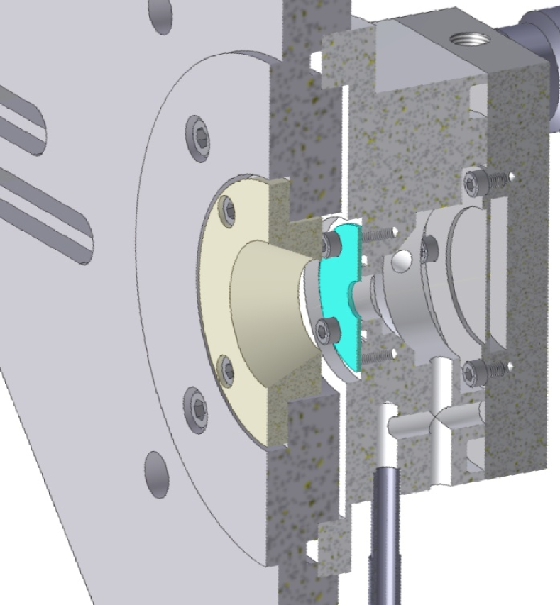
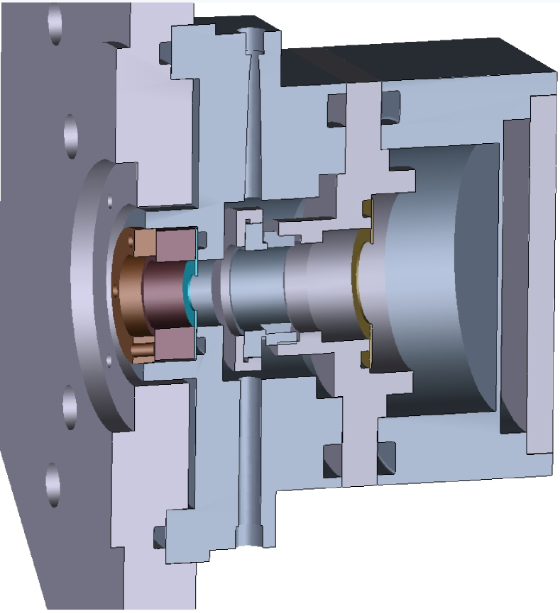
4.3 Two-windowed activation gas-cells surrounded by vacuum (#6, #7 and #8)
To further reduce the probability of air in-leaking from the outside atmosphere and further mitigate the effect of the out-gassing, a new gas-cell design was made with better surface to volume ratio (see Fig. 7). In this most recent design, a standalone replaceable gas-cell can be placed into the gas handling system completely surrounded by the beamline vacuum. Both the entrance and exit foils are pressed against o-rings with tantalum rings of 12-mm-diameter openings. There are two o-rings separating the internal gas-cell volume from the beamline vacuum. With this design, there is no possibility of in-leaking from the surrounding atmosphere, thus any pressure increase have to come from inside of the gas-cell. The only possibility of air to enter the gas-cell is through the connections of the gas handling system, however, those are metal gasket sealed Swagelok VCR connectors, thus highly unlikely to leak.
Three gas-cells were made with different lengths for several different reaction measurements, thus there is no additional catcher foil inside the gas volume. The exit foil always acts as a catcher. The #6 cell with about 42-mm length was used to study the 3He(,)7Be reaction at higher energies of MeV Toth23-PRC . In this case an even thicker catcher foil (up to 25 m) was needed to be able to collect the 7Be recoils with higher energy, which would penetrate the standard 10 m aluminium. A gas-cell with an intermediate length of 10 mm (#7) was used to study the 86Kr(,n)89Sr reaction Kovacs25-NIMA . Since this target gas is lighter than 124Xe, 13 mbar initial target pressure was chosen (corresponding to a target thickness of about atoms/cm2) and not allowed to increase above 27 mbar to get at least 80% implantation probability. In this cases, the reaction cross section was also determined at selected energies employing solid foil targets implanted with 86Kr. These gave consistent results, supporting the accurate recoil implantation probability calculations in case of the gas-cell target.
Further tests for gas-cell optimization are ongoing. With the 10-mm long cell, the 124Xe reaction is planned to be investigated again, while a new 3-mm long gas-cell (#8) is planned to be used for the 124Xep. In this latter two cases, a gas-cell heating is planned before the irradiations to remove as much absorbed gas from the inner surfaces as possible to decrease the pressure increase rate.
4.4 Gas-cell for particle scattering
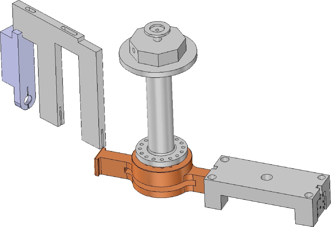
Parallel to the development of gas-cell targets for activation studies, a gas-cell for alpha scattering was designed and manufactured. The design drawing of this scattering gas-cell together with the beam and detector collimator are sown in Fig. 8. In case of a particle scattering experiment, other considerations have to be taken into account than that for the activation studies. For example, the beam particles can scatter on the entrance and/or exit foils not only on the gas, spoiling the recorded spectra. However, with suitable collimation of both the incident beam and the detectors together, these unwanted scattered particles can be avoided. With a collimated detector telescope arrangement each of the detectors see only a particular slice form the gas volume, which is well defined by the collimator acceptance factor Silverstein59-NIM . The 6.5 m entrance and exit foils are placed further away, outside of this acceptance range, thus the detectors do not see the scattered particles from them.
Comparing this configuration with a scattering experiment on solid target, the main differences are the energetic width of the beam arriving in the gas volume, and the energy loss of the scattered particles in the side exit foil (which was 10 m thick Al). As mentioned before, if the reaction cross section and stopping power is nearly constant in the energy range covered by the convolution of the target and beam energy distribution, the determined cross section does not depend on the energetic beam width. However with a single point, this experiments integrate a bigger potion of the excitation function than those on windowless target and sharp beam e.g. Mohr93-PRC . The scattered particles goes through the side exit foil towards the detectors, along which their lose energy. The foil thickness gives lower limit on the scattered particle energy, below which they either stop in the foil, or their energy reduces below the detection threshold. However with a thin enough foil the detection of the scattered particle are still feasible, as will be shown in Sec. 6.
5 The new 3He(,)7Be investigation
5.1 Experimental details
As an example of the application of one of the above described gas-cells, the 3He(,)7Be reaction cross section measurement using gas-cell design #4 will be presented in the following. The cell had nominally 10-m thick aluminum foil entrance and exit windows. The measured entrance foil thicknesses were between m, a given entrance foil was used for multiple irradiations. This thickness causes keV energy loss of the beam particles in the energy range of the present investigations ( MeV) and would widen the energy distribution of an originally mono-energetic beam via straggling to an approximately Gaussian form with a standard deviation of keV. This shall be quadratically added to the original beam energy distribution if it is not mono-energetic as in the present case. The exact thickness of the exit foils was not relevant, because of the reaction kinematics the 7Be recoils have an energy in the range of MeV. This ensures that the 7Be is implanted at a depth of m into the exit foil, well within the nominal 10-m thickness. To minimize the parasitic activity production on any trace amount of foil impurities, a high purity (99.999% Al) foil was chosen as exit window. The length of the gas-cell between the two foils was mm and enclosed 99.999% isotopically pure 3He gas with a pressure of about 100 mbars. The areal number density of the target was derived using the ideal gas law as mentioned before. These parameters resulted in an energetic target thickness of about E keV in the investigated energy range.
The doubly charged beam was provided by the MGC-20 cyclotron of Atomki, where the gas-cell target was installed at the 2A beamline Biri21-EPJP . The typical length of the irradiations varied between h with a typical beam current of A. After the irradiations, the gas was released and the exit foil replaced before a new run was started.
The accumulated 7Be activity in the exit foil was then determined by spectroscopy utilizing the 477.6-keV ray following 10.44% of the 7Be decays Tilley02-NPA . A high purity germanium detector with 100% relative efficiency was used (the same as in Ref. Szucs19-PRC ), which was placed into a 10-cm thick commercial lead shielding layered by cadmium and copper to further reduce the low energy background. The absolute detection efficiency was determined with calibrated radioactive sources, similarly as described in Refs. Szucs19-PRC ; Toth23-PRC . Each sample was counted for at least 3 times, to follow the decrease of the activity, which was always consistent with expectations considering the half-life of 7Be. At the end the results from the different countings on the same sample were combined to reduce the statistical uncertainty.
5.2 Results and discussion
Cross section data have been measured up to the energy range of the first resonance in the 3He(,)7Be reaction with about 100-keV energy steps corresponding to 40-keV steps in the center-of-mass (c.m.) system, and with bigger leaps below. Additional to the statistical uncertainty of the -ray detection, a 4.6% systematic uncertainty had to be taken into account when the absolute scale of the new dataset is compared to other studies. This latter is the quadratic sum of the following partial uncertainties: beam current (3%), -detection efficiency (2.5%), cell length (2.4%) which is the dominating target thickness uncertainty, and -ray branching ratio (0.4%).
| (MeV) | (keV) | (keV) | (barn) |
|---|---|---|---|
| 7.50 | 2582 10 18 | 18 | 6.13 0.18 0.28 |
| 7.70 | 2712 10 18 | 18 | 6.64 0.16 0.31 |
| 7.85 | 2778 10 17 | 18 | 7.07 0.20 0.33 |
| 8.00 | 2851 10 17 | 18 | 7.16 0.19 0.33 |
| 8.10 | 2892 11 17 | 19 | 7.73 0.15 0.36 |
| 8.20 | 2927 12 17 | 19 | 7.50 0.19 0.34 |
| 8.30 | 2989 11 17 | 19 | 7.63 0.15 0.35 |
| 8.40 | 3050 11 16 | 19 | 7.17 0.18 0.33 |
| 8.50 | 3098 11 16 | 19 | 7.62 0.19 0.35 |
The effective energies () were determined considering the energy loss of the beam in the entrance foil and in the gas, setting it at the half of the energetic target thickness. The original beam energy spread of 0.3% is an inherent feature from the cyclotron accelerator. The beam energy uncertainty is taken also to be this value, which in turn is the initial point-by-point energy uncertainty. Additional to this, as discussed in Sec. 3.3, the foil thickness uncertainty adds to this p.b.p. energy uncertainty. Since the energy loss is about % of the initial beam energy, this caused a maximum of % effect. Together with the initial beam energy uncertainty, the point-by-point energy uncertainty () is estimated to be %. The stopping power uncertainty in aluminium is 3.5% according to Ref. Ziegler10-NIMB . Since the thickness of the foil was measured by energy loss, and the beam was also particles, this systematic uncertainty was only once taken into account to avoid double counting. This affects systematically the energy of the whole dataset in the order of % () relative to the beam energy.
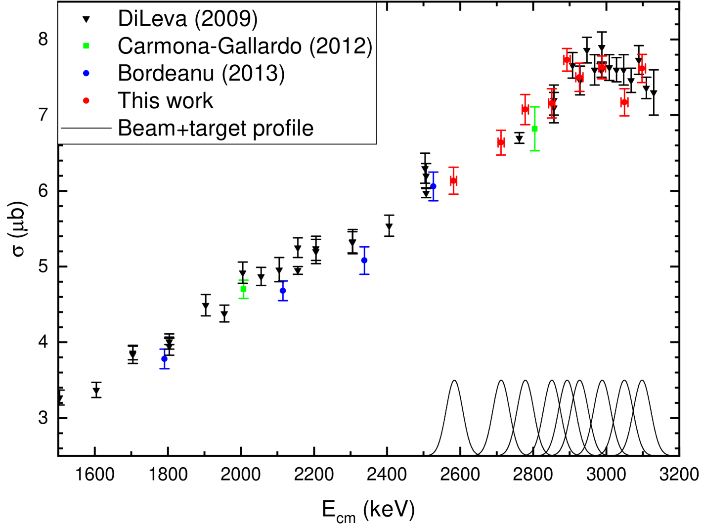
The initial beam has already a 0.3% spread, and it passes through the entrance aluminum foil, which causes an additional beam spread due to straggling. This combined effect causes an beam energetic width when entering the active volume between keV, which is comparable with the target thickness of keV. The convolution of this two results in a function, which is still well described by a Gaussian with a sigma of keV. This value is converted into the c.m. system and called as in Table 1. Since this is one sigma of a Gaussian, the energy range where it is not negligible covers an interval of about 110 keV in the center-of-mass system. To demonstrate this, the integrands are shown in Fig. 9.
As shown in Fig. 9, the new results are in very good agreement with the previous study DiLeva09-PRL . The position and width of the resonance seen by Ref. Barnard64-NP in the scattering channel, and by Ref. DiLeva09-PRL in the capture channel, is confirmed.
6 Toward alpha scattering studies on noble gases
Two experiments were performed with the scattering gas-cell. In both cases, the beam was provided by the MGC-20 cyclotron of Atomki, and the gas-cell target was installed in the scattering chamber behind an analyzing magnet at beamline 4 Biri21-EPJP . This chamber was previously used in many alpha scattering experiments on solid targets e.g. Kiss22-PRC .
The pilot experiment was done with E MeV impinging on the scattering gas-cell containing 100 mbar 4He gas. Inside the gas volume behind the entrance window, this energy corresponds to E MeV. Because the beam and the target are identical, the scattered and recoil particles are indistinguishable. In addition, because of the reaction kinematics, in the laboratory system only forward scattering is possible. The spectra shows a distinct peak in each recorded angle, corresponding to the scattering peak (see Fig. 10).
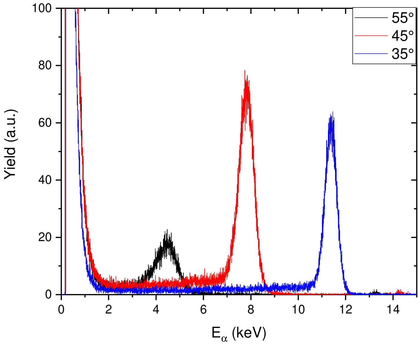
Since the 4He+4He scattering is well studied in the literature, this experiment can be used for validation of the setup and data analysis. In addition, it serves as a benchmark towards the study of the 3He+4He scattering.
The other experiment have been done with the same beam energy, however in this case the gas-cell contained 70 mbar 124Xe gas. A higher pressure can be used than in the activation experiment, since the scattered alpha particles has much higher energy and less energy loss in the gas volume, than the heavy recoils which was the main interest in the activation experiment. The alpha scattering spectra was recorded at several angles. In the spectra shown in Fig. 11, the signal of the scattered alphas on the heavy gas is clearly visible. The observed peak energy follows the expected behavior by taking into account the energy loss in the entrance foil, the reaction kinematic and the energy loss of the exiting alpha particles. At backward angles even the inelastic scattering peak to the first excited state in 128Ba becomes separated from the elastic scattering.
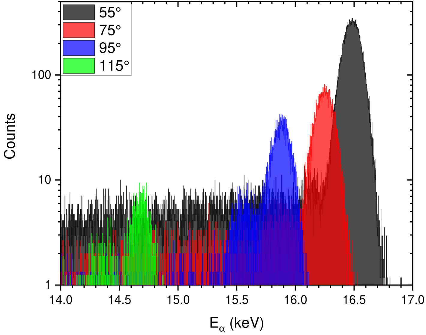
Alpha scattering data on noble gas nuclei is scarce in the literature. By such studies the alpha-nucleus optical potential models can be validated, which is a key ingredient for heavy element nucleosynthesis reaction network calculations.
In summary, the scattering gas-cell performance was tested with both on heavy and low mass noble gas target. The recorded spectra show distinct features, which will later be used for scattering cross section determination. It is planned to exchange the side exit window with one with a lower stopping power. Since the side windows are not exposed to the power deposition of the beam, there is a bigger selection of materials to be used. For example silicon-nitrite vacuum windows of 200 nm thickness is routinely used for in-air PIXE measurements Torok15-NIMB ; Aljboor23-JAAS , where these are exit foils for the low power beam, separating the atmosphere from the beam-line vacuum. Such a foil have more than one order of magnitude lower stopping than that of the presently used 10 m Al. This makes it possible to measure at even lower reaction energies.
7 Summary
In this paper, several stages of the development of thin windowed gas-cell targets were described. Their advantages and disadvantages are shown. Typical experimental and data analysis considerations were detailed, highlighting the valuability and usefulness of such targets. Finally a concrete experimental investigation is shown, which provided new cross section data on the 3He(,)7Be reaction in the energy range of the first resonance in the reaction. In addition, the development of a gas-cell target towards to measure alpha particle scattering cross section on noble gases is presented.
8 Acknowledgments
We thank the operating crews of the Atomki cyclotron accelerator for their assistance during the irradiations, László Palcsu (HUN-REN Atomki) for recording the mass spectra. This work was supported by NKFIH (OTKA FK134845, K134197 and K147010), and by the European Union (ChETEC-INFRA, project no. 101008324).
| Entrance window | Gas-cell | Catcher | Exit window | ||||||||||
| Nr. | Material | Thickness | Diameter | active length | pressure | gas type | Material | Thickness | Diameter | Material | Thickness | Diameter | Reference |
| (m) | (mm) | (mm) | (mbar) | (m) | (mm) | (m) | (mm) | ||||||
| #1 | Ni | 1 | 8 | 30 | 300 | 3He | Cu | 500 | 270 | No exit window | Bordeanu13-NPA | ||
| #2 | Al | 6.5 | 8 | 30 | 50 | 124Xe | Al | 20 | 270 | No exit window | Bordeanu12-NIMA | ||
| #3 | Al | 6.5 | 12 | 10.0 | 5 | 124Xe | Al | 6.5 | 20 | Al | 10 | 18 | Halasz16-PRC |
| #4 | Al | 10 | 12 | 42.0 | 100 | 3He | Identical with the exit window | Al | 10 | 18 | Szucs19-PRC | ||
| #5 | Al | 6.5 | 12 | 4.2 | 5 | 124Xe | Identical with the exit window | Al | 6.5 | 12 | Szegedi19-NPA | ||
| #6 | Al | 6.5-10 | 12 | 41.9 | 100 | 3He | Identical with the exit window | Al | 10-25 | 12 | Toth23-PRC | ||
| #7 | Al | 10 | 12 | 10.0 | 13 | 86Kr | Identical with the exit window | Al | 10 | 12 | Kovacs25-NIMA | ||
| #8 | Al | 6.5 | 12 | 3 | 5 | 124Xe | Identical with the exit window | Al | 10 | 12 | under development | ||
References
- (1) B.D. Fields, Annu. Rev. Nucl. Part. Sci. 61, 47 (2011)
- (2) B. Acharya et al., Solar fusion III: New data and theory for hydrogen-burning stars (2024), 2405.06470, http://arxiv.org/abs/2405.06470
- (3) W. Hauser, H. Feshbach, Phys. Rev. 87, 366 (1952)
- (4) T. Rauscher, Phys. Rev. C 73, 015804 (2006)
- (5) W. Rapp et al., Astrophys. J. 653, 474 (2006)
- (6) J. Bliss, A. Arcones, F. Montes, J. Pereira, Phys. Rev. C 101, 055807 (2020)
- (7) A. Psaltis et al., ApJ 935, 27 (2022)
- (8) P.E. Lhuillier et al., J. Nucl. Mater. 417, 504 (2011)
- (9) S. Ibrahim et al., Vacuum 224, 113184 (2024)
- (10) F. Ferraro et al., Eur. Phys. J. A 54, 44 (2018)
- (11) S.N. Paneru et al., Phys. Rev. C 109, 015802 (2024)
- (12) K. Schmidt et al., Nucl. Instrum. Meth. A 911, 1 (2018)
- (13) A. Yadav, K. Schmidt, D. Bemmerer, EPJ Web Conf. 279, 13002 (2023)
- (14) C. Bordeanu et al., Nucl. Instrum. Meth. A 693, 220 (2012)
- (15) Á. Tóth et al., Phys. Rev. C 108, 025802 (2023)
- (16) S. Agostinelli et al., Nucl. Instrum. Meth. A 506, 250 (2003)
- (17) J. Allison et al., IEEE Trans. Nucl. Sci. 53, 270 (2006)
- (18) J. Allison et al., Nucl. Instrum. Meth. A 835, 186 (2016)
- (19) C. Iliadis, Nuclear Physics of Stars (WILEY-VCH Verlag Gmbh Co. KGaA, Weinheim, 2007)
- (20) C. Rolfs, W. Rodney, Cauldrons in the Cosmos (The University of Chicago Press, Chicago, 1988)
- (21) T. Szücs et al., Phys. Rev. C 100, 065803 (2019)
- (22) J.F. Ziegler, M.D. Ziegler, J.P. Biersack, Nucl. Instrum. Meth. B 268, 1818 (2010)
- (23) C. Bordeanu et al., Nucl. Phys. A 908, 1 (2013)
- (24) Z. Halász et al., Phys. Rev. C 94, 045801 (2016)
- (25) T.N. Szegedi et al., Nucl. Phys. A 986, 213 (2019)
- (26) S.R. Kovács et al., Nucl. Instrum. Meth. A 1073, 170272 (2025)
- (27) E.A. Silverstein, Nucl. Inst. Meth. 4, 53 (1959)
- (28) P. Mohr et al., Phys. Rev. C 48, 1420 (1993)
- (29) S. Biri et al., Eur. Phys. J. Plus 136, 247 (2021)
- (30) D.R. Tilley et al., Nucl. Phys. A 708, 3 (2002)
- (31) A. Di Leva et al., Phys. Rev. Lett. 102, 232502 (2009)
- (32) M. Carmona-Gallardo et al., Phys. Rev. C 86, 032801 (2012)
- (33) A.C.L. Barnard, C.M. Jones, G.C. Phillips, Nucl. Phys. 50, 629 (1964)
- (34) G.G. Kiss et al., Phys. Rev. C 106, 015802 (2022)
- (35) Zs. Török et al., Nucl. Instrum. Meth. B 362, 167 (2015)
- (36) S. Aljboor et al., J. Anal. At. Spectrom. 38, 57 (2023)