Controlling the sign of optical forces using metaoptics
Abstract
Precise manipulation of small objects using light holds transformative potential across diverse fields. While research in optical trapping and manipulation predominantly relies on the attraction of solid matter to light intensity maxima, here we demonstrate that meta-optics enables a departure from this accepted behavior. Specifically, we present deterministic control over the sign of optical forces exerted on a metasurface integrated on a suspended silicon nanomembrane. By tailoring the geometry of the constituent meta-atoms, we engineer the coherent superposition of their multipolar modes, and consequently, the net optical force experienced by the metasurface within a phase-controlled optical standing wave. In excellent agreement with 3D numerical simulations, we experimentally realize both attractive and repulsive forces on distinct metasurface designs, directly mirroring the behavior of two-level systems interacting with optical fields. This work establishes a versatile platform for the optical control of nanoscale mechanical systems, opening new avenues for both fundamental research and engineering.
The interaction of light with matter involves the fundamental exchange of photon momentum, resulting in radiation pressure. This phenomenon, predicted by Maxwell’s electromagnetic theory, was experimentally confirmed in 1901 by Lebedev [1], and Nichols and Hull [2], followed by the observation of photon recoil by Poynting and Barlow [3]. Although radiation pressure under terrestrial conditions is usually too small to be noticed, it plays an important role in the formation of stars [4] and in the dynamics of spacecrafts in outer space [5, 6], where the radiation pressure is the main force next to gravity. Nowadays, radiation pressure is even harnessed on demand, for instance in photonic sails to propel ultralight satellites through space [7, 8, 9] or to control optomechanical systems across a wide range of sizes [10, 11, 12].
However, light-matter interaction is not limited to repulsive forces. Ashkin’s seminal work revealed that polarizable objects placed in an inhomogeneous light field experience a force that attracts them towards the highest intensity [13, 14, 15]. This discovery laid the foundation for the field of optical tweezers, enabling the precise control and manipulation of microscopic particles. Nowadays, optical tweezers are widely used in cell-biology [16, 17, 18], climate research with aerosols [19], quantum optics and quantum simulations with ultracold atoms and molecules [20, 21], and levitation optomechanics [22, 23], among others. Further experimental exploration revealed surprising effects, such as pulling forces from engineered unfocused light beams, coined tractor beams (see discussion in [24, 25, 26, 27]) or non-reciprocal optical binding [28, 29].
The optical forces experienced by a specimen exposed to a light intensity gradient are hereby fundamentally governed by its polarizability, offering additional control through its geometrical and structural properties. This was first highlighted in 1977 when Askhin and Diedzic observed enhanced radiation pressure on levitated oil drops from a probe beam spectrally matching their Mie resonances [30]. Similar resonant effects were also studied in plasmonic nanoparticles [31, 32, 33] and nanodiamonds hosting multiple nitrogen-vacancies [34]. More recently, drawing an analogy to two-level atoms [35], we proposed to exploit electromagnetic Mie resonances in high-permittivity meta-atoms for optical trapping at intensity minima [36]. Furthermore, unconventional switchable optical forces were reported in nanoparticles made of temperature-sensitive phase change materials [37].
In this work, we demonstrate full control over optical forces on a metasurface [38, 39, 40, 41]. Through precise meta-atom design, we experimentally achieve a controllable reversal of the optical forces, from repulsive to attractive, in excellent agreement with 3D multi-physics simulations. Leveraging solely geometry and intrinsic material properties, our method generates these forces without complex beam engineering, offering new possibilities for scalable light-based manipulation of matter.
System description
The studied configuration features a free-standing metasurface placed in an optical standing wave, as illustrated in Fig. 1a. The metasurface design consists of a periodic array of identical silicon discs, each with radius , separated by short connectors of length (see Fig. 1b). To minimize mechanical stress and allow free motion, the metasurface is suspended from a frame using undulated tethers [42]. Given that a single optical beam carries significant photon momentum along its propagation direction, it cannot generate a pulling force [24]. Hence, we opted for a standing wave field formed by two counter-propagating Gaussian beams. This configuration cancels the scattering force, thereby ensuring that the gradient force dominates. Within the Gaussian beam approximation, the gradient force experienced by the metasurface is given by where represents the real part of the effective polarizability, and the intensity gradient at the metasurface position . The effective polarizability is primarily determined by the magnetic and electric dipolar, quadrupolar and octupolar modes [24, 36] supported by each meta-atom.
Using this configuration, we aim to demonstrate accurate control over both the magnitude and direction of the total force by tuning geometrical parameters to engineer the coherent superposition of Mie multipolar modes [24]. Specifically, we leverage the dependence of the scattering radiation pattern of silicon discs, and hence the net optical force they experience, on the ratio of their radius to the laser wavelength [36]. By varying disc radii and separations , we explore a wide range of force amplitudes and directions. Depending on the optical wavelength, each metasurface acts as a high- or low-field seeker attracted to intensity maxima or minima, in full analogy to two-level systems [35].
Theoretical model
To estimate the total optical force experienced by the freely moving metasurface, we exploit its resonant mechanical mode, which exhibits a frequency-dependent amplitude response to an external driving force [43, 44]. We model the system as a driven underdamped harmonic oscillator, characterized by the oscillator’s mechanical eigenfrequency , its mass and the amplitude decay rate due to clamping losses and gas collisions at atmospheric pressure. The optical driving force is generated by modulating the intensity of the standing wave pattern , such that a time-dependent optical force is exerted on the membrane. In this context, the optical driving force prevails over the thermal driving force (see Supplementary Information Sec. V). The displacement of the oscillator, , is characterized by its frequency dependent amplitude and its phase across the resonance.
Eventually, the sign of the intensity gradient at the membrane’s equilibrium position along the standing wave dictates the direction of the displacement. While the amplitude and phase relationship between and are invariant for high- and low-field seekers, their displacement directions are opposite (see Fig. 1c). However, since measurements are referenced to the driving signal of , this results in an effective reversal of the force and a phase shift in the measured motion relative to the modulation signal, when comparing high- and low-field seekers at the same position. The measured phase between and can thus take on two distinct values, given by:
| (1) |
where we refer to in-phase (out-of-phase) oscillations as positive (negative) force (). Note that, depending on the sign of the intensity slope, both high- and low-field seekers can exhibit positive and negative force behavior. To account for this we define . The phase term () corresponds here to a low- (high-) field seeker that is repelled (attracted) by high intensity. This consequently leads to () for the positive (negative) intensity slope of the standing wave pattern.
Experimental implementation
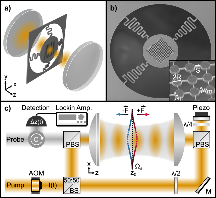
The experimental configuration is illustrated in Fig. 1c. Two counter-propagating, equally -polarized beams at a wavelength with power are focused by two lenses of numerical aperture NA=0.4 resulting in a beam waist smaller than the metasurface area. Both beams are phase-stabilized to form an interference pattern along the optical axis (shown in yellow) where the relative position of intensity maxima and membrane position is controlled with the beams’ relative phase . The optical external driving force is generated by modulating the optical intensity of this standing wave with an acousto-optic modulator (AOM) at and amplitude . The metasurface, consisting of an array of identical discs, is patterned on freestanding crystalline silicon membranes of thickness [45]. The discs in the array are connected by thin nanobeams of width .
An additional single cross-polarized beam co-propagates along the optical axis (depicted in gray in Fig. 1c). The backscattered light of this probe beam is phase modulated by the motion of the membrane and therefore can be used for optical displacement readout via phase sensitive homodyne detection [46]. By using a lock-in operation, we detect the membrane motion with the relative phase between the membrane motion and the reference signal (see Supplementary Information Sec. III).
| [nm] | [nm] | [kHz] | [kHz] | ||
|---|---|---|---|---|---|
| 345 | 530 | 94.81 | 10.32 | ||
| 485 | 430 | 92.55 | 9.54 |
We first focus on two membranes (see Tab. 1), and , which exhibit high- and low-field seeker behavior, respectively. These membranes are positioned at the rising slope of the intensity field ().
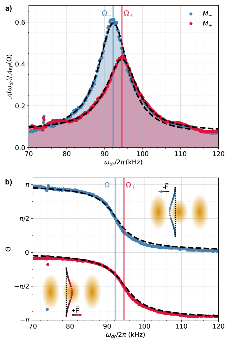
Fig. 2 depicts the motional response of membranes and under the driving force with varying at atmospheric pressure. The amplitude is normalized by the experimental amplitude response of an unstructured flat membrane acting as a mirror. This mirror membrane experiences radiation pressure force from a single beam [47], where and are the reflectivity and absorption of the unstructured flat membrane, the optical power, and the speed of light (see Supplementary Information Sec. IV).
As shown in Fig. 2a, the driven motion exhibits the typical Lorentzian profile of a mechanical resonance, centered at (solid lines) and with a linewidth (see Tab. 1). Fig. 2b displays the phase response of the driven membranes and . The dashed lines represent fits to the theory (see Supplementary Information Sec. III). We observe that the membrane (red) oscillates in phase with the reference signal at low . Upon exceeding its resonance frequency () it undergoes the expected phase jump. indicating that the oscillator response lags behind the driving force. In contrast, oscillates out of phase () already for and changes to an in-phase oscillation with respect to the reference signal () across the resonance. The different phase responses, in excellent agreement with the theory, demonstrate that the membranes and experience opposite force signs (see insets in Fig. 2b). Specifically, acts as a high-field seeker, drawn to the intensity maximum, whereas behaves as a low-field seeker, drawn atypically to the intensity minimum, a scenario difficult to achieve with dielectric structures in the dipole regime [48].
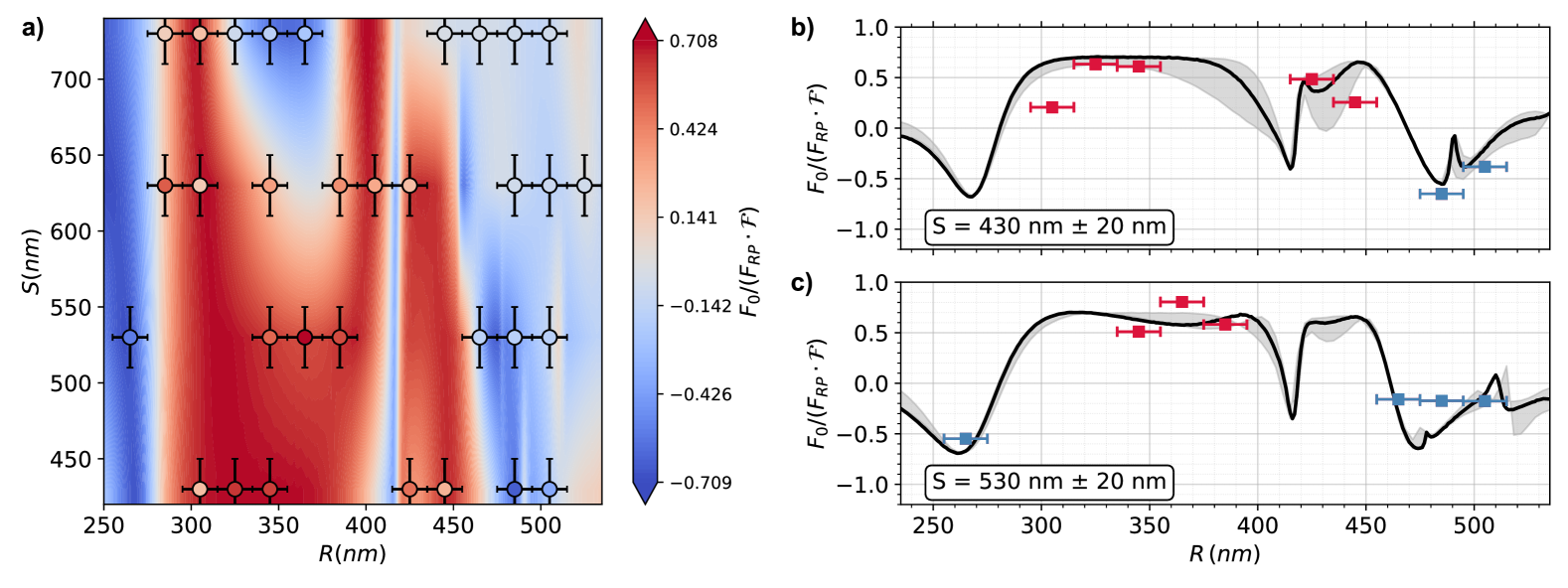
To demonstrate complete control over the optical force and its dependence on structural parameters, we fabricate a series of metasurfaces systematically exploring the parameters space where the radius ranged from to and the separation ranged from to . For each metasurface, we position the membrane at and modulate the intensity at for each metasurface.
In Fig. 3a we compare the measured force amplitudes (circles) with simulation. The geometric filling factor is equal to the mass ratio of the metasurface and mirror membrane. The contourplot displays the simulations (see Supplementary Information Sec. II). Fig. 3b and c show line plots for constant separations and exhibiting the largest negative force and largest positive force with a magnitude comparable to the radiation pressure . The fabrication uncertainty of and is represented by the experimental error bars and the gray-shaded area in the simulation. We observe a broad tunability of the force that is only weakly affected by the separation . However, at smaller radii, the force amplitude tends to be larger with frequent negative values, whereas at midrange radii, the amplitude is predominantly positive. We find experiment and simulation in good agreement, confirming the tunability of optical forces by structural parameters and .
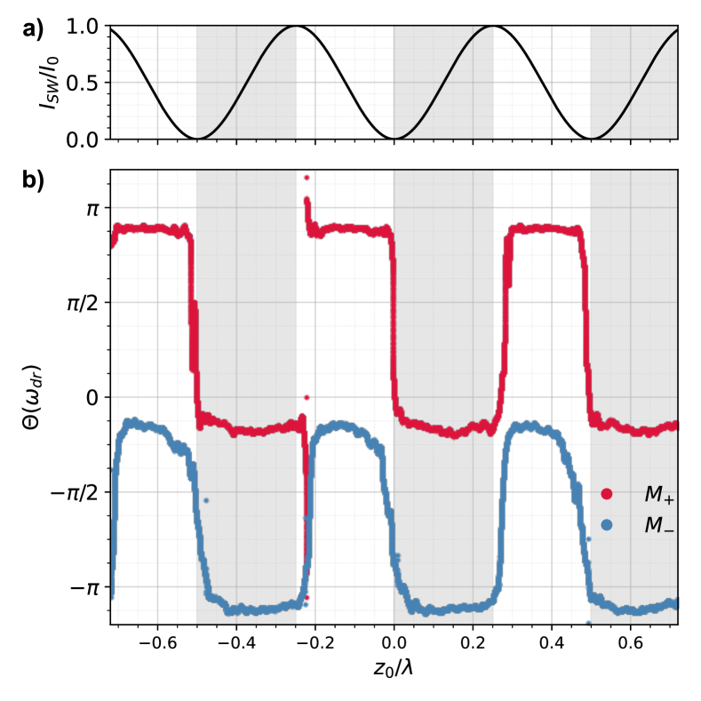
As noted above, the sign of the optical force depends on both the membrane’s high- or low-field seeking behavior () and its position within the standing wave, determined by the intensity gradient (). To demonstrate the position dependence of the relative phase between optical force and reference signal, we sweep the standing wave relative to the membrane’s position across several wavelengths by tuning the phase , while simultaneously driving the membrane’s motion at . For this analysis, we deploy and (see Tab. 1). Figure 4a shows the theoretical intensity along the standing wave. The measured lock-in phase for (red) and (blue) is shown in Fig. 4b, displaying a constant phase difference of between and . For a negative intensity slope (), exhibits a phase shift of , while remains in phase at . The phase shifts reverses sweeping to a positive intensity gradient (), further confirming the opposite signs of optical forces in these two metasurfaces.
Conclusions
In summary, we demonstrate deterministic control over both the amplitude and direction of optical forces on suspended high-refractive-index metasurfaces via advanced mode engineering. Most notably, we unveil the counterintuitive phenomenon of low-field-seeking behavior, its attraction to intensity minima, enabled by the interplay of Mie multipolar modes. Beyond its fundamental significance, this approach establishes a powerful and versatile platform for optical force engineering, potentially relevant to light sails and optomechanics.
Acknowledgements: This research was supported by the European Research Council (ERC) through grant Q-Xtreme ERC 2020-SyG (grant agreement number 951234). We acknowledge valuable discussions with the Q-Xtreme synergy consortium.
Author contributions -
A.A. performed the numerical simulations, fabricated the device, performed the measurements and analyzed the data. A.A. and B.M. designed and implemented the optical setup. N.M developed the theoretical expressions. N.M. and R.Q. conceptualized the experiments. All authors discussed the results and contributed to writing the manuscript.
References
- Lebedew [1901] P. Lebedew, Untersuchungen über die druckkräfte des lichtes, Ann. Phys. 311, 433 (1901).
- Nichols and Hull [1901] E. F. Nichols and G. F. Hull, A preliminary communication on the pressure of heat and light radiation, Phys. Rev. (Series I) 13, 307 (1901).
- Poynting and Barlow [1910] J. H. Poynting and G. Barlow, Bakerian lecture:—the pressure of light against the source: the recoil from light, Proc. R. Soc. Lond. A 83, 534 (1910).
- Murray et al. [2009] N. Murray, E. Quataert, and T. A. Thompson, The disruption of giant molecular clouds by radiation pressure & the efficiency of star formation in galaxies, Astrophys. J. 709, 191 (2009).
- Anselmo et al. [1983] L. Anselmo, B. Bertotti, P. Farinella, A. Milani, and A. Nobili, Orbital perturbations due to radiation pressure for a spacecraft of complex shape, Celest. Mech. 29, 27 (1983).
- Scheeres [1999] D. J. Scheeres, Satellite dynamics about small bodies: Averaged solar radiation pressure effects, J. Astronaut. Sci. 47, 25 (1999).
- Ilic and Atwater [2019] O. Ilic and H. A. Atwater, Self-stabilizing photonic levitation and propulsion of nanostructured macroscopic objects, Nat. Photon. 13, 289 (2019).
- Michaeli et al. [2025] L. Michaeli, R. Gao, M. D. Kelzenberg, C. U. Hail, A. Merkt, J. E. Sader, and H. A. Atwater, Direct radiation pressure measurements for lightsail membranes, Nat. Photon. 19, 369 (2025).
- Spencer et al. [2021] D. A. Spencer, B. Betts, J. M. Bellardo, A. Diaz, B. Plante, and J. R. Mansell, The lightsail 2 solar sailing technology demonstration, Adv. Space Res. 67, 2878 (2021).
- Abramovici et al. [1992] A. Abramovici, W. E. Althouse, R. W. Drever, Y. Gürsel, S. Kawamura, F. J. Raab, D. Shoemaker, L. Sievers, R. E. Spero, K. S. Thorne, et al., Ligo: The laser interferometer gravitational-wave observatory, Science 256, 325 (1992).
- Cohadon et al. [1999] P.-F. Cohadon, A. Heidmann, and M. Pinard, Cooling of a mirror by radiation pressure, Phys. Rev. Lett. 83, 3174 (1999).
- Aspelmeyer et al. [2014] M. Aspelmeyer, T. J. Kippenberg, and F. Marquardt, Cavity optomechanics, Rev. Mod. Phys. 86, 1391 (2014).
- Ashkin et al. [1986] A. Ashkin, J. M. Dziedzic, J. E. Bjorkholm, and S. Chu, Observation of a single-beam gradient force optical trap for dielectric particles, Opt. Lett. 11, 288 (1986).
- Ashkin and Dziedzic [1971] A. Ashkin and J. Dziedzic, Optical levitation by radiation pressure, Appl. Phys. Lett. 19, 283 (1971).
- Ashkin [1970] A. Ashkin, Acceleration and trapping of particles by radiation pressure, Phys. Rev. Lett. 24, 156 (1970).
- Zhang and Liu [2008] H. Zhang and K.-K. Liu, Optical tweezers for single cells, J. R. Soc. Interface 5, 671 (2008).
- Goel and Vogel [2008] A. Goel and V. Vogel, Harnessing biological motors to engineer systems for nanoscale transport and assembly, Nat. Nanotechnol. 3, 465 (2008).
- Zhu et al. [2020] R. Zhu, T. Avsievich, A. Popov, and I. Meglinski, Optical tweezers in studies of red blood cells, Cells 9, 545 (2020).
- Burnham and McGloin [2006] D. R. Burnham and D. McGloin, Holographic optical trapping of aerosol droplets, Opt. Express 14, 4175 (2006).
- Grimm et al. [2000] R. Grimm, M. Weidemüller, and Y. B. Ovchinnikov, Optical Dipole Traps for Neutral Atoms, Adv. At. Mol. Opt. Phys., Vol. 42 (Academic Press, 2000) pp. 95–170.
- Kaufman and Ni [2021] A. M. Kaufman and K.-K. Ni, Quantum science with optical tweezer arrays of ultracold atoms and molecules, Nat. Phys. 17, 1324 (2021).
- Gonzalez-Ballestero et al. [2021] C. Gonzalez-Ballestero, M. Aspelmeyer, L. Novotny, R. Quidant, and O. Romero-Isart, Levitodynamics: Levitation and control of microscopic objects in vacuum, Science 374 (2021).
- Millen et al. [2020] J. Millen, T. S. Monteiro, R. Pettit, and A. N. Vamivakas, Optomechanics with levitated particles, Rep. Prog. Phys. 83, 026401 (2020).
- Chen et al. [2011] J. Chen, J. Ng, Z. Lin, and C. T. Chan, Optical pulling force, Nat. Photonics 5, 531 (2011).
- Ding et al. [2019] W. Ding, T. Zhu, L.-M. Zhou, and C.-W. Qiu, Photonic tractor beams: a review, Adv. Photonics 1, 024001 (2019).
- Shvedov et al. [2014] V. Shvedov, A. R. Davoyan, C. Hnatovsky, N. Engheta, and W. Krolikowski, A long-range polarization-controlled optical tractor beam, Nat. Photon. 8, 846 (2014).
- Brzobohatỳ et al. [2013] O. Brzobohatỳ, V. Karásek, M. Šiler, L. Chvátal, T. Čižmár, and P. Zemánek, Experimental demonstration of optical transport, sorting and self-arrangement using a ‘tractor beam’, Nat. Photon. 7, 123 (2013).
- Dholakia and Zemánek [2010] K. Dholakia and P. Zemánek, Colloquium: Gripped by light: Optical binding, Rev. Mod. Phys. 82, 1767 (2010).
- Rieser et al. [2022] J. Rieser, M. A. Ciampini, H. Rudolph, N. Kiesel, K. Hornberger, B. A. Stickler, M. Aspelmeyer, and U. Delić, Tunable light-induced dipole-dipole interaction between optically levitated nanoparticles, Science 377, 987 (2022).
- Ashkin and Dziedzic [1977] A. Ashkin and J. M. Dziedzic, Observation of resonances in the radiation pressure on dielectric spheres, Phys. Rev. Lett. 38, 1351 (1977).
- Dienerowitz et al. [2008] M. Dienerowitz, M. Mazilu, and K. Dholakia, Optical manipulation of nanoparticles: a review, J. Nanophoton 2, 021875 (2008).
- Arias-González and Nieto-Vesperinas [2003] J. R. Arias-González and M. Nieto-Vesperinas, Optical forces on small particles: attractive and repulsive nature and plasmon-resonance conditions, J. Opt. Soc. Am. A 20, 1201 (2003).
- Zelenina et al. [2006] A. S. Zelenina, R. Quidant, G. Badenes, and M. Nieto-Vesperinas, Tunable optical sorting and manipulation of nanoparticles via plasmon excitation, Opt. Lett. 31, 2054 (2006).
- Juan et al. [2017] M. L. Juan, C. Bradac, B. Besga, M. Johnsson, G. Brennen, G. Molina-Terriza, and T. Volz, Cooperatively enhanced dipole forces from artificial atoms in trapped nanodiamonds, Nat. Phys. 13, 241 (2017).
- Vetsch et al. [2010] E. Vetsch, D. Reitz, G. Sagué, R. Schmidt, S. Dawkins, and A. Rauschenbeutel, Optical interface created by laser-cooled atoms trapped in the evanescent field surrounding an optical nanofiber, Phys. Rev. Lett. 104, 203603 (2010).
- Lepeshov et al. [2023] S. Lepeshov, N. Meyer, P. Maurer, O. Romero-Isart, and R. Quidant, Levitated optomechanics with meta-atoms, Phys. Rev. Lett. 130, 233601 (2023).
- Mao et al. [2024] L. Mao, I. Toftul, S. Balendhran, M. Taha, Y. Kivshar, and S. Kruk, Switchable optical trapping of mie-resonant phase-change nanoparticles, Laser Photonics Rev. 19, 2400767 (2024).
- Chen et al. [2016] H.-T. Chen, A. J. Taylor, and N. Yu, A review of metasurfaces: physics and applications, Rep. Prog. Phys. 79, 076401 (2016).
- Yu et al. [2011] N. Yu, P. Genevet, M. A. Kats, F. Aieta, J.-P. Tetienne, F. Capasso, and Z. Gaburro, Light propagation with phase discontinuities: generalized laws of reflection and refraction, Science 334, 333 (2011).
- Kruk and Kivshar [2017] S. Kruk and Y. Kivshar, Functional meta-optics and nanophotonics governed by mie resonances, ACS Photon. 4, 2638 (2017).
- Kuznetsov et al. [2024] A. I. Kuznetsov, M. L. Brongersma, J. Yao, M. K. Chen, U. Levy, D. P. Tsai, N. I. Zheludev, A. Faraon, A. Arbabi, N. Yu, et al., Roadmap for optical metasurfaces, ACS Photon. 11, 816 (2024).
- Chou et al. [2015] H.-M. Chou, M.-J. Lin, and R. Chen, Fabrication and analysis of awl-shaped serpentine microsprings for large out-of-plane displacement, J. Micromech. Microeng. 25, 095018 (2015).
- Cuairan et al. [2022] M. T. Cuairan, J. Gieseler, N. Meyer, and R. Quidant, Precision calibration of the duffing oscillator with phase control, Phys. Rev. Lett. 128, 213601 (2022).
- Ricci et al. [2019] F. Ricci, M. T. Cuairan, G. P. Conangla, A. W. Schell, and R. Quidant, Accurate mass measurement of a levitated nanomechanical resonator for precision force-sensing, Nano Lett. 19, 6711 (2019).
- Afridi et al. [2023] A. Afridi, J. Gieseler, N. Meyer, and R. Quidant, Ultrathin tunable optomechanical metalens, Nano Lett. 23, 2496 (2023).
- Tebbenjohanns et al. [2021] F. Tebbenjohanns, M. L. Mattana, M. Rossi, M. Frimmer, and L. Novotny, Quantum control of a nanoparticle optically levitated in cryogenic free space, Nature 595, 378 (2021).
- Swartzlander [2017] G. A. Swartzlander, Radiation pressure on a diffractive sailcraft, J. Opt. Soc. Am. B 34, C25 (2017).
- Dago et al. [2024] S. Dago, J. Rieser, M. A. Ciampini, V. Mlynář, A. Kugi, M. Aspelmeyer, A. Deutschmann-Olek, and N. Kiesel, Stabilizing nanoparticles in the intensity minimum: feedback levitation on an inverted potential, Opt. Express 32, 45133 (2024).
Methods
.1 Fabrication of metasurfaces
To fabricate the metasurfaces, we employ top-down electron beam lithography. Commercially available free standing crystalline (100) silicon membranes from Norcada Inc. serve as material substrate. The membrane sample is spin coated with the AR-P 6200.04 positive photo-resist with a thickness of followed by baking for 1 minute at 150∘C. Afterwards, electron beam exposure is carried out followed by 90 seconds in the AR 600-546 developer at room temperature. We etch the silicon membrane using HBr chemistry with an inductively coupled plasma etcher. Finally,the photo-resist is stripped off with an oxygen plasma etcher. The patterned metasurface of area is placed in the center of a circular membrane of diameter which is connected by undulated tethers to the substrate frame.
.2 Simulations
The optical forces are numerically simulated using the RF module of the commercially available solver COMSOL Multiphysics. We employ a scattered field formulation, defining a meta-atom composed of silicon discs with cross beams suspended in air, with periodic boundary conditions applied in the and directions. Perfectly matched layers are implemented along to minimize boundary reflections.