Experimental Analysis of Multipath Characteristics in Indoor Distributed Massive MIMO Channels
Abstract
Distributed massive multiple-input multiple-output (MIMO), also known as cell-free massive MIMO, has emerged as a promising technology for sixth-generation (6G) wireless networks. This letter introduces an indoor channel measurement campaign designed to explore the behavior of multipath components (MPCs) in distributed massive MIMO channels. Fully coherent channels were measured between eight distributed uniform planar arrays (128 elements in total) and a 12-meter user equipment route. Furthermore, a method is introduced to determine the order (single- or multi-bounce) of MPC interaction by leveraging map information and MPC parameters. In addition, a Kalman filter-based framework is used for identifying the MPC interaction mechanisms (reflection or scattering/diffraction/mixed). Finally, a comprehensive MPC-level characterization is performed based on the measured channels, including the significance of the single-bounce MPCs, the spherical wavefront features, the birth-and-death processes of the MPCs, and the spatial distribution of reflections. The findings serve as a valuable reference for understanding MPC propagation behavior, which is necessary for accurate modeling of indoor distributed massive MIMO channels.
Index Terms:
Channel measurements, distributed massive MIMO, multipath characterization, MPC birth-and-death process, spherical wavefront.I Introduction
As a promising technology for sixth-generation (6G) wireless networks, distributed massive multiple-input multiple-output (MIMO), also known as cell-free massive MIMO [1], is expected to combine the advantages of both massive MIMO and cell-free networks. Compared to co-located massive MIMO, distributed massive MIMO aims to contribute to uniform coverage and improve communication reliability [2].
In order to optimize the design of distributed massive MIMO systems, it is necessary to perform measurement campaigns to experimentally investigate its underlying propagation channels. Extensive research has been carried out in this regard. For example, outdoor channel measurements were reported in [3] with a widely distributed antenna array spread over a 46.5 m range. Key channel properties, including time-variant delay spread, Doppler spread, and path loss, were investigated. Channel measurements in [4] focused on an urban scenario, analyzing multi-link channels between 80 user equipment (UE) and more than 20,000 access point (AP) locations in terms of path loss, shadowing, and delay spread. Regarding indoor channel measurements, distributed MIMO channels in an industrial office were investigated in [5] from a perspective of multi-user capacity performance through various antenna topologies. In addition, a system with twelve fully coherent distributed antennas was introduced in [6] for industrial channel measurements. Further measurements in [7, 8] focused on an indoor laboratory environment, in which user separability and non-wide-sense stationarity of the measured channels are investigated.
The aforementioned studies allow for valuable insight into the large-scale fading properties of channels. However, they are limited in the investigation into small-scale fading, particularly multipath effects, which is a key factor affecting system performance. Studies in [9, 10, 11] found that the deployment of massive antennas results in spatially varying multipath components (MPCs). This is even more evident in distributed massive MIMO due to the larger separation between APs. Specifically, distributed APs may observe different MPCs with various propagation behavior, further increasing the diversity of MPC characteristics in the channel. Understanding MPC-level channel characterization is not only fundamental for accurately parameterization of ray-based channel models, but is also important in system design and practical applications. For example, the performance of beamforming and radio-based positioning technologies is highly dependent on the underlying multipath propagation characteristics of the channel [12, 13].
To the best of our knowledge, the characterization of MPCs in distributed massive MIMO channels, here strengthened by using actual measurement data, has not been completely addressed. To fill this gap, this letter presents an indoor distributed MIMO channel measurement campaign. Then a method for determining the order of the MPC interaction is introduced, followed by a Kalman filter-based framework designed to identify the reflected MPCs. The framework can simultaneously estimate the virtual scatterers (VSs)/anchors, which is necessary for channel modeling and other applications, e.g., radio sensing and localization. Finally, MPC characteristics of the measured channels are investigated, including the significance of the single-bounce MPCs, the spherical wavefront properties as well as birth-and-death processes of the MPCs, and the spatial distribution of reflections within the channels.
II Indoor Distributed MIMO Channel Measurements
The indoor channel measurements were performed in a laboratory room at Lund University, Sweden. The room features an environment with various objects that contribute to a rich scattering environment. The signals can interact with these objects through reflections, diffraction, or scattering, allowing for MPC investigations with diverse propagation behavior.
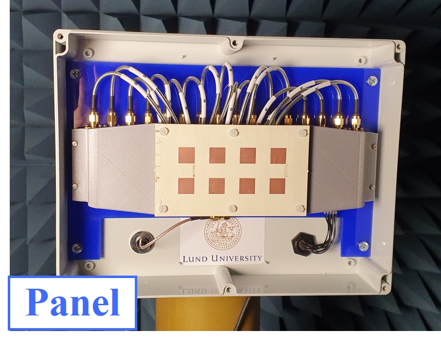
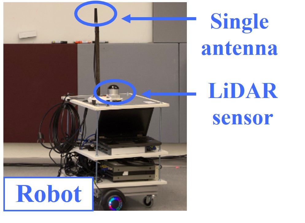
A switch-based wideband distributed MIMO channel sounder [14] is deployed, integrating multiple NI universal software radio peripherals (USRPs), SP16T radio frequency (RF) switches, and a pair of Rubidium clocks. Eight uniform planar arrays (UPAs) are deployed on the base station (BS) side, here referred to as ‘panels’. As illustrated in Fig. 1a, each panel is equipped with eight dual polarized patch antennas (16 ports), designed for a 5–6 GHz frequency band (S11 dB). The spacing between neighboring patch antennas is 26.7 mm, corresponding to approximately half a wavelength in this frequency range. On the UE side, a single omnidirectional monopole antenna was used with an operating frequency band of 3.5–8 GHz.
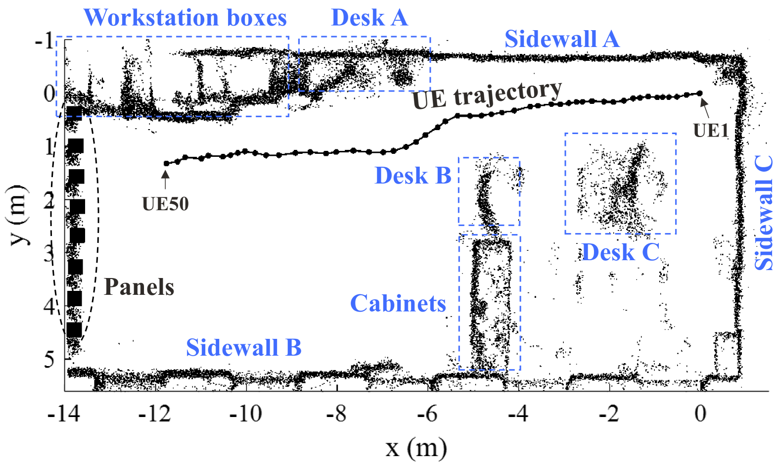
The measurements were performed at a carrier frequency of 5.7 GHz with a bandwidth of 400 MHz. In the measurement, the UE antenna was mounted on a robot, as shown in Fig. 1b, which moved from one end of the room toward the panels with a speed of 0.012 m/s. The robot’s trajectory was recorded by a Lidar sensor, which simultaneously collected a point cloud of the environment, as shown in Fig. 2. The panels were distributed along one side of the room, with a spacing of 60 cm between each other. In total, uplink channels were measured along a 12-meter UE route and channel impulse responses (CIRs) were collected from 50 distinct positions (snapshots). To extract MPC parameters from the CIRs, including the complex polarization matrix, angle of arrival (AoA), delay, and Doppler frequency, the space-alternating generalized expectation maximization (SAGE) algorithm [15] was applied.
III MPC Propagation Characteristics
III-A MPC interaction order (single-bounce vs. multi-bounce)
During propagation, interactions with physical objects may occur along each MPC. Based on the number of interactions that occurred, MPCs can be categorized as single-bounce (only a single interaction) or multi-bounce (multiple interactions). Distinguishing the interaction order of each MPC is essential for channel characterization, modeling, and environmental mapping. In this section, a method for distinguishing MPCs with different interaction orders is introduced, harnessing the extracted MPC parameters and the Lidar point cloud.
Considering a double-directional channel model, each MPC is associated with a first-hop and a last-hop scatterer/interaction. For single-bounce MPCs, their associated interactions coincide. Since only AoAs of the MPCs are available in our measurements, the position of the last-hop scatters is calculated. Let denote the position of the last-hop scatter of MPC in the panel -UE channel link. Given the angle of arrival , define a ray starting from the location of panel , i.e., with the parametric equation of
| (1) |
where is a distance parameter, where is the delay of MPC and represents the speed of light. Then can be obtained by finding the first valid intersection of and the point cloud, as described in [16].
For clarity, let hypothesis represent that MPC is single-bounce, while the alternate hypothesis indicates that it is multi-bounce. Given the condition , the position of the associated scatterer of MPC can be estimated by solving a nonlinear optimization problem, which is defined as
| (2) |
where and represent the UE position and the Frobenius norm operation, respectively, and the norm vector . Theoretically, whether MPC is single-bounce or not is determined by checking if . Considering potential measurement noise and estimation uncertainty, the interaction order of MPC is determined by a metric as
| (3) |
where is a preset threshold, whose value is set as 1.5 in this work as based on the actual measurement setup and configuration.
III-B MPC interaction mechanisms (reflection vs. others)
Due to the complex scattering environment, MPCs may interact with physical objects through various mechanisms, including reflection, diffraction, scattering, or combinations thereof. Investigating the interaction mechanisms of MPCs is necessary to understand the spatial consistency of the channel. In particular, MPCs experiencing only specular reflections, here referred to as ‘reflected MPCs’, have attracted significant interest. Since these MPCs are deterministically related to both the geometry of the environment and the transceiver, they offer greater potential for various applications, such as beamforming tracking, user localization, and environmental sensing.
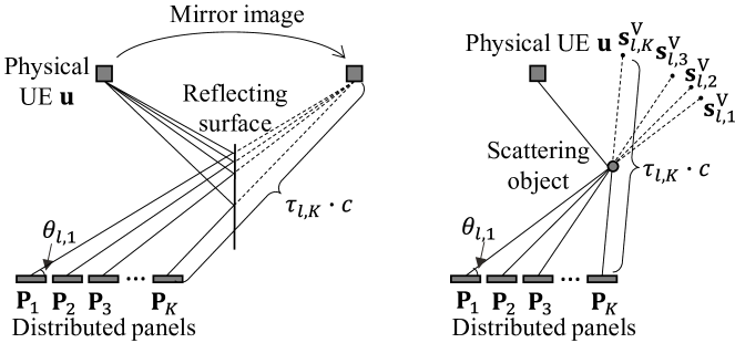
To identify the reflected MPCs, first, given an MPC from the panel -UE link with the delay and AoA , define its VS as
| (4) |
For the same single-bounce reflected MPCs from different panel-UE channels, their VSs coincide at the mirror image of the UE, as shown in Fig. 3. In the case of multi-bounce MPCs, their VSs will be the iterated mirror image of the UE. For MPCs from different links but involving other interaction mechanisms, their VSs occupy distinct positions. Inspired by these features, a Kalman filter-based framework is used to track coincident VSs from different links and subsequently identify their associated MPCs as reflected MPCs. Specifically, assuming that the VSs are static within one snapshot, the state model of is given by , where is denoted as the state processing noise with covariance matrix . The measurement/observation model is expressed as , where and are the locations of the measured VS and the measurement noise with the covariance matrix , respectively. Given from the panel ()-UE link, the predicted VS and error covariance matrix at panel -UE link are obtained by and , respectively. Then, data association between the predicted and the measured is performed. The mutual minimum distance method [17] is exploited here. Specifically, the distance between any and is calculated as . Only if a predicted VS and a measured VS are the mutually closest ones, they are tracked as the same VS. After determining the observed for , the Kalman update procedure is performed as
| (5) |
| (6) |
| (7) |
where , , represent the Kalman gain, updated error covariance matrix, and updated VS from the panel -UE link, respectively. Finally, the reflected MPCs are determined by finding whose VSs that are tracked based on the above framework. At the same time, the location of the VS is estimated iteratively.
IV Results and Analysis
In this section, the characteristics of MPCs in measured channels are investigated in terms of their interaction order and interaction mechanisms.
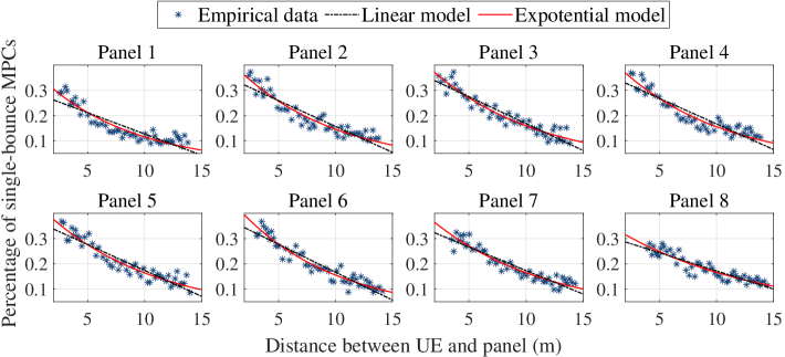
The percentage of single-bounce MPCs in different panel-UE links is shown in Fig. 4. The results in all links exhibit a consistent trend: The percentage decreases with increasing communication distance between the UE and the panels. It is reasonable since a longer communication distance makes an MPC less likely to reach the receiver through a single interaction, i.e. the possibility of experiencing multiple interactions is higher. Moreover, during the movement of the UE, the measured of all links is below 0.4. This indicates that a significant part of the MPCs in the channels are multi-bounce, exhibiting the complex scattering environment of the measured scenario. The relationship between the measured and is further fitted with linear and exponential models. The resulting fitting parameters and the R-squared () are summarized in Table I. From the results for the same link, the exponential model yields a larger , suggesting that the exponential model is preferable to characterize the relationship between and in the measured channels. It should be noted that more measurements may be needed, particularly at larger distances, to further validate this trend.
| Linear model | Exponential model | |||||
|---|---|---|---|---|---|---|
| Panel | ||||||
| 1 | -0.017 | 0.296 | 0.786 | 0.388 | -0.121 | 0.883 |
| 2 | -0.017 | 0.362 | 0.854 | 0.452 | -0.113 | 0.914 |
| 3 | -0.021 | 0.381 | 0.9 | 0.459 | -0.106 | 0.924 |
| 4 | -0.020 | 0.369 | 0.851 | 0.458 | -0.101 | 0.914 |
| 5 | -0.021 | 0.379 | 0.876 | 0.456 | -0.108 | 0.924 |
| 6 | -0.022 | 0.389 | 0.895 | 0.463 | -0.104 | 0.914 |
| 7 | -0.019 | 0.360 | 0.884 | 0.497 | -0.116 | 0.916 |
| 8 | -0.014 | 0.315 | 0.840 | 0.445 | -0.099 | 0.925 |
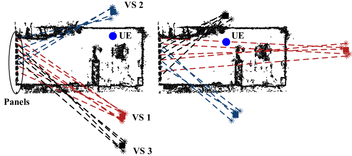
For the MPC interaction mechanisms in the measured channels, Fig. 5 illustrates examples of the reflected MPCs at snapshots 15 and 29, overlaid on the captured Lidar point cloud. The measured and estimated VS of the MPCs are represented by ‘*’ and square, respectively. For better visualization, the figure omits the reflected MPCs interacting with the ceiling and the floor. It can be found that the side walls of the room contribute with dominant reflections to the channels. Furthermore, multi-bounce reflections are observed, e.g., VS 3 in the left-hand figure, which is postulated as a mirror image of the UE as a second-order reflection. Different reflected MPCs are observed in different snapshots, which indicates that the channels are dynamic due to the movement of the UE. In addition, the consistent geometry relationship between the estimated VSs and the UE position validates the performance of the presented MPC interaction mechanism identification framework.
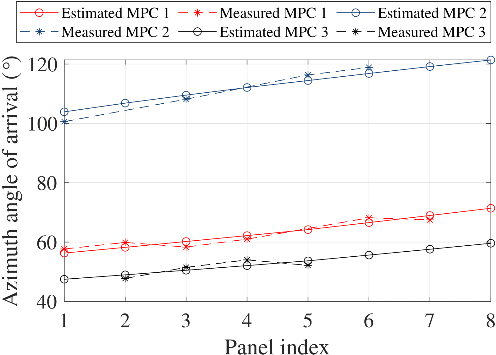
Furthermore, the azimuth AoAs of the reflected MPCs at snapshot 15 are shown in Fig. 6. For clarity, MPC 1, MPC 2, and MPC 3 refer to the MPCs associated with the VS 1, VS 2, and VS 3 in Fig. 5, respectively. The AoAs of ‘measured’ MPCs are the results directly extracted from the measurements based on the SAGE algorithm, while the AoAs of ‘estimated’ MPCs represent the results mapped from the estimated VSs. As expected, different panels are found to observe different angles of the same VS, indicating the spherical wavefront of the MPC propagation. Moreover, the birth-and-death process of the MPCs is observed in the measured channels, i.e., some MPCs are only visible for part of the panels, and their lifetimes vary across the distributed panels due to the complex scattering environment. The good fit between the estimation results and the measurement data further validates the performance of the proposed framework.
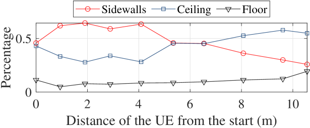
Finally, the spatial distribution of the reflected MPCs as the UE moves is shown in Fig. 7. In the early stage of the UE movement, the highest percentage of reflected MPCs is observed from the sidewalls. When the UE moves towards the panels, the percentage of reflected MPCs from the ceiling is increasing. In the end of the UE movement, more than half of the reflected MPCs originate from the ceiling. This can be explained by that a shorter propagation distance, the possibility of MPCs interacting with the metal lamps hanging from the ceiling is higher. The dynamic distribution of the reflected MPCs indicates that the MPC gain and, consequently, the channels are varying with the movement of the UE.
V Conclusions
In this letter, an indoor distributed massive MIMO channel measurement campaign has been performed. The MPC characteristics of the channels have been investigated, focusing on the order of the interaction and the interaction mechanisms of the MPCs. The results indicate that the percentage of single-bounce MPCs in the measured channels are negatively correlated with the communication distance, which is well-modeled by an exponential distribution. In addition, both the spherical wavefront and the birth-and-death process of the MPCs have been observed over the distributed panels. Finally, the distribution of the reflections is observed to be time-varying. The findings provide valuable insights into MPC propagation behavior in indoor distributed massive MIMO channels, necessary for modeling of the channels.
References
- [1] H. Q. Ngo, A. Ashikhmin, H. Yang, E. G. Larsson, and T. L. Marzetta, “Cell-free massive MIMO versus small cells,” IEEE Trans. Wireless Commun., vol. 16, no. 3, pp. 1834–1850, Mar. 2017.
- [2] H. A. Ammar, R. Adve, S. Shahbazpanahi, G. Boudreau, and K. V. Srinivas, “User-centric cell-free massive MIMO networks: A survey of opportunities, challenges and solutions,” IEEE Commun. Surveys Tuts., vol. 24, no. 1, pp. 611–652, 1st Quart., 2022.
- [3] D. Lschenbrand, M. Hofer, L. Bernad, S. Zelenbaba, and T. Zemen, “Towards cell-free massive mimo: A measurement-based analysis,” IEEE Access, vol. 10, pp. 89232–89247, 2022.
- [4] Y. Zhang et al., “Cell-free massive MIMO channels in an urban environment–measurements and channel statistics,” IEEE Trans. Wireless Commun., submitted for publication, https://arxiv.org/pdf/2406.01850.
- [5] T. Choi, P. Luo, A. Ramesh, and A. F. Molisch, “Co-located vs distributed vs semi-distributed MIMO: Measurement-based evaluation,” in Proc. 54th Asilomar Conf. Signals, Syst., Comput., Nov. 2020, pp. 836–841.
- [6] C. Nelson, S. Willhammar, and F. Tufvesson, “A measurement-based spatially consistent channel model for distributred MIMO in industrial environments,” IEEE Trans. Wireless Commun.,, submitted for publication. https://arxiv.org/abs/2412.12646.
- [7] Y. Xu, M. Sandra, X. Cai, S. Willhammar, F. Tufvesson, “Spatial seperation of closely-spaced users in measured distributed massive MIMO channels,” in Proc. IEEE SPAWC’24, Lucca, Italy, 2024, pp. 1–6.
- [8] Y. Xu, M. Sandra, X. Cai, S. Willhammar, F. Tufvesson, “Characterization of non-wide-sense stationarity for distributed massive MIMO channels,” in Proc. IEEE EuCAP’25, accepted for publication.
- [9] W. Fan et al., “Near-Field channel characterization for mid-band ELAA system: sounding, parameter estimation, and modeling,” IEEE Commun. Mag., submitted for publication. https://arxiv.org/abs/2405.06159.
- [10] Z. Yuan, J. Zhang, V. Degli-Esposti, Y. Zhang, and W. Fan, “Efficient ray-tracing simulation for near-field spatial non-stationary mmWave massive MIMO channel and its experimental validation,” IEEE Trans. Wireless Commun., vol. 23, pp. 8910–8923, Aug. 2024.
- [11] P. Tang et al., “XL-MIMO channel measurement, characterization, and modeling for 6G: a survey,” Front. Inf. Technol. Electron. Eng, vol. 25, pp. 1627–1650, Nov. 2024.
- [12] F. Fuschini, M. Zoli, E. M. Vitucci, M. Barbiroli, and V. Degli-Esposti, “A study on millimeter-wave multiuser directional beamforming based on measurements and ray tracing simulations,” IEEE Trans. Antennas Propag., vol. 67, no. 4, pp. 2633–2644, Apr. 2019.
- [13] X. Li, E. Leitinger, M. Oskarsson, K. Åström, and F. Tufvesson, “Massive MIMO-based localization and mapping exploiting phase information of multipath components,” IEEE Trans. Wireless Commun., vol. 18, no. 9, pp. 4254–4267, Sep. 2019.
- [14] M. Sandra, C. Nelson, X. Li, X. Cai, F. Tufvesson, and A. J. Johansson, “A wideband distributed massive MIMO channel sounder for communication and sensing“, IEEE Trans. Antennas Propag., accepted for publication, doi: 10.1109/TAP.2025.3537292.
- [15] X. Yin, B. H. Fleury, P. Jourdan, and A. Stucki, “Polarization estimation of individual propagation paths using the SAGE algorithm,” in Proc. PIMRC’03, Beijing, China, Sept. 2003, pp. 1795–1799.
- [16] Y. Xu, M. Sandra, X. Cai, S. Willhammar, and F. Tufvesson, “Interacting Object-Enabled Clustering and Characterization of Distributed MIMO Channels”, IEEE Trans. Wireless Commun., submitted for publication.
- [17] X. Cai et al., “Dynamic channel modeling for indoor millimeter-wave propagation channels based on measurements,” IEEE Trans. Commun., vol. 68, no. 9, pp. 5878–5891, Sep. 2020.