Exotic Quantum States in Spin-1 Bose-Einstein Condensate with Spin-Orbit Coupling in Concentric Annular Traps
Abstract
We explore the exotic quantum states emerging in the ground state (GS) of a strongly-correlated spin-1 Bose-Einstein condensate confined in two-dimensional concentric annular traps with a spin-orbit coupling (SOC). In the antiferromagnetic case, the GS density manifests various patterns of distributions, including facial-makeup states, petal states, topological fissure states, multiple-half-ring states and property-distinguished vertical and horizonal stripe states. We notice a peculiar phenomenon of density-phase separation in the sense that the variations of density and phase tend to be independent. In ferromagnetic case, the GS exhibits a semi-circular or half-disk status of density embedded with vortices and anti-vortices. The spin distribution can self-arrange into an array of half-skyrmions and we also find a half-antiskyrmion fence separating vortex-antivortex pairs. Our study indicates that one can manipulate the emergence of exotic quantum states via the interplay of the SOC, interaction and potential geometry and the abundant state variations might also provide potential resources for quantum metrology.
I Introduction
Spin-orbit coupling (SOC) has a wide relevance in physical systems such as condensed matter Krieger et al. (2024); Jiang et al. (2017); Manchon et al. (2015); Bychkov and Rashba (1984); Dresselhaus (1955), nanosystems Gentile et al. (2022); Ying et al. (2020, 2017, 2016); Nagasawa et al. (2013), light-matter interactions Ying (2022a, b, 2023a, 2023b, 2024a) and cold atoms Liu et al. (2025, 2024a); Chen et al. (2024); Fang et al. (2023); Huang et al. (2019); Galitski and Spielman (2013); Li et al. (2012); Lin et al. (2011). The competition and interplay of SOC with spin interaction, density interaction, external potential, and geometry may induce exotic quantum states and novel quantum phases of matter.
Among these relevant systems a highly-controllable system is ultra-cold atomic gas Li et al. (2012); Lin et al. (2011); Galitski and Spielman (2013). The alkali metal atomic gases in the optical trap are bound to hyperfine energy states, forming a spinor Bose-Einstein condensate (BEC) Ho (1998); Görlitz et al. (2003). Spinor BEC provides more opportunities to study various interesting topological excitations due to the release of internal spin degrees of freedom Liu et al. (2017); Chen et al. (2018); Baio et al. (2024); Seo et al. (2016); Orlova et al. (2016); Liu et al. (2024b); Yu and Blakie (2022); Saboo et al. (2024). Through the application of the Feshbach resonance technology, one can continuously adjust the s-wave scattering length between atoms to accurately control the internal and external degrees of freedom of atoms Sawyer et al. (2017); Shi et al. (2012); Zhang et al. (2021). Such a high controllability of BEC provides an ideal platform to explore novel physical properties and exotic quantum states Anderson et al. (1995); Zhao et al. (2017); Horvath et al. (2024).
In particular, synthetic spin-orbit coupling (SOC) can be realized in ultracold atomic spinor BEC systems Lin et al. (2011); Galitski and Spielman (2013); Wu et al. (2016); Campbell et al. (2016). SOC plays a crucial role in many important condensed matter phenomena Zhang et al. (2012a); Hou et al. (2024); Chiu et al. (2020). Still, more varieties of properties stem from the interplay of SOC with density and spin interactions as well as the geometry and dimensions of the external potential, including plane-wave phase and stripe phase Chiu et al. (2020); Huang et al. (2019), solitons Fang et al. (2023); Ohi et al. (2022); Gautam and Adhikari (2018); Kartashov et al. (2013); Li et al. (2017a), vortices Li et al. (2023); Peng et al. (2020); Wang et al. (2021a), supersolids Li et al. (2017b); Sachdeva et al. (2020), lattice phases Sinha et al. (2011), skyrmions Wang et al. (2021b) and so forth. Regarding the shape of the external potential, different types of potential can be considered within the current experimental capability, such as the harmonic trap Mujal et al. (2020); Liu et al. (2025); Shirley et al. (2014), optical lattice Sun et al. (2016); Salerno et al. (2016); Kühn and Judd (2013), toroidal trap Wang et al. (2017); White et al. (2017); Kunimi and Danshita (2019); Zhang et al. (2022); Liu et al. (2022); Roussou et al. (2018), double wells Li et al. (2024), vertically or concentrically coupled double-ring traps Zhang et al. (2012b).
When most studies have been concentrated on the conventional SOCs including Rashba and Dresselhaus SOCs Liu et al. (2024a); Chen et al. (2024); Meng et al. (2016); Li et al. (2012); Liu et al. (2025); Wu et al. (2016); Campbell et al. (2016); Galitski and Spielman (2013); Anderson et al. (2013); Lin et al. (2011), an unconventional SOC is introduced recently Liu et al. (2025) for spin-1 BEC in a harmonic potential, which induces a novel topological structure as vortex molecule. A deeper study is desirable for the interplay of the unconventional SOC with the density/spin interactions and the potential geometry. Especially, one may expect that more exotic quantum states may arise when the interplay situation is affected by the potential geometry.
In the present work we consider a spin-1 BEC with the unconventional SOC in concentric annular traps which spatially creates a more stimulating situation for the interplay of the SOC with the density interaction and spin interaction. We find that such a change of potential geometry induces abundant exotic quantum states in the ground state (GS). Indeed, in the antiferromagnetic case, the GS density manifests various patterns of distributions, including petal states, facial-makeup states, topological fissure states, multiple-half-ring states and property-distinguished vertical and horizontal stripe states. In a spin-1 component we notice a peculiar phenomenon of density-phase separation. In ferromagnetic case, the GS exhibits semi-circular and half-disk states embedded with vortices and anti-vortices. We also find states with a self-arranging array of half-skyrmions and half-antiskyrmion fence separating vortex-antivortex pairs.
This paper is organized as follows. In Sec. II, the model of the spin-1 BEC with the unconventional SOC confined in concentric annular traps is introduced, and the numerical method is briefly given. In Sec. III we address the GS structure in antiferromagnetic case. The effects of SOC and the influence of the interaction ratio are analyzed, various patterns of distributions are demonstrated and the phenomenon of density-phase separation revealed. In Sec. IV we discuss the GS in ferromagnetic case. Density distribution style different from the antiferromagnetic case are demonstrated. In particular, topological defects, including vortices and anti-vortices, array of half-skyrmions and half-antiskyrmion fence, are unveiled. Finally, Sec. V gives a summary of the main results.
II Model and method
We consider a quasi-two-dimensional spin-1 BEC with the unconventional SOC confined in concentrically coupled annular traps. Within the mean-field approximation, the effective Hamiltonian can be written as , with
| (1) |
where denotes the order parameter of BEC, subject to the normalization condition , with being the total particle number. is the mass of atom and , where , is the total condensate density of all spin components. is the external potential, which will be given below. Here the effective space is restricted to the and dimensions, with the position denoted by , while the dynamics in the z-direction is frozen by a strong confinement. The unconventional SOC with coupling strength takes the form of Liu et al. (2025), with being the vector of the spin-1 matrices. The unconventional SOC contains both orthogonal Bychkov and Rashba (1984) and parallel Krieger et al. (2024) spin-momentum couplings and may be synthesized in ultracold atomic spinor BEC systems Liu et al. (2025); Lin et al. (2011); Galitski and Spielman (2013); Wu et al. (2016); Campbell et al. (2016). The coefficients and in represent the strengths of density-density and spin-exchange interactions respectively, while is the spin density vector.
The condensate can be described by the Gross-Pitaevskii equation
| (2) |
where and . In order to facilitate numerical treatments, the units for energy, length, time, and are rescaled by , , and , respectively. With these units, the coefficients become and , where and are the s-wave scattering lengths in the total spin channels. The equation becomes dimensionless by setting .
We consider the external trapping potential
| (3) |
with being the distance from the origin as in the polar coordinates. The two overlapping parabolas with respect to , characterized by frequencies and and the bottom locations and , finally form two concentric annular traps in the - plane. Furthermore, to ensure that the product of the ’width’ and the radius of each annulus remains comparable, one can set the condition . In this paper, we take and with being the oscillator length, and . To obtain the GS of the system, the Gross-Pitaevskii energy, given by
| (4) |
as a functional of , is minimized with the aid of the imaginary-time method.
III Antiferromagnetic Case
In this part, we consider the GS structure in antiferromagnetic case with . In various patterns of density distributions, some exotic quantum states emerge, including facial-makeup states, topological fissure states, property-distinguished vertical and horizontal stripe states. A peculiar tendency of density-phase separation is found in the sense that the variations of density and phase tend to be independent.
III.1 Density distributions and exotic quantum states
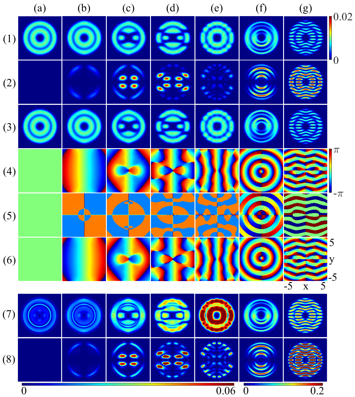
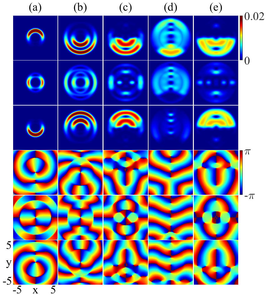
Fig. 1 shows the GS in varying the strength of SOC from zero (a) to a large one (g) at fixed interactions . Here in Fig. 1 the upper three rows (1-3) display the density distributions for the spin components (1), (2), (3), the middle three rows (4-6) show the corresponding phase () of and the lower two rows (7,8) represent the local kinetic energy for (7) and (8).
In the density distributions in Fig. 1(1-3), with the increasing SOC the components change from inner and outer rings (a), deformed outer ring (b), broken inner ring (c), both broken rings (d), reconnected inner ring and more fragmented outer ring (e), rings with fissures (f), to rings broken into horizontal stripes (g). In particular, the fissures in the upper and lower parts of both rings in case (f) actually change the topological structure of the rings, just like the number of holes in an object is changed. But the topological scenario is not only this simple geometric topology in the density. In fact, we further find that such density-fissure state is accompanied with spin vortices or antivortices, we leave the discussion in Section IV.3.1 together with the ferromagnetic case. Thus, the fissures actually change the topology both in the density and spin distributions.
The density distribution of [row (2) in Fig. 1] starts with an empty filling (a), then appears as broken outer ring (b), petals in inner part with broken outer ring (c), extended petals to outer part and more fragmented outer ring (d), two size sets of inner petals overlapping with outer fragmented outer ring (e), multiple half rings (f) and stripe state (g). The vanishing distribution in (a) minimizes the spin-spin interaction energy as the term in Eq. (4) is positive. The half rings in (f) fill in the density fissures of components to reduce the energy of density-density interaction. And the stripes in (d) are dislocated from those in components to minimize the energy of density-density interaction as well.
Coincidentally, the broken ring structures in the components appear like a human face in Balaclava (c) and a head shot of a person with headphones (d). The mixed-petal structure of case (e) in the component also looks like a facial-makeup of Peking opera [clearer view in row (8)]. Such coincidences also occur in lighter-matter interactions where the effective SOC produces spin-winding profiles in formal or spiritual similarity with humans or animals Ying (2023b), reflecting another interesting side of SOC in quantum effects.
We also notice that the ring breakings or crackings generally occur around the places where the local kinetic energy is vanishing, as compared with the (7,8) rows in Fig. 1. In fact, a large would enhance the effect of the momentum-dependent SOC which actually exchanges the spin components. Otherwise, a vanishing might weaken such a component exchange so that the density is not transferred, e.g., from to , thus leaving the vanishing density (cracking places) in the distribution.
III.2 Phase distributions and symmetry breaking
The phase distribution of [row (4)] in Fig. 1 evolves from homogenous structure (a), shape of two vertical long breads (b), anti-symmetric bow ties in angle brackets (c), bow ties in distorted braces (d), vertical stripes (e), eccentric rings (f), to horizontal stripes (g).
During these variations the rotational symmetry in (a) in the absence of SOC is broken into reflection symmetry (antisymmetric) in the ( direction in (b-d) in the presence of SOC, the -reflection symmetry is further broken in (f) as the rings are eccentric. The -reflection symmetry tend to recover in (g) but in an antisymmetric way. The component [row (5)] has parity symmetry, while the components are antisymmetric in parity within themselves and symmetric under spin exchange.
III.3 A tendency of density-phase separation
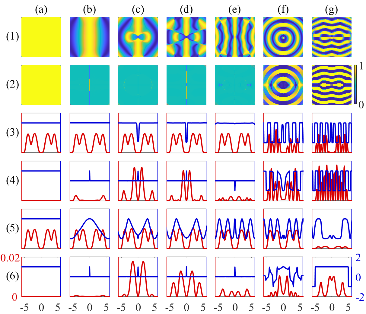
A closer comparison of the phase and density draws our attention to a peculiar phenomenon of density-phase separation that the variations of density phase tend to be independent. In Fig. 1(4-6) we have plotted the phase within the range of , while a spurious boundary of phase jump may arise even if the phase continuously crosses . On the other hand, it would be also necessary to distinguish a nontrivial phase variation of odd times of from even times Ying et al. (2020, 2017, 2016); Nagasawa et al. (2013). For these reasons we replot the phase by in Fig. 2, with in the first row and in the second row. From the cases (a)-(e) in the second row of Fig. 2 we see that the amplitude of remains flat within the ring trap range despite that the various patterns of density distributions are changing, which indicates some degree of independence between the variations of the density and phase. Line plots in Figs. 2(4a-4e) and 2(3a-3e) by a fixed value of confirm such a density-phase separation, as basically keeps in a flat status while the density are varying. In the other direction by fixing a position we also see such a tendency of density-phase separation in Figs. 2(6a-6e) for . Although some phase variation comes up in Figs. 2(5a-5e) for as well as in Figs. 2(6f-6g) for , the correlation with the density variation is still not obvious, as reflected by the unmatched peak numbers.
III.4 A difference in vertical and horizontal-stripe states
We have seen two orientations of the stripe states in the phase of the components, with vertical stripes in 1(e4) and horizontal stripes in 1(g4). Still, despite of the stripe-structure similarity of the phase in the , they are distinguished in the density of all spin components and the phase of the component. The horizontal one forms a stripe structure in the density as well, while the vertical one does not show any stripe sign in the density distribution of all the spin components as in 1(g), the latter also being a manifest of density-phase separation. Furthermore, when in the horizontal one the phase of the component follows the stripe structure of the components, the vertical one remains in a flat amplitude of phase in the component as in 2(e) and 3(f). Such a difference demonstrates the different roles of the unconventional SOC in the different directions.
III.5 Influence of interactions
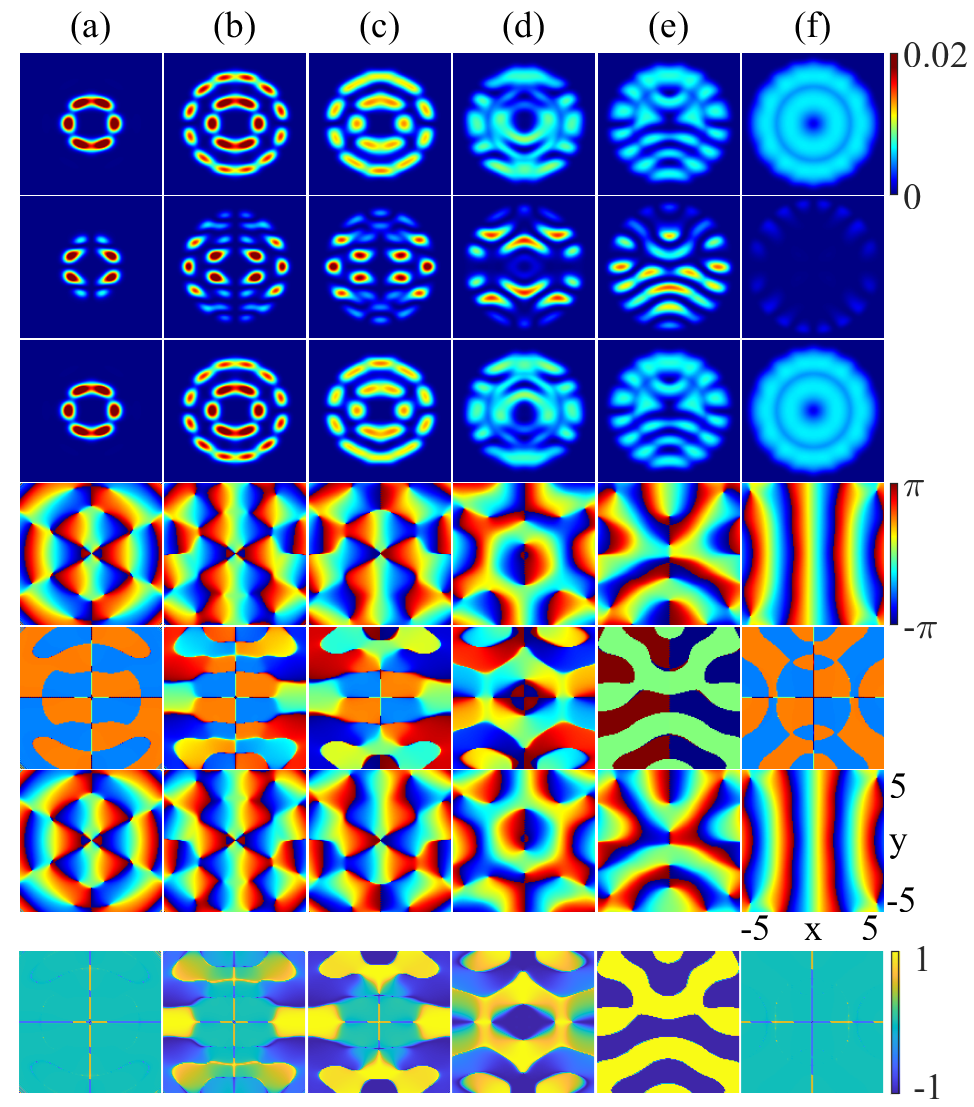
In previous sections we have addressed the effect of the SOC in inducing the exotic quantum states, here we examine the influence of the interactions. Fig. 3 presents the variations of the density (upper three rows) and phase (lower three rows) distributions in varying the ratio between the density interaction and spin interaction at a fixed SOC. When we vary from a small value [ in Fig. 3(a)] to a large one [ in Fig. 3(f)] the density distribution changes from structures of a single broken inner ring (a), inner and outer broken rings (b,c), overlapping inner and outer broken rings (d), coexisting petals and stripes (e), to be a structure of two continuous rings in the components with vanishing inner ring and a weak outer fragmented ring in the component. Such variations are reasonable as the strengthened density-density interaction tends to extend the density distribution to reduce its positive energy, while the interplay of the interactions with the SOC induces the nontrivial variations.
We also see that the reflection symmetry with respect to the axis within a same component is basically preserved in small values of as in Fig. 3(a-c) while it is broken in the components in Fig. 3(d) and in all spin component in Fig. 3(e). The symmetry tends to recover when the density turns to unbroken rings in larger as in Fig. 3(f). The phase is more sensitive to check the symmetry breaking, as we can see from Fig. 3(c) the phase reflection anti-symmetry in the components is already broken obviously even when the density still basically preserves the reflection symmetry. Although in Fig. 3(c) and 3(d) the anti-reflection symmetry is broken within a same component for , it is holding if the spin is reversed simultaneously. Such a spin-exchange-associated reflection is also broken in Fig. 3(e) both in the desnity and phase.
Furthermore, we recall the afore-mentioned tendency of density-phase separation in the small- case [Fig. 3(a)] and large- case [Fig. 3(f)] as shown by the cosine plots of the phase for the component in the bottom row. We indeed see again here that the phase amplitude becomes flat when the density has a non-trivially inhomogeneous distribution.
IV Ferromagnetic case
In this part, we discuss the ferromagnetic case with . Differently from the antiferromagnetic case, here we will see semi-circular or half-disk status of density embedded with vortices and anti-vortices. We also find other exotic quantum states including self-arranging array of half-skyrmions and half-antiskyrmion fence in spin distribution.
IV.1 Semi-circular distribution in varying SOC
We first check the GS structure in varying the SOC at fixed density-density and spin-spin interactions.
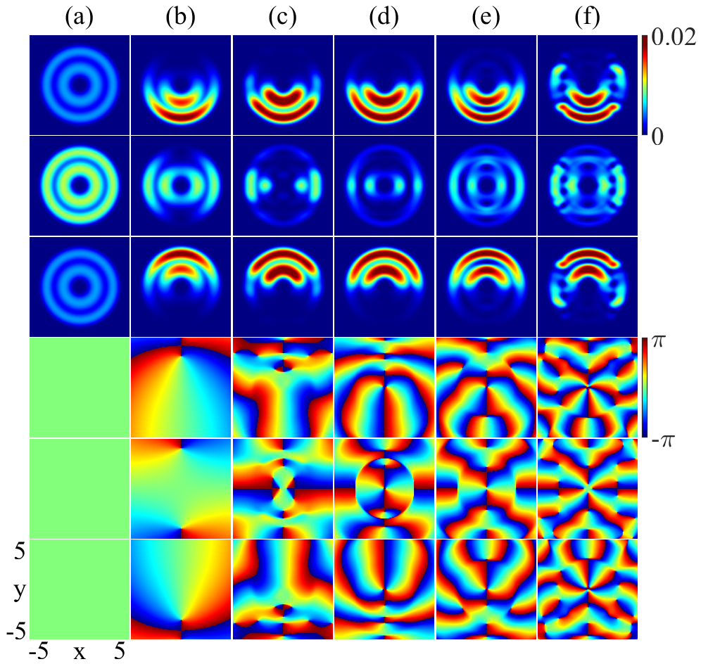
In the absence of SOC, the density appears with a structure of two concentric rings in all components, as in Fig. 4(a). Here, in contrast to the vanishing density in the antiferromagnetic case, the component has a finite density and the density is even larger than the components.
Turning on the SOC, in the component the density tends to gather around the axis, while away from the axis the density is smaller, as in Figs. 4(b) and 4(c). With an increased strength of SOC in Figs. 4(c) and 4(d), we see that fissures emerge in the weak parts of density rings around the axis. In a larger SOC, the outer and inter rings tend to get connected, and the fissures evolve into holes as in Fig. 4(e). With further region connection more density holes form also away from the axis, as in Fig. 4(f).
On the other hand, in the components, the density distributions become half-ring-like in the presence of SOC, with lower half rings for and upper half rings for , as in Figs. 4(b)-(e). In a large SOC, the density holes emerge too, also vertically but displaced from those of components, together with the remaining density arches forming a clown-face like distribution.
We also plot the phase in the lower three rows of Fig. 4. The phase evolves from a uniform distribution in the the absence of SOC into a complicated distribution even when the density basically remains in a half-ring structure in the components, which also manifests a density-phase separation in some sense.
IV.2 Influence of interaction ratio
The variation of the GS in different interaction ratio is presented in Fig. 5. With the increase of , the density distribution in changes the shape from an inner half ring (a), inner and outer half rings (b), inner and outer arcs (c), to coexisting arcs and half disk with holes (d). We also find a state of half disk with dual hole and island (e) by tuning a bit the SOC at the final interaction ratio, which more confirms the manipulation effect by the interplay of the SOC and interactions.
In the component, the density distribution varies from inner structure with left-right arcs and top-bottom fissures (a), inner and outer structures with left-right arcs and top-bottom fissures (b), astronaut-helmet-like shape (c), corner-broken disk (d), to coexisting half disks and island array (e).
IV.3 Topological defects in spin distribution
The spin texture can be extracted by Mizushima et al. (2004); Kasamatsu et al. (2005)
| (5) |
where label the three spin directions. Topological defects may arise in the spin texture in our system. The spatial structure of the topology of the system can be described by the topological charge density
| (6) |
where and , while its integral
| (7) |
characterizes the topological charge Nagaosa and Tokura (2013).
IV.3.1 Vortices and antivortices
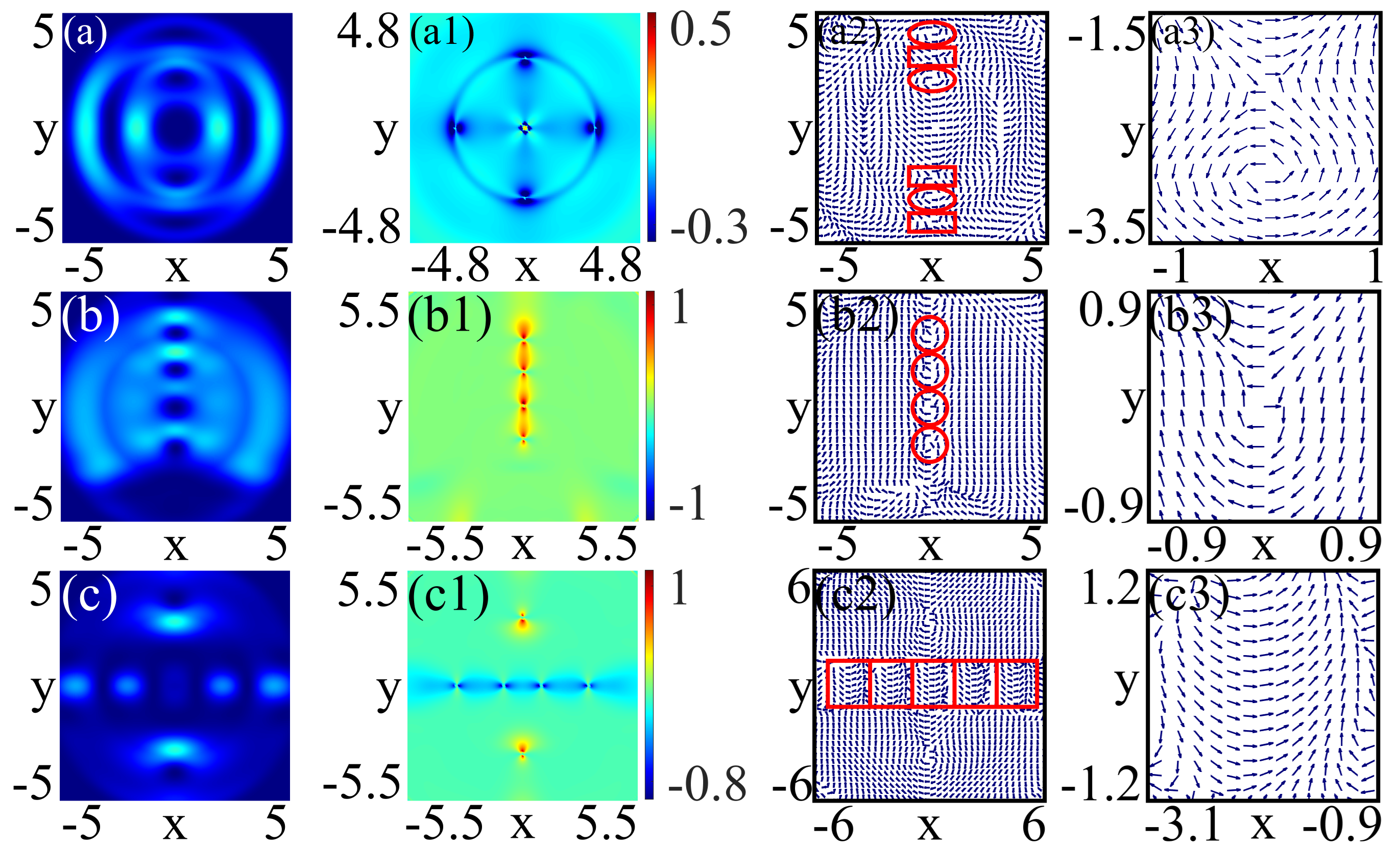
We find that vortices and antivortices emerge in all the states with half-ring structure. The case with a weak SOC in Fig. 4(b) has one vortex and one antivortex, while their number increases when the component has fissures and holes in the density as the SOC is enhanced. Indeed the vortices and antivortices form at the density valleys and peaks of the component. In Fig. 6(a2), we illustrate the spin projection on the - plane for the case in Fig. 5(b) [similar to Fig. 4(e)]. The vortices are marked by the ellipses and antivortices by rectangles in Fig. 6(a2) and the structure of the vortex and antivortex can be seen more clearly in a close-up plot in Fig. 6(a3).
We notice two features about the vortex locations in our system: (i) These vortices and antivortices are distributed antisymmetrically with respect to the axis in the sense that if a vortex appears at position an antivortex will form at position . (ii) These vortices and antivortices are located at the position density valleys (holes) and peaks of the component, as compared with the density plot in Fig. 6(a). It should be noted that the valleys may correspond to density peaks in the components due to the fissure or hole dislocations in reducing the energy of the density-density interaction.
It should be mentioned that one can also find vortices and antivortices in the ring-fissure state [Fig.1(f)] and the stripe state [Fig.1(g)] in the antiferromagnetic case addressed in Section III, with a similar location tendency as in the above features. Indeed, the ring-fissure state has a series of vortices (antivortices) on the positive-(negative-) axis, while in the stripe state more vortices and antivortices are dispersedly distributed at the wavy places of the stripes.
These observations indicate that the locations of vortices and antivortices can be manipulated by tuning the potential geometry, SOC and interactions.
IV.3.2 Self-aligning half-skyrmion array
The spin texture can also self-arranges into an array of half-skyrmions. We illusrate such a state in Fig. 6(b2) where the half-skyrmion array is marked by the circles. Such a half-skymion alignment is associated with the hole arrray in the density disk in Fig. 5(d) with the component replotted in Fig. 6(b) for better position correspondence with the half-skyrmions. A close-up view of the half-skyrmion spin structure is presented in Fig. 6(b3).
IV.3.3 Self-arranging half-antiskyrmion fence
We also find a half-antiskyrmion fence that forms horizontally along the -axis and separates two vortix-antivortex pairs located at the positive and negative -axes, as shown in Fig. 6(c2) where each square marks a half-antiskyrmion. The half-antiskyrmions have a minus fractional topological charge
| (9) |
Such a half-antiskyrmion fence is associated with the density distribution of coexisting half disks and island array in Fig. 5(e), as compared with density in the component replotted in Fig. 6(c) for better position correspondence. The corresponding topological charge density is given in Fig. 6(c1) while a zoom-in plot of a half-antiskyrmion in the fence is displayed in Fig. 6(c2).
V Conclusions and discussions
We have systematically investigated a spin-1 BEC with an unconventional SOC in two concentric annular traps, the GS of which manifests various exotic quantum states from the distributions of the density, phase and spin texture.
In the antiferromagnetic case, the GS density exhibits various patterns of distributions, including ring state, petal states, facial-makeup states, topological fissure states, multiple-half-ring states, property-distinguished vertical and horizonal stripe states. In particular, the fissures in the ring density not only bring changes in the geometric topology of the density but also are topologically associated with appearance of spin vortices and antivortices. In the strength increase of the SOC, the symmetry is broken in different degrees, with respect to the rotation symmetry, reflection symmetry, parity symmetry, within a same spin component or simultaneously with a spin exchange. The cracking places in density ring fragmentation are related with vanishing local kinetic energy which locally weakens the effect of the SOC. We also notice a peculiar phenomenon of density-phase separation in the sense that the variations of density and phase tend to be independent.
In ferromagnetic case, the GS displays density distributions different from the antiferromagnetic case by semi-circular structure, corner-broken disk with aligned holes, or coexisting half disk and island array. The spin distribution is embedded with vortices and anti-vortices. The spin distribution can self-arranges into an array of half-skyrmions aligning vertically. A horizontal half-antiskyrmion fence is also found separating vortex-antivortex pairs.
The topological defects generally appear around the density valleys and peaks. In antiferromagnetic case vortices can form on the axis in ring-fissure states and more dispersedly in wavy places of stripe states, while in ferromagnetic case the topological defects are located on the or axis. Indeed, vortices and anti-vortices always can be found on the axis in semicircular states in ferromagnetic case. Half-skyrmion array along the axis and half-antiskyrmion fence along the axis emerge in the strong overlapping of density rings, as driven by a large ratio of density interaction and spin interaction in the presence of the SOC. These observations indicate that the unconventional SOC may be helpful to create stripe states and locate the positions of topological defects.
These exotic quantum states in the various distribution patterns in the density, phase and spin texture with topological structures are the results of the interplay of the SOC, ratio of density interaction and spin interaction and the geometry of potential. Our study implies that one can manipulate the emergence of exotic quantum states via these factors, which is feasible due to the high controllability of cold atom systems Li et al. (2012); Lin et al. (2011); Galitski and Spielman (2013); Wu et al. (2016); Campbell et al. (2016); Huang et al. (2019); Anderson et al. (2013). As a final remark, the abundant state variations might also provide potential resources for quantum metrology Rams et al. (2018); Garbe et al. (2020); Montenegro et al. (2021); Ilias et al. (2022); Ying et al. (2022); Hotter et al. (2024); Ying (2024b, 2025) by exploiting the change of the GS wave function for measurement of parameters Braunstein and Caves (1994); Rams et al. (2018); Ying et al. (2024).
Acknowledgements.
This work was supported by the National Natural Science Foundation of China (Grants No. 12474358, No. 11974151, and No. 12247101).References
- Krieger et al. (2024) J. A. Krieger, S. Stolz, I. Robredo, K. Manna, E. C. McFarlane, M. Date, B. Pal, J. Yang, E. B. Guedes, J. H. Dil, et al., Nature communications 15, 3720 (2024).
- Jiang et al. (2017) W. Jiang, G. Chen, K. Liu, J. Zang, S. G. te Velthuis, and A. Hoffmann, Physics Reports 704, 1 (2017).
- Manchon et al. (2015) A. Manchon, H. C. Koo, J. Nitta, S. M. Frolov, and R. A. Duine, Nature Materials 14, 871 (2015).
- Bychkov and Rashba (1984) Y. A. Bychkov and E. I. Rashba, J. Phys. C 17, 6039 (1984).
- Dresselhaus (1955) G. Dresselhaus, Phys. Rev. 100, 580 (1955).
- Gentile et al. (2022) P. Gentile, M. Cuoco, O. M. Volkov, Z.-J. Ying, I. J. VeraMarun, D. Makarov, and C. Ortix, Nature Electronics 5, 551 (2022).
- Ying et al. (2020) Z.-J. Ying, P. Gentile, J. P. Baltanás, D. Frustaglia, C. Ortix, and M. Cuoco, Phys. Rev. Res. 2, 023167 (2020).
- Ying et al. (2017) Z.-J. Ying, M. Cuoco, C. Ortix, and P. Gentile, Phys. Rev. B 96, 100506(R) (2017).
- Ying et al. (2016) Z.-J. Ying, P. Gentile, C. Ortix, and M. Cuoco, Phys. Rev. B 94, 081406(R) (2016).
- Nagasawa et al. (2013) F. Nagasawa, D. Frustaglia, H. Saarikoski, K. Richter, and J. Nitta, Nat. Commun. 4, 2526 (2013).
- Ying (2022a) Z.-J. Ying, Adv. Quantum Technol. 5, 2100088 (2022a), [Back Cover (Adv. Quantum Technol. 1/2022): Z.-J. Ying, Adv. Quantum Technol. 5, 2270013 (2022)].
- Ying (2022b) Z.-J. Ying, Adv. Quantum Technol. 5, 2100165 (2022b).
- Ying (2023a) Z.-J. Ying, Adv. Quantum Technol. 6, 2200068 (2023a), [Front Cover (Adv. Quantum Technol. 1/2023): Z.-J. Ying, Adv. Quantum Technol. 6, 2370011 (2023)].
- Ying (2023b) Z.-J. Ying, Adv. Quantum Technol. 6, 2200177 (2023b), [Front Cover: (Adv. Quantum Technol. 7/2023), Z.-J. Ying, Adv. Quantum Technol. 6, 2370071 (2023)].
- Ying (2024a) Z.-J. Ying, Phys. Rev. A 109, 053705 (2024a).
- Liu et al. (2025) Y.-K. Liu, Y.-F. Gao, N. Yue, and S.-J. Yang, Chaos, Solitons & Fractals 191, 115854 (2025).
- Liu et al. (2024a) F.-Y. Liu, H. Triki, and Q. Zhou, Chaos, Solitons & Fractals 186, 115257 (2024a).
- Chen et al. (2024) J. Chen, D. Mihalache, M. R. Belić, X. Gao, D. Zhu, D. Deng, S. Qiu, X. Zhu, and L. Zeng, Chaos, Solitons & Fractals 186, 115325 (2024).
- Fang et al. (2023) P. Fang, J. He, R. Asgari, X. Gao, and J. Lin, Eur. Phys. J. Plus 138, 482 (2023).
- Huang et al. (2019) Y.-X. Huang, W. F. Zhuang, X.-F. Zhou, H. Pu, G.-C. Guo, and M. Gong, Phys. Rev. A 100, 053606 (2019).
- Galitski and Spielman (2013) V. Galitski and I. B. Spielman, Nature 494, 49 (2013).
- Li et al. (2012) Y. Li, L. P. Pitaevskii, and S. Stringari, Phys. Rev. Lett. 108, 225301 (2012).
- Lin et al. (2011) Y.-J. Lin, K. Jiménez-García, and I. B. Spielman, Nature 471, 83 (2011).
- Ho (1998) T.-L. Ho, Phys. Rev. Lett. 81, 742 (1998).
- Görlitz et al. (2003) A. Görlitz, T. L. Gustavson, A. E. Leanhardt, R. Löw, A. P. Chikkatur, S. Gupta, S. Inouye, D. E. Pritchard, and W. Ketterle, Phys. Rev. Lett. 90, 090401 (2003).
- Liu et al. (2017) C.-F. Liu, G. Juzeliūnas, and W. Liu, Physical Review A 95, 023624 (2017).
- Chen et al. (2018) H.-R. Chen, K.-Y. Lin, P.-K. Chen, N.-C. Chiu, J.-B. Wang, C.-A. Chen, P. Huang, S.-K. Yip, Y. Kawaguchi, and Y.-J. Lin, Physical Review Letters 121, 113204 (2018).
- Baio et al. (2024) G. Baio, M. T. Wheeler, D. S. Hall, J. Ruostekoski, and M. O. Borgh, Physical Review Research 6, 013046 (2024).
- Seo et al. (2016) S. W. Seo, W. J. Kwon, S. Kang, and Y. Shin, Phys. Rev. Lett. 116, 185301 (2016).
- Orlova et al. (2016) N. V. Orlova, P. Kuopanportti, and M. V. Milošević, Phys. Rev. A 94, 023617 (2016).
- Liu et al. (2024b) Y.-K. Liu, N. Yue, J.-J. Zhang, and S.-J. Yang, Results in Physics 56, 107263 (2024b).
- Yu and Blakie (2022) X. Yu and P. Blakie, Physical Review Research 4, 033056 (2022).
- Saboo et al. (2024) A. Saboo, S. Halder, S. Das, and S. Majumder, Physical Review A 110, 033325 (2024).
- Sawyer et al. (2017) B. J. Sawyer, M. S. Horvath, E. Tiesinga, A. B. Deb, and N. Kjærgaard, Physical Review A 96, 022705 (2017).
- Shi et al. (2012) Z.-Y. Shi, R. Qi, and H. Zhai, Physical Review A—Atomic, Molecular, and Optical Physics 85, 020702 (2012).
- Zhang et al. (2021) Y. Zhang, Y. Wang, W. Jiang, and W. Li, Physical Review A 104, 063312 (2021).
- Anderson et al. (1995) M. H. Anderson, J. R. Ensher, M. R. Matthews, C. E. Wieman, and E. A. Cornell, science 269, 198 (1995).
- Zhao et al. (2017) X. Zhao, D. A. Alcala, M. A. McLain, K. Maeda, S. Potnis, R. Ramos, A. M. Steinberg, and L. D. Carr, Phys. Rev. A 96, 063601 (2017).
- Horvath et al. (2024) M. Horvath, S. Dhar, A. Das, M. D. Frye, Y. Guo, J. M. Hutson, M. Landini, and H.-C. Nägerl, Nature Communications 15, 3739 (2024).
- Wu et al. (2016) Z. Wu, L. Zhang, W. Sun, X.-T. Xu, B.-Z. Wang, S.-C. Ji, Y. Deng, S. Chen, X.-J. Liu, and J.-W. Pan, Science 354, 83 (2016).
- Campbell et al. (2016) D. Campbell, R. Price, A. Putra, A. Valdés-Curiel, D. Trypogeorgos, and I. Spielman, Nature Communications 7, 10897 (2016).
- Zhang et al. (2012a) Y. Zhang, L. Mao, and C. Zhang, Phys. Rev. Lett. 108, 035302 (2012a).
- Hou et al. (2024) A. Hou, H. Lyu, Y. Chen, and Y. Zhang, Results in Physics , 107809 (2024).
- Chiu et al. (2020) N. Chiu, Y. Kawaguchi, S. Yip, and Y. Lin, New Journal of Physics 22, 093017 (2020).
- Ohi et al. (2022) K. Ohi, S. Watabe, and T. Nikuni, Phys. Rev. A 106, 053302 (2022).
- Gautam and Adhikari (2018) S. Gautam and S. K. Adhikari, Phys. Rev. A 97, 013629 (2018).
- Kartashov et al. (2013) Y. V. Kartashov, V. V. Konotop, and F. K. Abdullaev, Phys. Rev. Lett. 111, 060402 (2013).
- Li et al. (2017a) Y. Li, Y. Liu, Z. Fan, W. Pang, S. Fu, and B. A. Malomed, Phys. Rev. A 95, 063613 (2017a).
- Li et al. (2023) C. Li, V. V. Konotop, B. A. Malomed, and Y. V. Kartashov, Chaos, Solitons & Fractals 174, 113848 (2023).
- Peng et al. (2020) P. Peng, G.-Q. Li, B.-H. Wang, and Z.-Z. Cao, Chaos, Solitons & Fractals 141, 110332 (2020).
- Wang et al. (2021a) Q. Wang, J. Hu, X. Su, and L. Wen, Results in Physics 20, 103755 (2021a).
- Li et al. (2017b) J.-R. Li, J. Lee, W. Huang, S. Burchesky, B. Shteynas, F. Ç. Top, A. O. Jamison, and W. Ketterle, Nature 543, 91 (2017b).
- Sachdeva et al. (2020) R. Sachdeva, M. N. Tengstrand, and S. M. Reimann, Physical Review A 102, 043304 (2020).
- Sinha et al. (2011) S. Sinha, R. Nath, and L. Santos, Phys. Rev. Lett. 107, 270401 (2011).
- Wang et al. (2021b) X. Wang, X. Hu, and H. Wu, “Stripe skyrmions and skyrmion crystals,” (2021b).
- Mujal et al. (2020) P. Mujal, A. Polls, and B. Juliá-Díaz, Phys. Rev. A 101, 043619 (2020).
- Shirley et al. (2014) W. E. Shirley, B. M. Anderson, C. W. Clark, and R. M. Wilson, Phys. Rev. Lett. 113, 165301 (2014).
- Sun et al. (2016) Q. Sun, J. Hu, L. Wen, W.-M. Liu, G. Juzeliūnas, and A.-C. Ji, Scientific reports 6, 37679 (2016).
- Salerno et al. (2016) M. Salerno, F. K. Abdullaev, A. Gammal, and L. Tomio, Phys. Rev. A 94, 043602 (2016).
- Kühn and Judd (2013) S. Kühn and T. E. Judd, Phys. Rev. A 87, 023608 (2013).
- Wang et al. (2017) J.-G. Wang, L.-L. Xu, and S.-J. Yang, Phys. Rev. A 96, 033629 (2017).
- White et al. (2017) A. C. White, Y. Zhang, and T. Busch, Phys. Rev. A 95, 041604 (2017).
- Kunimi and Danshita (2019) M. Kunimi and I. Danshita, Phys. Rev. A 99, 043613 (2019).
- Zhang et al. (2022) X.-F. Zhang, L. Wen, L.-X. Wang, G.-P. Chen, R.-B. Tan, and H. Saito, Phys. Rev. A 105, 033306 (2022).
- Liu et al. (2022) K. Liu, H. He, C. Wang, Y. Chen, and Y. Zhang, Phys. Rev. A 105, 013323 (2022).
- Roussou et al. (2018) A. Roussou, J. Smyrnakis, M. Magiropoulos, N. K. Efremidis, G. Kavoulakis, P. Sandin, M. Ögren, and M. Gulliksson, New Journal of Physics 20, 045006 (2018).
- Li et al. (2024) H. Li, E. Halperin, S. Ronen, and J. L. Bohn, Phys. Rev. A 109, 013307 (2024).
- Zhang et al. (2012b) X.-F. Zhang, R.-F. Dong, T. Liu, W. M. Liu, and S.-G. Zhang, Phys. Rev. A 86, 063628 (2012b).
- Meng et al. (2016) Z. Meng, L. Huang, P. Peng, D. Li, L. Chen, Y. Xu, C. Zhang, P. Wang, and J. Zhang, Phys. Rev. Lett. 117, 235304 (2016).
- Anderson et al. (2013) B. M. Anderson, I. B. Spielman, and G. Juzeliūnas, Phys. Rev. Lett. 111, 125301 (2013).
- Mizushima et al. (2004) T. Mizushima, N. Kobayashi, and K. Machida, Phys. Rev. A 70, 043613 (2004).
- Kasamatsu et al. (2005) K. Kasamatsu, M. Tsubota, and M. Ueda, Phys. Rev. A 71, 043611 (2005).
- Nagaosa and Tokura (2013) N. Nagaosa and Y. Tokura, Nature Nanotech. 8, 899 (2013).
- Rams et al. (2018) M. M. Rams, P. Sierant, O. Dutta, P. Horodecki, and J. Zakrzewski, Phys. Rev. X 8, 021022 (2018).
- Garbe et al. (2020) L. Garbe, M. Bina, A. Keller, M. G. A. Paris, and S. Felicetti, Phys. Rev. Lett. 124, 120504 (2020).
- Montenegro et al. (2021) V. Montenegro, U. Mishra, and A. Bayat, Phys. Rev. Lett. 126, 200501 (2021).
- Ilias et al. (2022) T. Ilias, D. Yang, S. F. Huelga, and M. B. Plenio, PRX Quantum 3, 010354 (2022).
- Ying et al. (2022) Z.-J. Ying, S. Felicetti, G. Liu, and D. Braak, Entropy 24, 1015 (2022).
- Hotter et al. (2024) C. Hotter, H. Ritsch, and K. Gietka, Phys. Rev. Lett. 132, 060801 (2024).
- Ying (2024b) Z.-J. Ying, Adv. Quantum Technol. 7, 2400288 (2024b), [Back Cover: (Adv. Quantum Technol. 10/2024), Z.-J. Ying, Adv. Quantum Technol. 7, 2470029 (2024)].
- Ying (2025) Z.-J. Ying, Adv. Quantum Technol. 8, 2400630 (2025).
- Braunstein and Caves (1994) S. L. Braunstein and C. M. Caves, Phys. Rev. Lett. 72, 3439 (1994).
- Ying et al. (2024) Z.-J. Ying, W.-L. Wang, and B.-J. Li, Phys. Rev. A 110, 033715 (2024).