Contrast Enhancement of Barely Visible Impact Damage using Speckle-Based Dark-Field Radiography
Abstract
Barely visible impact damage (BVID) can cause serious issue for composite structures, due to sub-surface damage seriously reducing the strength of the material without showing easily detectable surface signs. Dark-field imaging measures ultra-small angle scattering caused by microscopic features within samples. It is sensitive to damage in composite materials which would otherwise be invisible in conventional radiography. Here we demonstrate BVID detection with speckle-based dark-field imaging, a technique requiring only sandpaper (to create the speckle-pattern) in addition to a conventional X-ray imaging setup to extract the dark-field imaging. We demonstrate that the technique is capable of detecting both matrix cracking and delaminations by imaging materials susceptible to these failure mechanisms.
Keywords: X-ray, Dark-Field, Radiography, Speckle-Based Imaging, Barely Visible Impact Damage
Introduction
Low velocity impacts to Carbon Fibre Reinforced Polymer (CFRP) laminated panels can lead to a significant loss in mechanical properties while leaving no indication of the damage on the surface of the material [1]. This barely visible impact damage (BVID) can be detected using a number of destructive and non-destructive techniques [2], such as ultrasound [3] X-rays [4]. In particular, X-ray radiographs which measure the attenuation of the X-ray beam as it passes through a sample can be used to detect damage in various materials. However, as the cracks are often small, and in BVID the material can be displaced parallel to the path of the X-rays (so there is no net density change along their path), damage can be hard to detect. Contrast agents can be introduced into the damage to highlight it [5], however, this requires the damage be connected to the surface [6] and makes subsequent repair of any damage difficult. Computed tomography (CT), by yielding three-dimensional images of the internal structure of samples can overcome the limitations of radiographic images in detecting delaminations. However, for large, plate-like objects, artefacts can be produced when the long axis of the specimen aligns with the beam [6]. Computed Laminography (CL) avoids this by rotating the sample along an axis angled towards the beam [7], and has been shown to be effective at evaluating cracking in CFRP plates [8]. Further contrast within CFRP samples in X-ray radiography and tomography can be obtained by taking advantage of propagation-based edge-enhancement [9] or using optical elements [10].
Dark-Field X-ray imaging can also be used to enhance contrast for damage in CFRP [11, 12, 13]. Dark-Field imaging measures the diffusion or scattering of the X-rays caused by microstructures within the sample [14]. This also makes it sensitive to resin rich areas [15] and changes in porosity [16]. It has also been used to study glass-fiber based materials [17]. Dark-field X-ray imaging requires only standard X-ray imaging systems, with the addition of optical elements to pattern the beam. Previous demonstrations for imaging CFRP have involved the use of custom X-ray gratings, arranged into a Talbot-Lau interferometer (see [12, 13, 15]) or an Edge-Illumination system (see [11, 10, 16]). Speckle-based imaging aims to measure the same signals using readily available sandpaper as the optical element instead [18], allowing for low cost addition to existing X-ray imaging systems [19].
In Speckle-Based Imaging, a diffuser (typically sandpaper) is placed in the X-ray beam upstream of the sample stage, creating a random intensity pattern. When the sample is introduced, the dark-field image is detected by looking at how the pattern has been blurred by the sample. This demonstration uses the Unified Modulated Pattern Analysis (UMPA) algorithm [20, 21, 22] to extract these signals, see Zdora [18] for an in-depth comparison of other speckle-based imaging techniques. The UMPA algorithm is a versatile algorithm, being compatible with synchrotron and laboratory X-ray sources [23, 24], as well as patterns from structured optical elements [25]. Samples larger than the field of view can be raster scanned, with the data producing a single large image [21].
BVID is not caused by a single damage mechanism, there are several modes of failure in play, as discussed by Bouvet et.al. [26]. Two of the main mechanisms are delamination of the plies and the formation of cracks within a ply running parallel to the fibres, known as matrix cracking. These cracks have different orientations and geometries, and so interact differently with an X-ray beam, giving different dark-field signals. To our knowledge, no previous studies have investigated whether dark-field X-ray imaging is capable of detecting both of these damage mechanisms, or whether the contrast results from one damage type alone. Understanding this is critical for dark-field X-ray imaging to becoming a more widely adopted technique in the field of non-destructive testing of composite materials.
Materials and Methodology Part I - Samples and Damage Verification through Computed Laminography
As demonstrated by Bull et.al. [27], the addition of particles to the matrix of a composite material can be used to influence the damage mechanisms seen in BVID. Two materials were designed and manufactured using this approach, which showed either a delamination or matrix-cracking dominated failure mechanism when subjected to an out-of-plane quasi-static load. The samples were prepared by Solvay (Belgium), and for simplicity in this paper we refer to them as the delaminating material and matrix-cracking material respectively.
The samples were prepared in accordance with the ASTM D7137M standards, using a 24 ply layup with a stacking sequence [28]. The thickness of the cured composite sheet was , coupons were waterjet cut and end-mill finished into sections. Two different types of secondary phase thermoplastic particles were dispersed in the interlayers, forming 13% of the pre-cure weight of the interlayer. The base-epoxy resin and intermediate modulus carbon fibre was the same between both materials. The exact composition of the thermoplastics added are proprietary and do not effect the findings of this paper.
Performance of each material was tested in accordance with the EN 6034 and ASTM D7136M [28]. The delaminating material had 80% of the GIIC value and compression after impact (CAI) failure stress than the matrix cracking material.
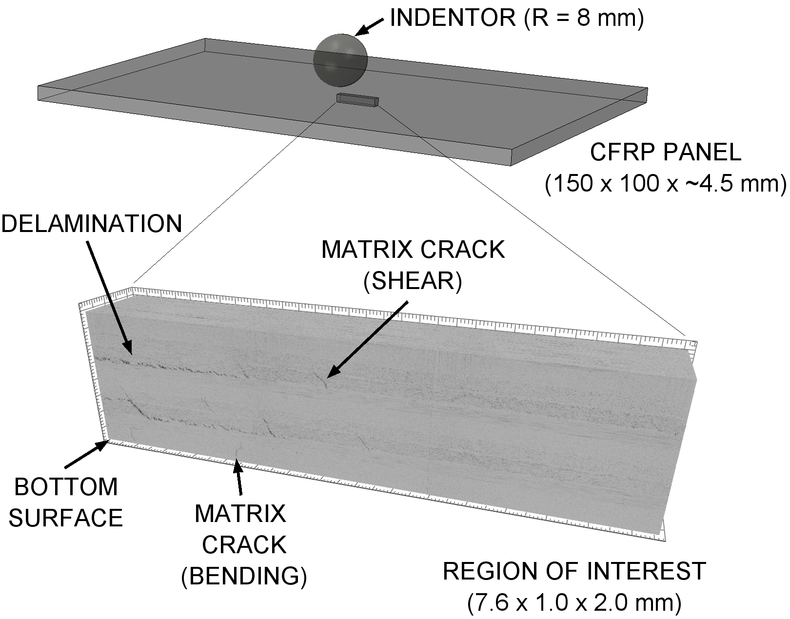
To induce the required damage for imaging, the samples were laid over a window, and subject to a through-thickness load, applied to the centre of the plates. A displacement of the indentor (radius ) was applied.
To confirm the presence and mechanisms of damage seen in the samples, synchrotron Radiation Computed Laminography (SRCL) was employed. In SRCL, the sample is rotated about an axis inclined to the X-ray beam, allowing for less artefacts when scanning plate-like samples than would be possible with computed tomography (CT) [29, 30]. The ID19 beamline of the European Synchrotron Radiation Facility (ESRF) was used, with an average photon energy of . Scans were taken using 2400 projection images with exposure time. The pixel size was in the sample plane, with a total field of view of . Four adjoining scans were performed on each material, giving reconstructed volumes of x x along the bottom surface of the specimen. These parameters were chosen due to their previous successful use [31].
Figure 1 shows the resulting volume for the delaminating material, with delamination between the plies clearly visible. A matrix crack within one of the plies can also be seen (as the damage mechanisms exhibited in the two materials manufactured is not mutually exclusive). The damage in these volumes was manually segmented.
Materials and Methodology Part II - Dark-Field Imaging
Dark-field radiography was performed at the ID19 beamline of the ESRF synchrontron. A diffuser, made by clamping together a stack 6 sheets of P180 grit silicon-carbide sandpaper, placed upstream of the sample was used to create the speckle pattern. The sample was from the Gadox scintillator, coupled to a PCO.edge SCMOS detector with a magnifying objective. This gave a pixel size of in the sample plane. A polychromatic beam with mean photon energy was produced by a wiggler set to a gap of , and filtered using of aluminium and of copper. These parameters lead to the size of the features in the speckle pattern produced by the sandpaper was on the order of several pixels on the detector. 6 sheets of sandpaper produced a more visible pattern than with a single sheet, while not attenuating the beam too heavily.
The beam profile meant that the usable field of view on the detector was 1930 370 pixels, or . The sample was stepped through the beam in a grid pattern, with 560 frames taken in total giving a field of view of 5688 6322 pixels, or . These frames overlapped so that the area of the sample was covered in at least 10 frames, as the information from multiple images can be incorporated to increase the signal to noise ratio [22]. Fifty exposures were taken at each sample position, and averaged to reduce noise. This lead to to a total exposure time of for the 560 images taken of the sample. A reference image of the sandpaper without the sample present is also required, which again was the average of 50 exposures. Reference patterns were taken after every move of the sample in case stability was an issue, however this was not the case.
The dark-field images were extracted using the UMPA algorithm [18, 21] This algorithm works by comparing a reference image of just the speckle pattern (sandpaper alone in the beam) to the sample frames (sandpaper and sample in the beam). At every pixel in the image, the transformation of a window (with size 7 7 pixels in our case) between the sample and reference frames is calculated. The dark-field image is found by looking at how the speckle pattern has been blurred, and the transmission by the loss of intensity within the window.
Results and Discussion
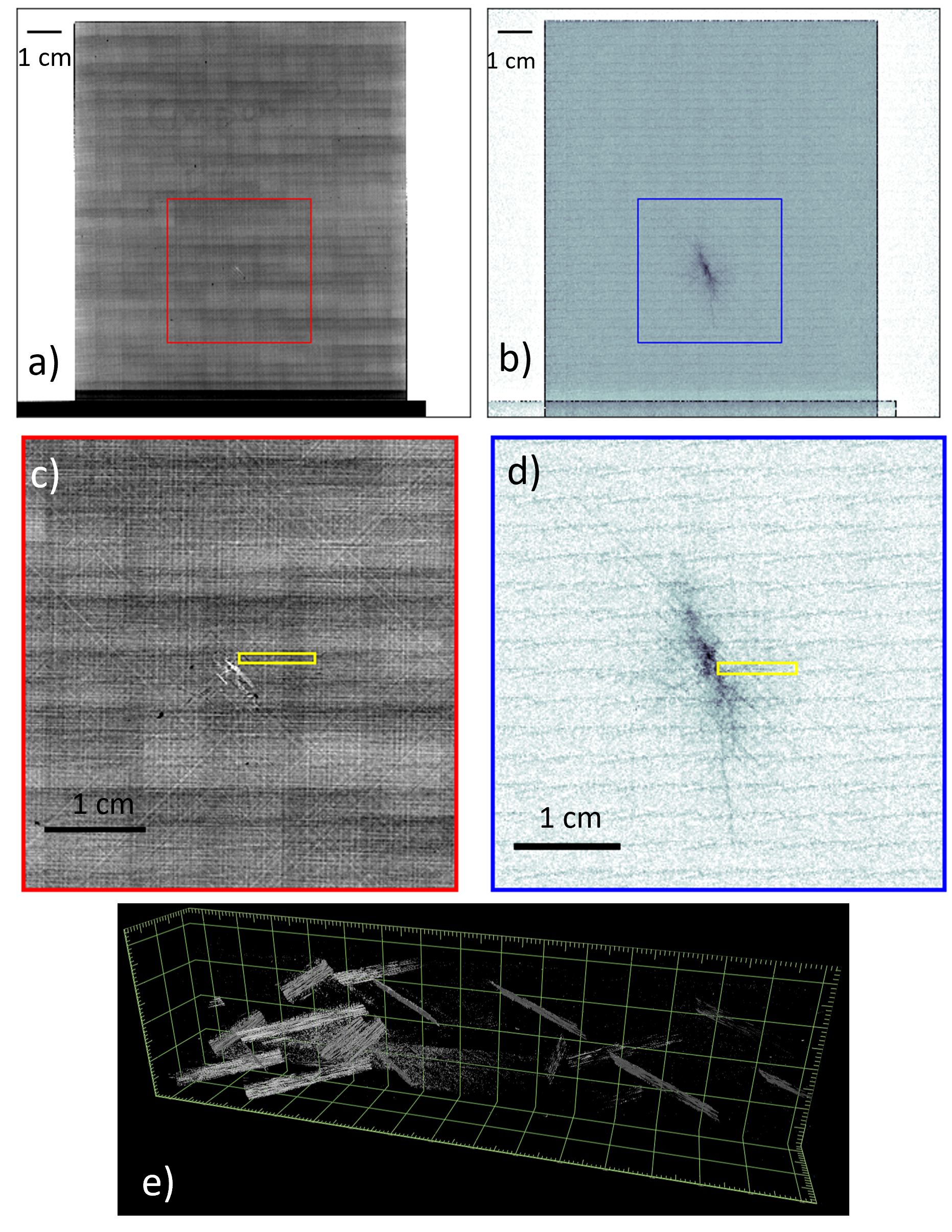
The results of the dark-field and CL imaging for the matrix-cracking material are shown in figure 2. Dark-field imaging produces a transmission as well as a dark-field image. This transmission image measures transmission in the sample, and is akin to what the imaging system would have produced if it was operating as a normal X-ray radiography setup. In the overview scan (Fig 2a and Fig 2b), the contrast in the transmission image has been set to differentiate the CFRP from the aluminium holder and the air. The faint horizontal and vertical lines in the transmission and dark-field images are due to fluctuations of the X-ray beam intensity in the individual frames that were taken to create the images shown. The position of the beam was also fluctuating slightly on the detector, making any correction for this impractically challenging. Regions of interest around the damage are shown in figures 2 c) and 2 d), in these the contrast has been further increased. This makes the damage in the transmission image just visible, and also improves the damage visibility in the dark-field image. The increased contrast in the dark-field images makes the crack running from the bottom of the impact site much clearer.
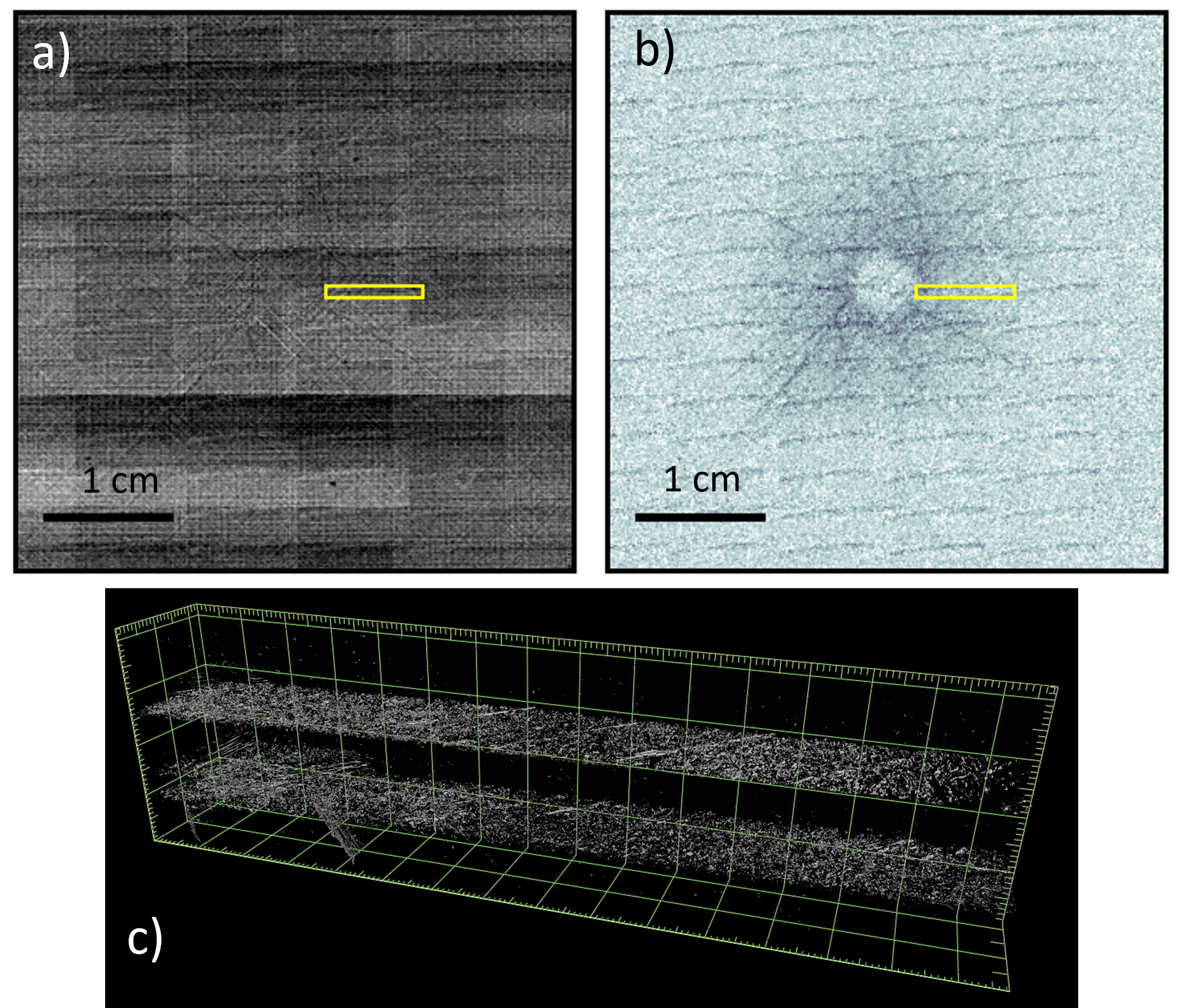
For the delaminating material (figs 3 a) and 3 b), we could not find a contrast level which made the damage visible in the transmission image. However, it is clear in dark-field. The difference between the dark-field images produced by the two materials is striking. For the delaminating material, the region directly under the impact site appears undamaged, with a halo of damage surrounding this region. A few cracks appear to be emanating from this halo. The matrix-cracking material has developed a large crack centred under the indentation site, again with several cracks propagating away from it.
The yellow boxes shown in the figures indicate the approximate regions in which the segmented CL volumes show in in figs 2 e) and 3 c) were taken. The segmented volume shows that following the out-of-plane loading, the matrix cracking material (fig 2 e) was more effective at suppressing delaminations, which have been shown to propagate under Mode-II dominated loading conditions and is consistent with the mateials higher Giic. Figure 3 c) shows that segmented damage in the delamination material was mainly localised along two planes between the plies of the laminate, corresponding to delaminations. One matrix crack is visible in the left hand side of the lower delamination layer in the volume. This may correspond to one of the cracks visible in the dark-field image (fig 3 d). The matrix-cracking material has many more matrix cracks (fig 2 e), caused by an increased toughness supressing delamination. Spatially, these are at a much higher density on the left-hand side of the volume, closer to the impact site, with a few smaller regions of damage further from the site. Due to the very strong dark-field signal given off at the very centre of the damaged region, the displayed contrast level used in the dark-field image for materials B (fig 2 d) makes seeing the effect of the few smaller matrix cracks at the right hand side of the segmented volume challenging. This shows that speckle-based dark-field imaging (as well as other dark-field techniques) are capable of detecting damage caused by both matrix cracking and delamination in BVID.
Our use of speckle-based imaging shows that dark-field visualisation of BVID is possible without the use of customised optical elements employed in other dark-field imaging techniques. This technique is easily implementable at synchrotron imaging facilities worldwide, requiring no complex alignment procedures and only a sheet of sandpaper. Additionally, speckle-based dark-field imaging using the UMPA algorithm has been demonstrated compatible with laboratory sources as well [23, 24], potentially allowing for this technique to be integrated into lab-based non-destructive testing systems in future. The use of a polychromatic beam in this experiment highlights that a monochromatic beam is not required, however it is worth noting that a typical lab source would give a much broader spectrum of energies than the beam we used in the present work. The use of the UMPA technique of speckle-based imaging and its capabilities to stitch together frames with the sample in multiple positions to create a single image means the size of sample is limited only by the range of travel on the motors used to position the sample. As with CT [32], an optimisation of parameters could yield better results for imaging CFRP samples. Work towards dark-field imaging without optical elements at synchrotron sources is ongoing [33, 34]. Recently a single-shot technique exploiting monochromater energy harmonics alongside an energy-discriminating detector has been demonstrated [35], potentially allowing for optics-free dark-field X-ray imaging to be used for BVID detection in future.
Conclusion
We have successfully shown the dark-field radiography can effectively visualise barely visible impact damage. By imaging samples susceptible to matrix cracking and delamination, and verifying that these are the main damage mechanisms in each sample, we have show that dark-field radiography is sensitive to both damage mechanisms.
This was the first demonstration of visualising barely visible impact damage in dark-field using a speckle-based imaging techniques, showing that it is possible without the need for customised X-ray optical elements used in previous dark-field imaging demonstrations.
Acknowledgements
We acknowledge the European Synchrotron Radiation Facility (ESRF) for provision of synchrotron radiation facilities and we would like to thank Ludovic Brochs and Lukas Helfen for assistance and support in using beamline ID19. We thank Solvay for providing the samples.
We acknowledge funding from the European Research Councils Horizon 2020 Consolidator Grant project ’Scattering-based X-ray Imaging and Tomography’.
Data Availability
References
-
[1]
M. O. Richardson, M. J. Wisheart, Review of low-velocity impact properties of composite materials, Composites Part A: Applied Science and Manufacturing 27 (12 PART A) (1996) 1123–1131.
doi:10.1016/1359-835X(96)00074-7.
URL http://dx.doi.org/10.1016/1359-835X(96)00074-7 - [2] A. Wronkowicz-Katunin, A. Katunin, K. Dragan, Reconstruction of barely visible impact damage in composite structures based on non-destructive evaluation results, Sensors (Switzerland) 19 (21) (2019). doi:10.3390/s19214629.
-
[3]
A. Wronkowicz, K. Dragan, K. Lis, Assessment of uncertainty in damage evaluation by ultrasonic testing of composite structures, Composite Structures 203 (June) (2018) 71–84.
doi:10.1016/j.compstruct.2018.06.109.
URL https://doi.org/10.1016/j.compstruct.2018.06.109 -
[4]
S. C. Garcea, Y. Wang, P. J. Withers, X-ray computed tomography of polymer composites (2018).
doi:10.1016/j.compscitech.2017.10.023.
URL https://doi.org/10.1016/j.compscitech.2017.10.023 - [5] S. M. Spearing, P. W. Beaumont, Fatigue damage mechanics of composite materials. I: Experimental measurement of damage and post-fatigue properties, Composites Science and Technology 44 (2) (1992) 159–168. doi:10.1016/0266-3538(92)90109-G.
- [6] B. Yu, R. S. Bradley, C. Soutis, P. J. Withers, A comparison of different approaches for imaging cracks in composites by X-ray microtomography, Philosophical Transactions of the Royal Society A: Mathematical, Physical and Engineering Sciences 374 (2071) (2016). doi:10.1098/rsta.2016.0037.
-
[7]
L. Helfen, A. Myagotin, A. Rack, P. Pernot, P. Mikulík, M. Di Michiel, T. Baumbach, Synchrotron-radiation computed laminography for high-resolution three-dimensional imaging of flat devices, Physica Status Solidi (A) Applications and Materials Science 204 (8) (2007) 2760–2765.
doi:10.1002/pssa.200775676.
URL https://onlinelibrary.wiley.com/doi/10.1002/pssa.200775676 -
[8]
A. J. Moffat, P. Wright, L. Helfen, T. Baumbach, G. Johnson, S. M. Spearing, I. Sinclair, In situ synchrotron computed laminography of damage in carbon fibre-epoxy [90/0]s laminates, Scripta Materialia 62 (2) (2010) 97–100.
doi:10.1016/j.scriptamat.2009.09.027.
URL http://dx.doi.org/10.1016/j.scriptamat.2009.09.027 - [9] P. Cloetens, M. Pateyron-Salomé, J. Y. Buffière, G. Peix, J. Baruchel, F. Peyrin, M. Schlenker, Observation of microstructure and damage in materials by phase sensitive radiography and tomography, Journal of Applied Physics 81 (9) (1997) 5878–5886. doi:10.1063/1.364374.
-
[10]
D. Shoukroun, L. Massimi, M. Endrizzi, D. Bate, P. Fromme, A. Olivo, Edge illumination X-ray phase contrast imaging for impact damage detection in CFRP, Materials Today Communications 31 (February) (2022) 103279.
doi:10.1016/j.mtcomm.2022.103279.
URL https://doi.org/10.1016/j.mtcomm.2022.103279 - [11] M. Endrizzi, B. I. S. Murat, P. Fromme, A. Olivo, Edge-illumination X-ray dark-field imaging for visualising defects in composite structures, Composite Structures (2015). doi:10.1016/j.compstruct.2015.08.072.
-
[12]
S. Senck, M. Scheerer, V. Revol, B. Plank, C. Hannesschläger, C. Gusenbauer, J. Kastner, Microcrack characterization in loaded CFRP laminates using quantitative two- and three-dimensional X-ray dark-field imaging, Composites Part A: Applied Science and Manufacturing 115 (August) (2018) 206–214.
doi:10.1016/j.compositesa.2018.09.023.
URL https://doi.org/10.1016/j.compositesa.2018.09.023https://linkinghub.elsevier.com/retrieve/pii/S1359835X18303804 - [13] J. Rus, A. Gustschin, H. Mooshofer, J. C. Grager, K. Bente, M. Gaal, F. Pfeiffer, C. U. Grosse, Qualitative comparison of non-destructive methods for inspection of carbon fiber-reinforced polymer laminates, Journal of Composite Materials 54 (27) (2020) 4325–4337. doi:10.1177/0021998320931162.
- [14] F. Pfeiffer, M. Bech, O. Bunk, P. Kraft, E. F. Eikenberry, C. Brönnimann, C. Grünzweig, C. David, Hard-X-ray dark-field imaging using a grating interferometer, Nature Materials 7 (2) (2008) 134–137. doi:10.1038/nmat2096.
- [15] J. Glinz, J. Šleichrt, D. Kytýř, S. Ayalur-Karunakaran, S. Zabler, J. Kastner, S. Senck, Phase-contrast and dark-field imaging for the inspection of resin-rich areas and fiber orientation in non-crimp vacuum infusion carbon-fiber-reinforced polymers, Journal of Materials Science 56 (16) (2021) 9712–9727. doi:10.1007/s10853-021-05907-0.
- [16] D. Shoukroun, L. Massimi, M. Endrizzi, A. Nesbitt, D. Bate, P. Fromme, A. Olivo, Quantification of porosity in composite plates using planar x-ray phase contrast imaging, NDT and E International 139 (10 2023). doi:10.1016/j.ndteint.2023.102935.
- [17] Özgul Öztürk, R. Brönnimann, P. Modregger, Defect detection in glass fabric reinforced thermoplastics by laboratory-based x-ray scattering, Composites Part B: Engineering 252 (3 2023). doi:10.1016/j.compositesb.2023.110502.
-
[18]
M.-C. Zdora, State of the Art of X-ray Speckle-Based Phase-Contrast and Dark-Field Imaging, Journal of Imaging 4 (5) (2018) 60.
doi:10.3390/jimaging4050060.
URL http://www.mdpi.com/2313-433X/4/5/60 - [19] M.-C. Zdora, P. Thibault, W. Kuo, V. Fernandez, H. Deyhle, J. Vila-Comamala, M. P. Olbinado, A. Rack, P. M. Lackie, O. L. Katsamenis, M. J. Lawson, V. Kurtcuoglu, C. Rau, F. Pfeiffer, I. Zanette, X-ray phase tomography with near-field speckles for three-dimensional virtual histology, Optica 7 (9) (2020) 1221. doi:10.1364/optica.399421.
- [20] M. C. Zdora, P. Thibault, T. Zhou, F. J. Koch, J. Romell, S. Sala, A. Last, C. Rau, I. Zanette, X-ray Phase-Contrast Imaging and Metrology through Unified Modulated Pattern Analysis, Physical Review Letters 118 (20) (2017) 1–6. doi:10.1103/PhysRevLett.118.203903.
-
[21]
F. De Marco, S. Savatović, R. Smith, V. Di Trapani, M. Margini, G. Lautizi, P. Thibault, High-speed processing of X-ray wavefront marking data with the Unified Modulated Pattern Analysis (UMPA) model, Optics Express 31 (1) (2023) 635.
doi:10.1364/OE.474794.
URL https://opg.optica.org/abstract.cfm?URI=oe-31-1-635 -
[22]
R. Smith, F. De Marco, L. Broche, M.-C. Zdora, N. W. Phillips, R. Boardman, P. Thibault, X-ray directional dark-field imaging using Unified Modulated Pattern Analysis, PLOS ONE 17 (8) (2022) 1–12.
doi:10.1371/journal.pone.0273315.
URL https://doi.org/10.1371/journal.pone.0273315 - [23] M.-C. Zdora, I. Zanette, T. Walker, N. Phillips, R. Smith, H. Deyhle, S. Ahmed, P. Thibault, X-ray phase imaging with the unified modulatedpattern analysis of near-field speckles at alaboratory source, Applied Optics 59 (8) (2020) 2270–2275. doi:10.1364/ao.384531.
-
[24]
R. Smith, R. Boardman, P. Thibault, Speckle-based directional dark-field x-ray imaging with a liquid-metal-jet source, AIP Conference Proceedings (2023) 040014doi:10.1063/5.0168156.
URL http://aip.scitation.org/doi/abs/10.1063/5.0168156 - [25] R. Smith, K. Morgan, A. McCarron, P. Cmielewski, N. Reyne, D. Parsons, M. Donnelley, Ultra-fastin vivodirectional dark-field x-ray imaging for visualising magnetic control of particles for airway gene delivery, Phys. Med. Biol. 69 (10) (2024) 105025. doi:10.1088/1361-6560/ad40f5.
-
[26]
C. Bouvet, S. Rivallant, J. Barrau, Low velocity impact modeling in composite laminates capturing permanent indentation, Composites Science and Technology 72 (16) (2012) 1977–1988.
doi:10.1016/j.compscitech.2012.08.019.
URL http://dx.doi.org/10.1016/j.compscitech.2012.08.019https://linkinghub.elsevier.com/retrieve/pii/S0266353812003223 -
[27]
D. J. Bull, A. E. Scott, S. M. Spearing, I. Sinclair, The influence of toughening-particles in CFRPs on low velocity impact damage resistance performance, Composites Part A: Applied Science and Manufacturing 58 (2014) 47–55.
doi:10.1016/j.compositesa.2013.11.014.
URL http://dx.doi.org/10.1016/j.compositesa.2013.11.014 - [28] Astm standard tests., https://www.astm.org/ (2023).
- [29] L. Helfen, A. Myagotin, A. Rack, P. Pernot, P. Mikulík, M. D. Michiel, T. Baumbach, Synchrotron-radiation computed laminography for high-resolution three-dimensional imaging of flat devices, Physica Status Solidi (A) Applications and Materials Science 204 (2007) 2760–2765. doi:10.1002/pssa.200775676.
- [30] L. Helfen, A. Myagotin, P. Mikulk, P. Pernot, A. Voropaev, M. Elyyan, M. D. Michiel, J. Baruchel, T. Baumbach, On the implementation of computed laminography using synchrotron radiation, Review of Scientific Instruments 82 (6 2011). doi:10.1063/1.3596566.
- [31] G. Borstnar, M. N. Mavrogordato, L. Helfen, I. Sinclair, S. M. Spearing, Interlaminar fracture micro-mechanisms in toughened carbon fibre reinforced plastics investigated via synchrotron radiation computed tomography and laminography, Composites Part A: Applied Science and Manufacturing 71 (2015) 176–183. doi:10.1016/j.compositesa.2015.01.012.
-
[32]
P. Galvez-Hernandez, R. Smith, K. Gaska, M. Mavrogordato, I. Sinclair, J. Kratz, The effect of x-ray computed tomography scan parameters on porosity assessment of carbon fibre reinfored plastics laminates, Journal of Composite Materials 57 (29) (2023) 4535–4548.
doi:10.1177/00219983231209383.
URL http://dx.doi.org/10.1177/00219983231209383 - [33] T. A. Leatham, D. M. Paganin, K. S. Morgan, X-ray dark-field and phase retrieval without optics, via the fokker–planck equation, IEEE Transactions on Medical Imaging 42 (6) (2023) 1681–1695. doi:10.1109/TMI.2023.3234901.
-
[34]
J. N. Ahlers, K. M. Pavlov, M. J. Kitchen, K. S. Morgan, X-ray dark-field via spectral propagation-based imaging, Optica 11 (8) (2024) 1182–1191.
doi:10.1364/OPTICA.506742.
URL https://opg.optica.org/optica/abstract.cfm?URI=optica-11-8-1182 -
[35]
J. N. Ahlers, K. M. Pavlov, M. J. Kitchen, S. A. Harker, E. J. Pryor, J. A. Pollock, M. K. Croughan, Y. Y. How, M.-C. Zdora, L. F. Costello, D. W. O’Connell, C. Hall, K. S. Morgan, Single-exposure x-ray dark-field imaging via a dual-energy propagation-based setup, Opt. Lett. 50 (7) (2025) 2171–2174.
doi:10.1364/OL.553310.
URL https://opg.optica.org/ol/abstract.cfm?URI=ol-50-7-2171 -
[36]
R. Smith, V. Di Trapani, G. Lautizi, F. De Marco, S. Savatovis, P. Thibault, Speckle-based directional dark-field tomography on carbon fibre composites [dataset]. european synchrotron radiation facility (2022).
doi:10.15151/ESRF-ES-779305051.
URL https://doi.org/10.15151/ESRF-ES-779305051 -
[37]
F. De Marco, P. Thibault, R. Smith, S. Savatovic, optimato/umpa: Initial release of c++ version (Aug. 2022).
doi:10.5281/zenodo.6984740.
URL https://doi.org/10.5281/zenodo.6984740