Satellite Federated Fine-Tuning for Foundation Models in Space Computing Power Networks
Abstract
Advancements in artificial intelligence (AI) and low-earth orbit (LEO) satellites have promoted the application of large remote sensing foundation models for various downstream tasks. However, direct downloading of these models for fine-tuning on the ground is impeded by privacy concerns and limited bandwidth. Satellite federated learning (FL) offers a solution by enabling model fine-tuning directly on-board satellites and aggregating model updates without data downloading. Nevertheless, for large foundation models, the computational capacity of satellites is insufficient to support effective on-board fine-tuning in traditional satellite FL frameworks. To address these challenges, we propose a satellite-ground collaborative federated fine-tuning framework. The key of the framework lies in how to reasonably decompose and allocate model components to alleviate insufficient on-board computation capabilities. During fine-tuning, satellites exchange intermediate results with ground stations or other satellites for forward propagation and back propagation, which brings communication challenges due to the special communication topology of space transmission networks, such as intermittent satellite-ground communication, short duration of satellite-ground communication windows, and unstable inter-orbit inter-satellite links (ISLs). To reduce transmission delays, we further introduce tailored communication strategies that integrate both communication and computing resources. Specifically, we propose a parallel intra-orbit communication strategy, a topology-aware satellite-ground communication strategy, and a latency-minimalization inter-orbit communication strategy to reduce space communication costs. Simulation results demonstrate significant reductions in training time with improvements of approximately 33%.
Index Terms:
Satellite federated learning, fine-tuning, foundation models, edge learning, and satellite communications.
I Introduction
The proliferation of low-earth orbit (LEO) satellites, driven by advancements in satellite technology, has established them as indispensable tools for acquiring high-resolution imagery of the Earth’s surface. These data play a pivotal role in Earth observation applications such as environmental monitoring [1] and land cover classification [2]. Simultaneously, artificial intelligence (AI) has experienced remarkable growth over recent decades, substantially contributing to the development of remote sensing data interpretation. In the remote sensing field, the most commonly used backbone of the learning models can be categorized into convolutional neural networks (CNNs) and Transformers [3]. CNN-based models, with the unique architecture of convolutional layers, can automatically extract hierarchical and discriminative features and preserve spatial information from remote sensing images, such as scene classification [4]. Transformer-based models, such as variants of Vision Transformer, capture long-range dependency better than the CNN-based models [5]. Transformer-based models are applied in many scenarios in the remote sensing field, including generalist geospatial AI (e.g., Prithvi [6]), visual tasks (e.g., SatMAE [7] and SatMAE++ [8]), and spectral data analysis (e.g., SpectralGPT [9]). These foundation models are pre-trained on large-scale remote sensing datasets and fine-tuned on specific tasks to enhance their performance in various downstream tasks.
Traditional data-driven model training has limitations as it needs to download raw satellite data to terrestrial cloud servers. Firstly, satellite-ground communication faces short communication durations due to satellite movement, which poses a challenge to the real-time transmission of the original data. Secondly, the high resolution of remote sensing images has made the satellite-ground links (SGL) with only a few hundred Mbps become the transmission bottleneck. For instance, transmitting a scene at 0.5-meter resolution over a 30-kilometer view width results in approximately 40 GB of data transfer between satellites and ground stations (GSs). Finally, the direct transmission of original data exposes sensitive information, leading to serious privacy and security issues. At the same time, the communication and on-orbit computing technologies of satellite networks are becoming increasingly mature, which lays a foundation for the development of space computing power networks (Space-CPN). In Space-CPN, satellites are combined with terrestrial devices to form a network. By performing real-time data processing on-board, Space-CPN can detect and analyze real-time environmental changes, such as forest fires, floods, and climate change. However, fully leveraging the potential of Space-CPN requires an efficient approach to training AI models across distributed satellite nodes while minimizing communication overhead.
A promising solution to this challenge is satellite federated learning (SFL), which enables satellites to collaboratively train AI models without requiring raw data to be transmitted to ground stations [10, 11, 12]. While SFL has been explored in prior studies, most existing work focuses on small-scale models. Despite the rapid development of Space-CPN, onboard computation capabilities remain significantly constrained compared to terrestrial AI clusters, making the fine-tuning of large models a major challenge. Satellite federated learning, as a solution for distributed training, supports collaborative training among satellites [10, 11]. To solve this problem, it is a feasible solution to decompose and deploy the computing tasks of fine-tuning large models in Space-CPN and use the distributed computation capabilities for federated fine-tuning [13, 14]. According to the distribution of computation capabilities in Space-CPN, the modules are deployed as follows: the embedding layer is deployed on satellites because satellites are data sources, the backbone network is deployed on the terrestrial server, and the classification layer generating outputs is deployed on satellites, as illustrated in Fig. 1.
In this deployment framework, the primary challenge lies in the communication process. During forward propagation, satellites compute local embedding vectors and perform intra-orbit aggregation. Notably, while raw satellite data can reach gigabyte levels in total size, the transmitted embedding vectors for each sample are only a few megabytes, significantly alleviating communication overhead. Once computed, these embedding vectors are transmitted to the ground for feature vector computation. In this process, satellite-ground communication faces some special challenges compared with transmission on the ground [14]. Firstly, due to the movement of satellites, especially LEO satellites that circle the Earth at high speeds, SGLs are dynamic and unstable. Secondly, it takes much time to access the GS for each satellite. Besides, the insufficient bandwidth of SGLs leads to slower data rates and higher latency. Then, feature vectors are sent back to satellites for output generation, which faces similar questions as embedding vector downloading. Finally, satellites update local models and aggregate a global model through ISLs. The dynamic ISLs make link selection and allocation extremely complex in terms of network management.
To address the above-mentioned challenges, in this paper, we propose a satellite-ground collaborative federated fine-tuning framework, which decomposes the modules of remote sensing foundation model based on the distribution of computing power between space and ground networks. During the federated fine-tuning procedures, we address challenges during satellite-ground communication for embedding vector downloading and feature vector uploading, intra-orbit communication for embedding vector aggregation, and inter-orbit communication for global head aggregation. We design the corresponding collaborative transmission method combined with the process of computation tasks. The major contributions of this paper are summarized as follows:
-
1.
We propose an efficient satellite-ground collaborative federated fine-tuning framework that strategically decomposites the fine-tuning task for remote sensing foundation models by allocating the modules between GSs and satellites. This framework offers a practical solution for on-board remote sensing foundation model fine-tuning, ensuring data privacy and alleviating satellite-ground communication bottlenecks.
-
2.
We introduce customized communication strategies for satellite-ground and inter-satellite transmission according to the inherent characteristics of transmission links (e.g., intermittent SGLs, stable intra-orbit ISLs, and time-varying inter-orbit ISLs). For sporadic satellite-ground communication, we propose a topology-aware communication strategy that allocates transmission tasks for SGLs according to real-time topology and link states. For intra-orbit communication, we propose a parallel communication strategy based on Ring Allreduce for the ring topology of each orbit. For inter-orbit communication, we propose a communication algorithm to minimize latency according to link capacity. These strategies integrate communication with computation processes, taking into account factors such as bandwidth limitations, sparse connection, and dynamic topology, optimize data transmission efficiency, and accelerate model convergence.
-
3.
We conduct extensive simulations to evaluate the performance of the proposed framework and communication strategies. The simulation results demonstrate that the proposed framework, coupled with the optimized communication strategies, significantly mitigates training latency, reduces transmission overhead, and improves the convergence speed of the model.
The remainder of the paper is organized as follows. Section II introduces relevant research on satellite FL. Section III formulates satellite-ground collaborative federated learning, introduces communication networks, and outlines the module decomposition and deployment framework. The workflow of the proposed framework is described in Section IV. In Section V, communication algorithms are designed to optimize transmission procedures. Section VI presents simulation results, followed by the conclusion in Section VII.
II Related Works
II-A Centralized Satellite FL
In centralized satellite FL, a coordinator, such as a PS, collects model updates from satellites. Satellites perform local training on their datasets and then send the model updates to the central coordinator. Some algorithms employ only SGLs during training, where models are trained on-board and transmitted via SGLs for global model aggregation at the PS. These algorithms are usually designed to address the challenges of time-varying and unstable SGLs. For instance, the algorithm proposed in [15] adjusted aggregation intervals based on the density of satellite-ground connections to increase the frequency of model updates. [16] proposed an over-the-air computation based scheme and optimized both uplink and downlink communications through beamforming. Considering the variations in connection time and connection density among satellites, asynchronous FL is introduced to mitigate the effects of stragglers, allowing satellites to send model updates to the server asynchronously [17, 18]. A compensation mechanism proposed in [19] addressed gradient staleness by adjusting the updates according to discrepancies.
Satellite FL with SGLs presents significant drawbacks, such as high latency due to satellite-ground communication delays. So some work adopts ISLs to enable model aggregation among satellites, thereby reducing the data transmission via SGLs. Some studies use high-altitude platforms as the coordinator for improved communication efficiency and a more favorable communication environment, such as [20]. FedISL leverages stable intra-orbit ISLs for intra-orbit model aggregation, predicts satellite movement and sends intra-orbit aggregated models through SGLs for global model aggregation [21]. AsyncFLEO utilizes satellites as relays, employs asynchronous FL, and proposes a model propagation algorithm that incorporates satellite grouping and stale update discounts to accelerate convergence, improve model accuracy, and balance the idle time and model staleness [22].
II-B Decentralized Satellite FL
To eliminate the reliance on the central coordinator, decentralized satellite FL is proposed, where satellites exchange model parameters directly with other satellites through ISLs. In this context, the primary focus is on designing inter-orbit transmission schemes aimed at minimizing transmission time or energy consumption. The scheme in [23] aggregates a global model at each training round and strives to minimize energy consumption. Some decentralized Satellite FL incorporates the gossip learning, where satellites communicate with their neighbors for partial model aggregation at each training round [24, 25, 26]. [25] offloads data through ISLs to balance data distribution and optimize delay and accuracy within computation and communication power constraints. DFedSat in [26] reduces communication costs and improves system robustness by implementing a self-compensation mechanism to address packet loss. [27] proposed a number control scheme to minimize the convergence time of decentralized satellite FL through optimization of constellation configurations.
Numerous efforts have been made to accelerate the convergence of satellite FL by addressing communication challenges such as intermittent satellite-ground communication and dynamic inter-satellite communication. However, most existing works rely on satellites to train models and ignore the challenges of on-board large model training stemming from insufficient computation capacity. To overcome these limitations, we propose a satellite-ground collaborative federated fine-tuning framework to train large models.
III System model
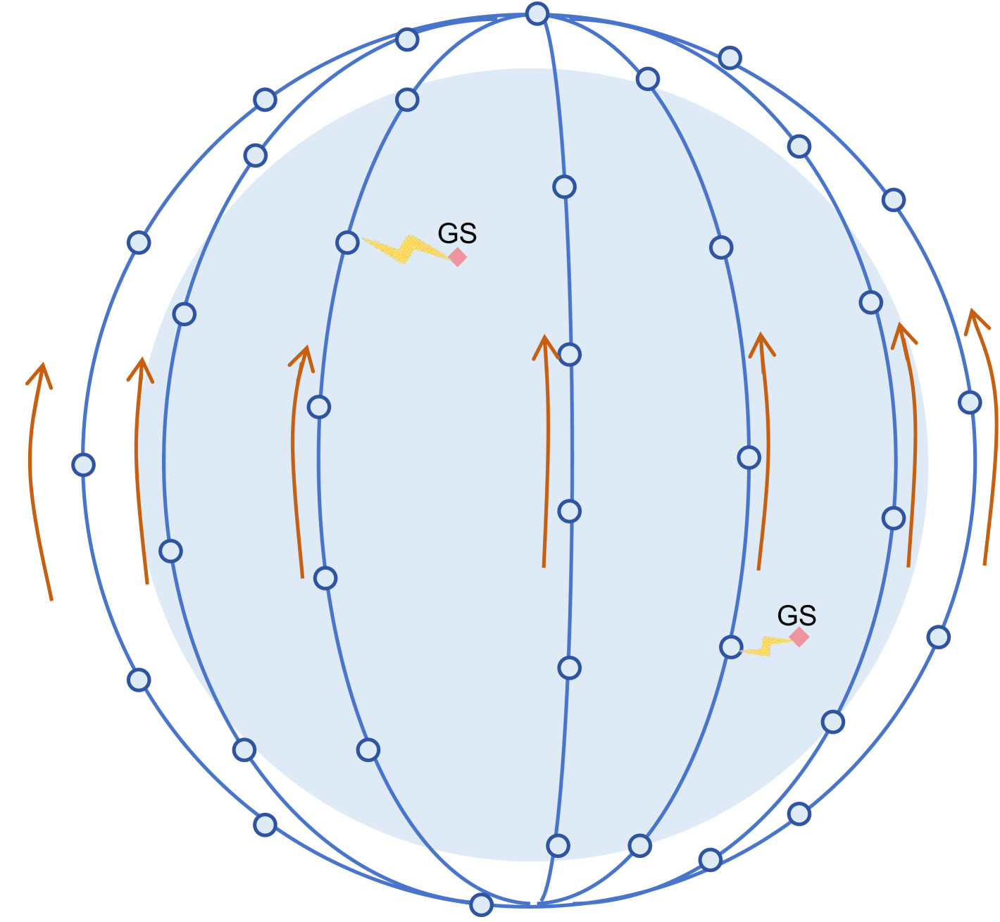
Consider a general Walker constellation, which has remarkable advantages in global coverage and is widely utilized in various communication and LEO systems like Starlink, OneWeb, and Kuiper [28]. The Walker constellation is formulated by the parameters , where is the inclination, is the total number of satellites, is the number of orbit planes, is the phase factor of two adjacent orbits, and is the altitude of orbits. In the LEO satellite constellation, satellites orbit the Earth at an altitude ranging approximately from 500 to 1500 kilometers. Orbit planes and satellites are evenly spaced as depicted in Fig. 2. Each orbit encompasses satellites, and the satellites are indexed by the set , where denotes the -th satellite in the -th orbit.
III-A Satellite Federated Fine-Tuning
In Space-CPN, each satellite stores massive remote sensing data within a Walker constellation, which can be harnessed to train AI models with federated fine-tuning for downstream remote sensing tasks, including environmental monitoring and land cover classification. A satellite FL system comprises a ground PS responsible for coordination and global model aggregation, alongside multiple GSs tasked with facilitating data transmission between satellites and the PS. Each satellite trains its local model on the local dataset without transmitting the raw dataset to the GSs. The goal of satellite FL is to collaboratively train a global model to minimize the global loss, which is mathematically expressed as:
| (1) |
where represents the local dataset on satellite , is the size of the local dataset, is the total number of data samples, and the function denotes the local loss function dependent on the local dataset and the local model . Conventional satellite FL adheres to the subsequent steps:
III-A1 Initialization
The ground PS transmits the initialized model to all satellites, and each satellite initializes its local model by
| (2) |
III-A2 Local Update
At the training round , each satellite updates its local model through the stochastic gradient descent (SGD) algorithm, which is given by
| (3) |
where represents the learning rate and denotes the stochastic gradient oracle.
III-A3 Global aggregation
The local models from different satellites are first transmitted to GSs and subsequently relayed to the ground PS for global aggregation [29]. The global aggregation formula is
| (4) |
III-B Communication Networks
In Space-CPN, communication serves as the fundamental enabler for data exchange, resource coordination, and overall system operation. Without communication, the individual computing nodes in space would be isolated, so we analyze the characteristics of communication networks.
III-B1 Ground Communication Network
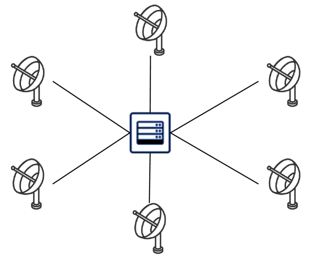
During federated fine-tuning, training information is exchanged between satellites and GSs for global aggregation. As depicted in Fig. 2, there are GSs and a PS situated on the ground, and all GSs are connected with the PS. The PS serves as the central coordinator in this system, while the GSs act as relays that facilitate communication between the satellites and the PS. The communication links between the GSs and the PS are fixed and characterized by high-speed fabric connectivity, ensuring stable and fast transmission [30]. To represent the characteristics of the ground communication network, we model it as a stable star network, as illustrated in Fig. 3(b), where the PS is the central node and transmission between the central node and other nodes is fast.
III-B2 Satellites Communication Network
LEO satellites are capable of communicating with each other through laser ISLs. There exist two distinct types of laser ISLs: intra-orbit ISLs for communication between two adjacent satellites within the same orbit, and inter-orbit ISLs for communication between two satellites in adjacent orbits. Each satellite typically establishes four ISLs: two intra-orbit ISLs established with and and two inter-orbit ISLs with and . Laser ISLs are widely utilized as primary inter-satellite communication links by many constellations such as Kuiper, Telesat, and Starlink [31]. The power received is expressed by
| (5) |
where is the transmitting power, and are the receiving and transmitting efficiencies, is the pointing loss, and is the path loss [32]. The pointing loss due to misalignment from satellite jitter and tracking noise can be expressed as
| (6) |
where and are the pointing error angles. The free-space path loss is calculated as
| (7) |
where is the wavelength and is the distance. The noise is the additive white Gaussian noise with variance , so the achievable data rate of laser ISLs is given by
| (8) |
where is the bandwidth and is the signal-to-noise ratio [33]. Laser ISLs have high data rates and can provide a transmission speed of 100 Gbps [34]. The satellite communication network composed of ISLs has the following characteristics:
-
•
Stable intra-orbit communication. The intra-orbit ISLs between adjacent satellites ensure stable and consistent connectivity, as these adjacent satellites within the same orbit possess identical velocities and are situated at relatively short distances from one another. All satellites within the same orbit are interconnected end to end, forming a stable ring structure.
-
•
Unstable inter-orbit communication. Some satellites in adjacent orbits move in opposite directions in the Walker constellation, as depicted in Fig. 2. Inter-orbit ISLs between these satellites, known as cross-seam inter-orbit ISLs, face challenges such as the Doppler shift and limited communication windows due to the rapid movement of satellites [35]. Consequently, cross-seam ISLs are generally not utilized for inter-satellite communication because of their instability.
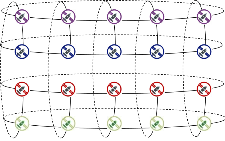
Leveraging these characteristics, satellites within the same orbit can be modeled as a ring topology. The LEO constellation comprises a collection of such rings, with adjacent rings interconnected by inter-orbit ISLs, excluding cross-seam ISLs, as depicted in Fig. 3(a).
III-B3 Satellite-Ground Communication Network
Satellite-ground communication is essential for cooperation during fine-tuning. Satellite-ground channels can be modeled as frequency selective channels with path loss and attenuation [36]. The definition of free-space path loss remains consistent with Equation 7. The attenuation due to rain is presented as
| (9) |
where and are the rain attenuation coefficients, is the rain rate, and is the path length in the rain area [37]. The received power for each path is expressed as
| (10) |
where is the transmit power of SGLs, is the wavelength of satellite-ground signals, is the reflection coefficient, and is the phase difference respect to the direct path. The total multipath received power for paths is derived as
| (11) |
The total received power is then:
| (12) |
SGLs can provide transmission speeds on the order of Mbps, which is insufficient for satellite data transmission. Due to the movement of satellites, the satellite-ground topology exhibits the following characteristics:
-
•
Intermittent connectivity. A satellite becomes visible to a ground station (GS) when it orbits overhead. The period during which the satellite is visible to a GS is termed the communication window. Since satellites are not always within the visible range of GSs due to their movement, it may take hours to move from one visible range to another. Consequently, SGLs experience intermittent connectivity, resulting in sparse satellite-ground links.
-
•
Short communication window. Satellites only communicate with the GS when it is in the visible range. However, due to their rapid movement, LEO satellites quickly pass through this range, leading to short communication windows, typically lasting only a few minutes.
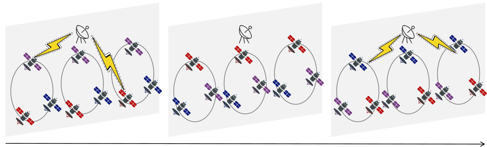
When analyzing SGLs, we sample some time points discretely over a period. A satellite and a GS can communicate between and if at least one link is feasible at . The interval between two adjacent time points is 1 minute. At different time points, the topology of SGLs varies. Thus, we model satellite-ground communication links as time-varying topology, as depicted in Fig. 3(c).
III-C Satellite Federated Fine-Tuning for Remote Sensing Foundation Models
Remote sensing foundation models (RS FMs) are specifically designed to analyze RS data from remote sensing devices, such as satellites and drones. These huge FMs are pre-trained and can be fine-tuned to enhance their accuracy and efficiency in specific downstream tasks. Typically, RS FMs consist of the embedding layer, backbone network, and task-specific head, as shown in Fig. 1. Take SpectralGPT as an example, the workflow is as follows [9]. First, images are split into patches and the embedding layer embeds image patches, adds position embeddings, and outputs embedding vectors. Then, the embedding vectors are fed into the backbone network to extract feature vectors. The computation load of the backbone network accounts for the vast majority of the total computation load of the model. Finally, for each downstream task, a learnable task-specific head is connected to the model. This head receives feature vectors as inputs and outputs results. During fine-tuning, only head parameters are updated, while other parameters remain fixed in each training round .
| (13) |
where represents the learning rate, and denotes the gradient of the loss function. Since only the head parameters are updated, only head parameters need to be aggregated:
| (14) |
The goal of federated fine-tuning is to find optimal head parameters, similar to satellite FL.
| (15) |
Our primary objective is to address the computing power constraints of fine-tuning FMs on satellites. To achieve this, we employ a computation task decomposition technique, effectively splitting the FM into distinct components and deploying them based on requirements. To protect data privacy, we deploy the embedding layer and the task-specific head on the satellites. The backbone network, which bears most of the computational workload (approximately 99%), is deployed on the ground. This significantly reduces the computational burden on the satellites, allowing them to handle only about of the overall computational tasks. During the forward propagation process, embedding vectors and feature vectors are exchanged between the satellites and the ground. Notably, the size of these vectors is approximately 20 MB for a sample, a reduction of about a thousand times compared to the raw satellite imagery. This drastic reduction in data size not only enhances communication efficiency but also alleviates bandwidth requirements, making the system more cost-effective and practical for deployment in space-constrained environments.
Based on the scheme of task decomposition, the fine-tuning process can be systematically divided into two distinct stages: feature extraction from satellites to the ground and model update from the ground to satellites.
III-C1 Feature Extraction
Satellites begin by processing their respective local data through the local embedding layer. The generated embedding vectors are then transmitted from the satellites to the PS located on the ground. The PS further extracts features from embedding vectors by transformer blocks. This ensures that only processed data is sent over the communication link, thereby conserving bandwidth and enhancing security. Overall, this phase focuses on transforming raw satellite imagery into actionable features, with data flowing from satellites to the ground.
III-C2 Model Update
The feature vectors extracted by the transformer blocks at the ground PS are sent back to the respective satellites. Upon receiving the feature vectors, each satellite processes these vectors and outputs results, computes local loss, and updates local task-specific heads for downstream tasks. Finally, all the updated task-specific head parameters from various satellites are aggregated through ISLs. In this phase, data flows from the ground back to the satellites, facilitating a closed-loop learning process.
Repeat these two stages until the model converges. By decomposing the fine-tuning process into feature extraction and model update stages, we effectively manage computational resources, ensure data privacy, and ensure efficient model synchronization across a distributed satellite network.
IV Satellite-Ground Collaborative Federated Fine-Tuning
This section provides an overview of the proposed framework, designed to address computational constraints in fine-tuning large foundation models on satellites through a task decomposition mechanism. Large FMs require substantial computational resources for fine-tuning, and the limitation in on-board computing power becomes particularly apparent when fine-tuning these models. To address these challenges, we propose a task decomposition mechanism to partition the model and allocate different parts of the model to satellites and the PS, respectively. The trainable task-specific head and frozen embedding layer are deployed on satellites, while the frozen backbone network is deployed on the ground. This mechanism significantly reduces the on-board computation load and optimizes the combination of transmission and computation process. We elaborate on the two stages briefly introduced in the section III-C. Each training round is divided into two phases, feature extraction, and model update, as illustrated in Fig. 4.
IV-A Feature Extraction
IV-A1 Intra-Orbit Embedding Vector Broadcast
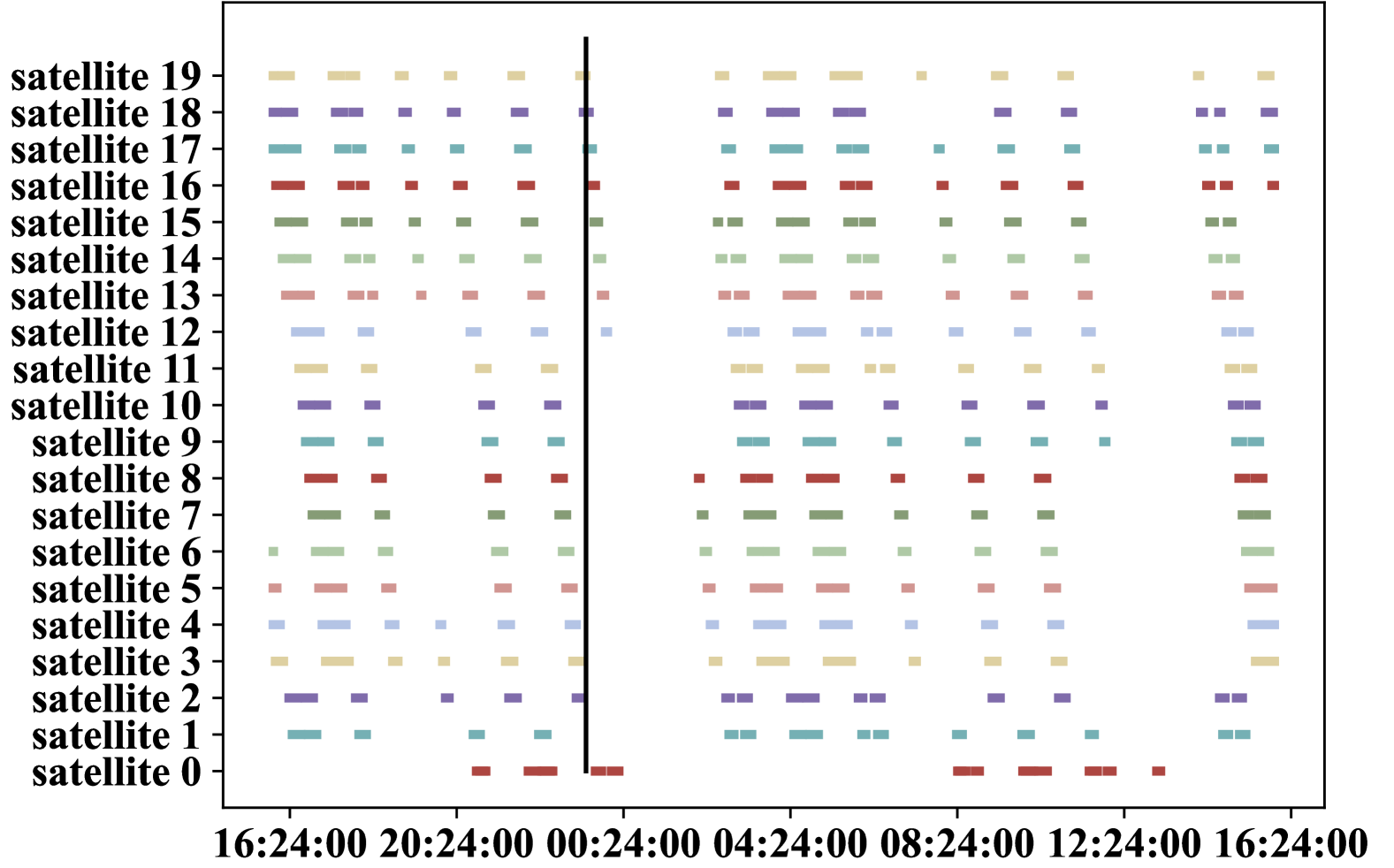
First, each satellite computes embedding vectors utilizing data stored locally. Then, all computed embedding vectors are broadcast within each orbit so that any satellite connected to a GS can transmit intra-orbit data to the ground for forward propagation. We visualize the connection windows between satellites and GSs throughout the day in Fig. 5 for comparison. Each connection window lasts for approximately minutes. If data transmission starts at 23:30, some satellites establish their first satellite-ground communication around three hours later. So the conventional method, where each satellite only sends its local embedding vectors without coordination, wastes the communication resources of other satellites. In contrast, our proposed method allows other intra-orbit satellites to transmit data immediately without waiting.
Due to the instability of inter-orbit ISLs and the volume of intra-orbit embedding vectors, embedding vectors are not exchanged between different orbits. To optimize this process, we have designed a parallel intra-orbit broadcast strategy, detailed in Section V-A, to make full use of each satellite’s communication capabilities. After the broadcast, each satellite stores the concatenated intra-orbit embedding vectors, represented as:
| (16) |
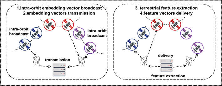
IV-A2 Embedding Vectors Transmission
Intra-orbit embedding vectors are transmitted from satellites to the PS in each orbit. A key challenge is that satellite-ground communication topology is time-varying, as illustrated in section III-B. To address this, we design a topology-aware satellite-ground transmission strategy in section V-B, which allows multiple orbits to independently utilize this strategy for parallel transmission. The algorithm takes into account the heterogeneity of different SGLs and allocates different transmission tasks to SGLs. Thus, the total transmission time is determined by the maximum transmission time across all orbits:
| (17) |
IV-A3 Terrestrial Feature Extraction
After receiving embedding vectors, the PS feeds them into the backbone network. The backbone network, consisting of dozens of transformer blocks, identifies the most relevant information from the input and outputs feature vectors:
| (18) |
Due to the high computational speed of the PS, the time cost of feature extraction is significantly reduced.
IV-A4 Feature Vectors Delivery
Finally, the feature vectors are delivered back to the satellites for the last step of forward propagation. The task-specific head receives these feature vectors and produces the output. This output serves as the basis for further processing in applications. For instance, in classification tasks, the model selects the class with the highest probability as its final prediction. This process also involves satellite-ground communication. Similar to the embedding vector transmission, we use a topology-aware communication strategy for parallel transmission from the PS to satellites in the orbit . Receivers then send the corresponding parts to other satellites in the same orbit.
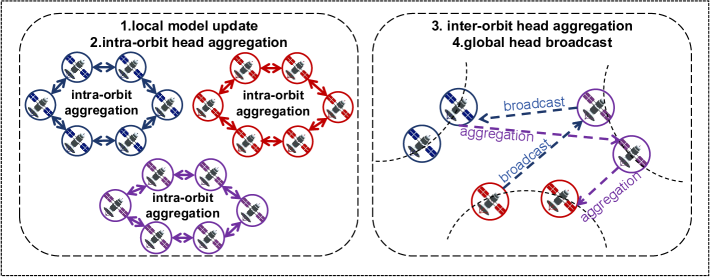
IV-B Model Update
IV-B1 Local Model Update
Subsequently, the output is utilized for back propagation in the model. The loss is computed to quantify the difference between the predicted output and the true labels. Once the loss is determined, back propagation is performed to calculate the gradients. These gradients are then used to update the model parameters, typically using an optimization algorithm such as stochastic gradient descent. After this step, the local fine-tuning process for a single satellite is completed.
IV-B2 Intra-orbit Head Aggregation
After local fine-tuning, the updated task-specific heads from all satellites within the same orbit are averaged to ensure model convergence in collaborative learning. Satellites exchange head parameters with each other in a decentralized way without a central terrestrial coordinator. Accounting for the intermittent nature of satellite-ground communication, we perform hierarchical aggregation through ISLs. Head parameters are first aggregated within each orbit
| (19) |
and then aggregated across different orbits. Due to the more stable communication conditions maintained by satellites within the same orbit, intra-orbit head aggregation employs a parallel communication strategy similar to that used in the embedding vector broadcast. This approach ensures efficient transmission.
IV-B3 Inter-orbit Head Aggregation
Intra-orbit heads from all orbits are aggregated to form a global head.
| (20) |
Head parameters are transmitted from orbit 1 to orbit through inter-orbit ISLs for global aggregation. To ensure efficient convergence and communication, the inter-orbit ISLs are carefully selected for transmission between two adjacent orbits. A path selection algorithm is proposed in section V-C, which can adapt to dynamic inter-orbit ISLs and automatically select the optimal path to minimize transmission latency.
IV-B4 Global Head Broadcast
Finally, the global model is transmitted back from orbit to orbit via inter-orbit ISLs. Within each orbit, the satellite receiving the global head then disseminates it to other satellites for the next round of training, where satellites continue to train using their local data. This step ensures that every satellite has access to the latest version of the global model. Notably, this can be efficiently achieved by simply reversing the direction of transmission during inter-orbit head aggregation.
In conclusion, each training round of the fine-tuning process comprises two primary phases: feature extraction and model update. These stages are repeated until the model converges. The entire fine-tuning procedure is delineated in Algorithm 1. During the training procedure, only the heads and embedding layers are computed on the satellites. By selectively computing only the most relevant or impactful parts of the model, this approach significantly reduces the computational load and offers a promising solution to address the computational challenges, particularly beneficial for resource-intensive model training.
V Space Communication Strategies
During fine-tuning, a substantial volume of crucial data, such as embedding vectors, feature vectors, and model parameters, is transmitted through ISLs and SGLs. Although the size of these data is significantly smaller than that of the original satellite data, data transmission still accounts for a considerable portion of the overall latency. To achieve efficient transmission, communication is optimized to address various challenges. For satellite-ground communication, SGLs are sporadic and intermittent, with short communication windows. Satellites usually need to wait for a long time to establish SGLs. For inter-satellite communication, links are dynamic. Therefore, in this section, we present the customized communication strategies for the satellite-ground, intra-orbit, and inter-orbit communication to accelerate convergence. The communication optimization is closely integrated with the computation process.
V-A Intra-Orbit Communication for Partial Head Aggregation
In certain stages, such as intra-orbit embedding vector broadcast and intra-orbit head aggregation, data is transmitted through intra-orbit ISLs. These processes can be abstracted into a unified communication model, where all communication clients establish a stable ring topology. Each client possesses local data that needs to be aggregated or concatenated with the data from other clients before being broadcast to all clients within the ring. If data is transmitted sequentially in each orbit, the transmission time increases as the number of satellites grows. In mega-constellations, the transmission delay can become significant.
To address this issue, we leverage the Ring Allreduce algorithm to accelerate intra-orbit communication. The Ring Allreduce algorithm is a distributed method designed to efficiently aggregate data across multiple clients in a ring topology. In essence, Allreduce means that each client contributes its data, and subsequently, every client receives the result of the reduction. The Ring Allreduce algorithm is particularly communication-efficient for achieving Allreduce in a ring topology. Inspired by the Ring Allreduce algorithm, we divide intra-orbit model transmission into two phases: a scatter-reduce phase and a gather phase.
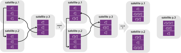
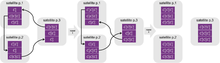
V-A1 Scatter-Reduce Phase
Each client splits its local data into equal-sized chunks, indexed by . During the communication round , each client exchanges its local chunk with its neighbors and , where . Each client sends a chunk to the next client in the ring and receives a chunk from the previous client. After rounds, each client holds the aggregation result of one chunk from all the clients, as illustrated in Fig. 6(a).
V-A2 Gather Phase
In this phase, each client sends the aggregated chunk to the next client and receives another aggregated chunk from its previous neighbor. After rounds, each aggregated chunk has traveled to all clients, allowing each client to have the complete data, as depicted in Fig. 6(b).
In the first and second phases of Ring Allreduce, each satellite receives data times, with each transmission involving bits of data, where denotes the total number of bits for size. Thus, the total time is given by:
| (21) |
Ring AllReduce has a constant communication complexity, meaning the communication cost is independent of the number of satellites, effectively mitigating the latency issue. Since each satellite sends and receives data simultaneously in each round, Ring AllReduce can make better use of parallelism and reduce idle time.
Based on the first phase of the ring all-reduce, we further optimize the intra-orbit orbit of embedding vectors, though they are not reduced but concatenated. In each round, all satellites transmit local vectors and receive vectors in a certain direction. Thus, the transmission time is reduced to:
| (22) |
It is evident that the time consumed by the Ring Allreduce-based transmission scheme is independent of the number of satellites. Therefore, the algorithm scales well with the number of satellites, making it highly suitable for large-scale constellations.
V-B Satellite-Ground Communication for Embedding Vector Transmission
SGLs are sparse, time-varying, and bandwidth-limited. Each satellite communicates with GSs several times daily, and communication windows are short. There is a long time interval between the establishment of SGLs for a satellite. These factors significantly influence the transmission time. We have devised the training steps where data is first broadcast within each orbit and then transmitted through SGLs to fully utilize each transmission opportunity and minimize idle time. However, we did not previously explain the strategy for satellite-ground communication. This section focuses on efficient satellite-ground transmission in each time slot. We have developed a topology-aware communication strategy aimed at maximizing data transmission within each communication window to reduce waiting time. To optimize the utilization of communication resources and shorten the transmission time, we adopt a multi-path parallel transmission scheme that leverages all feasible SGLs.
To effectively organize transmission tasks across heterogeneous SGLs, we model the satellite-ground communication network as a static flow network at each time point. This network is represented as a directed acyclic graph, wherein each edge possesses a capacity constraint, ensuring that the data flow does not exceed this limit. Data flow originates from the source vertex and is sent to the sink vertex. In this context, the source vertex represents the orbits, while the sink vertex corresponds to the PS. Data traverses from each orbit to the PS via intermediate satellites and GSs, which are depicted as vertices within the graph. The objective of satellite-ground transmission is to maximize the data flow through the network.
To achieve this objective, we first define the capacities of the edges. For any link , the capacity of its corresponding edge is , where denotes the total number of bits of data in orbit , denotes the data rate of link , and denotes the interval between two time points. Consequently, the capacity of each edge reflects the maximum proportion of data that can be transmitted over the corresponding link during this interval. Subsequently, we apply a max flow algorithm to this flow network to maximize the amount of data transferred from the source to the sink. Each satellite transmits the data according to the algorithm’s results until all data is transmitted to the PS. This approach fully leverages the satellite transmission opportunities and ensures the rapid transmission of data without exceeding the transmission capacity of the links.
V-C Inter-Orbit Communications for Global Head Aggregation
Satellite-ground communication suffers from intermittent SGLs, and the head aggregation does not necessitate the involvement of GSs. Therefore, we propose an aggregation scheme tailored for dynamic satellite networks, wherein satellites aggregate the global head via ISLs to avoid reliance on GSs and unreliable SGLs. The primary challenge for inter-orbit communication lies in the instability and time variability of inter-orbit ISLs. There are different aggregation algorithms designed according to the network topology of the clients, such as the fully connected topology, the ring topology, and so on. However, these designs prove ineffective in LEO satellite networks due to their neglect of satellite network characteristics: the stable ring topology of intra-orbit ISLs and the unstable topology of inter-orbit ISLs.
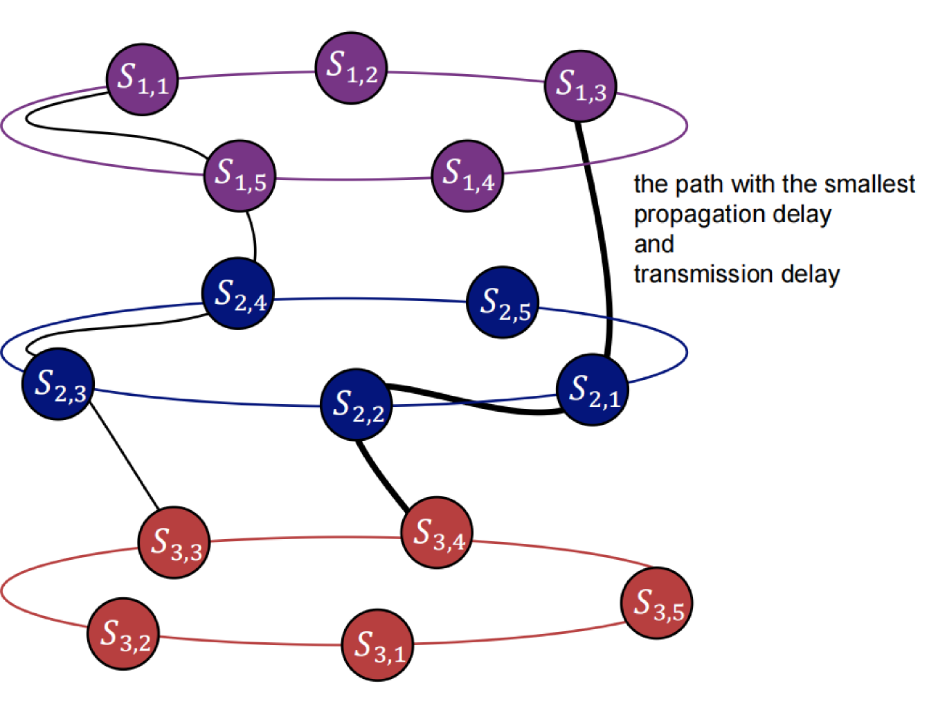
To propose an aggregation algorithm, it is imperative first to elucidate the network topology. We model the LEO satellite constellation as a network where vertices represent satellites and edges denote ISLs. Given the stability of the intra-orbit ISLs, satellites within the same orbit can be considered as a tightly connected cluster and hold the same data because intra-orbit aggregation is done before inter-orbit aggregation. We enumerate the clusters from to . There are a few links between cluster and cluster , . Cross-seam ISLs are not considered in the system, so there are no links between cluster and cluster . Our goal is to select a path covering all orbits to achieve fast and stable transmission from cluster to cluster . The definition of path is the trajectory along which data is transmitted from to through certain relay satellites. For example, signifies the path from satellite to satellite and can be expressed as , where is i-th relay satellite, is data source and is the destination. denotes the path from any satellite in orbit to any satellite in orbit . To complete global aggregation, the selected path must satisfy:
| (23) |
where computes the set of covered orbits in path . This constraint guarantees that the path can interconnect all orbits. The global model broadcast can be easily implemented by reversing the direction of transmission in the algorithm.
To accelerate transmission, path selection is crucial. The delay of data transmission comprises two types: transmission delay and propagation delay. Propagation delay is primarily influenced by the physical medium through which the signal travels and the distance between two satellites. Longer distances result in longer propagation delays. The distance between two satellites and is given by:
| (24) |
where is the radius of the Earth. , , and indicate the height of orbit , the height of orbit , the longitude of orbit , and the longitude of orbit , respectively. The latitudes of satellites and are denoted as and . The propagation delay between satellites and is given as:
| (25) |
where is the distance and is the propagation speed of the signal in the transmission medium. Typically, when laser propagates in a vacuum, is approximately meters per second.
Transmission delay is influenced by two factors: the size of the data and the data rate of links between the sender and the receiver. So the transmission delay for transmitting bits between satellites and is
| (26) |
Data transmission between two satellites and costs time:
| (27) |
The total communication delay for global head aggregation is the time it takes for parameters to transmit from orbit to orbit on selected path , expressed as the sum of the transmission delay on each ISL belonging to the path:
| (28) |
To achieve communication-efficient head aggregation in the LEO satellite network, the problem can be formulated as minimizing the total communication delay as follows.
| (29) |
The solution needs to satisfy the constraint in ( 23). To find a path with minimum delay, the distance between satellites and is set to , which is positively correlated with the delay . The minimum delay problem is modeled as a shortest path problem. We run the Floyd-Warshall algorithm on the network to find the shortest path between each pair of satellites. Subsequently, the shortest path between orbit and orbit is selected, ensuring that transmitting data on this path incurs the shortest time.


VI Simulations
To evaluate the performance of the proposed framework, we finetune SpectralGPT for different downstream tasks in this section.
VI-A Simulation Setup
VI-A1 LEO Constellation Configurations
We conduct simulations using an Walker constellation setup. This configuration consists of 4 orbits, with 20 satellites evenly distributed in each orbit. All satellites operate at an altitude of 550 km. The parameters for the transmitters and receivers, as well as the constellation, are shown in Table I.
VI-A2 Downstream tasks
The simulations are conducted on PyTorch ver. 2.0.0, CUDA ver. 11.7, and Python ver. 3.9
-
•
Land cover analysis on EuroSAT. [38] Land cover analysis involves the classification of the Earth’s surface based on the type of vegetation, buildings, and other features in a given area. The task-specific head is a simple fully-connected network. The batch size is set to 16. We use the Adamw optimizer with a learning rate of 2e-4.
-
•
Semantic segmentation on SegMunich. [9] Semantic segmentation is to classify each pixel in an image into predefined categories. The SegMunich dataset is a collection of annotated street-level images used primarily for semantic segmentation in the context of urban environments. During the fine-tuning of the dataset, we used a batch size of 8 and set the learning rate to 1e-5.
VI-A3 Baselines
To verify the effectiveness of the proposed framework, we compare it against the following algorithms:
-
•
Training on Satellites. Each satellite trains a local model on the collected dataset, and their head weights are aggregated through ISLs.
-
•
Training on the Ground. Download satellite data to the ground and train the model on a ground server. Note that the results of the simulations do not account for the transmission time of raw data.
| Parameter | Value | Remarks |
|---|---|---|
| Constellation | Walker | LEO constellation |
| P | 4 | The number of orbit |
| H | 590 km | The height of orbits |
| N | 20 | The number of satellites in each orbit |
| M | 80 | The total number of satellites |
| F | 45 degree | Phase factor |
| I | 90 degree | Orbit inclination |
| 24 Sep 2020 16:00:00.00 | start time of scenario | |
| 25 Sep 2020 16:00:00.00 | end time of scenario | |
| F | 11 GHz | Transmitter Frequency |
| B | 250 MHz | Transmitter Bandwidth |
| 50 dBm | Transmitter Power | |
| 35 dBi | Transmitter gain | |
| 35 dBi | Receiver gain |
VI-B Simulation Results
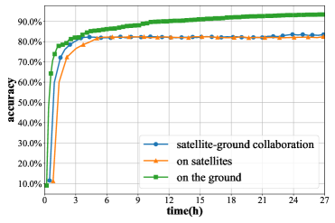
VI-B1 Training Time
The training time of the proposed framework is compared with two baselines as shown in Fig 8. It can be observed that the proposed framework achieves approximately reduction in training time when compared to the fine-tuning approach on satellites. This reduction in training time can be attributed to the fact that, in the proposed framework, the majority of the computation workload is handled by the PS, which operates at a much higher speed than the computing devices of the satellites. This highlights that when the model training cost is substantial, the time required for satellites to train the entire model locally often exceeds the time it takes to transmit training data between the GSs and the satellites. This discrepancy is primarily due to the limited processing power of the satellites, which makes local training less efficient. In contrast, by offloading the heavy computation tasks to the PS and only transmitting small training information, the proposed framework reduces the overall training time, thus optimizing the overall performance of the system.
VI-B2 Model Size
We also analyze the impact of different model sizes on the training efficiency of the proposed framework. The backbone network of our model is composed of several transformer blocks, and we conduct simulations by varying the number of these blocks. Specifically, these simulations are performed on the EuroSAT dataset, and the results are depicted in Fig. 9. The simulation results indicate that as the model size increases, the training time gap between our proposed framework and the traditional on-board training approach becomes progressively larger. The underlying reason is the increased computation demand in the backbone network as more transformer blocks are added. As the model size increases, a larger portion of the overall training process is accelerated on the PS, while the volume of data transmitted between the GSs and the satellites remains constant. This imbalance between local computation capacity and the model’s demands amplifies the advantage of offloading the computation to the GS, leading to a larger reduction in training time. This effect becomes even more pronounced as the model size increases, highlighting the scalability of the proposed framework.

VI-B3 The Overhead of Satellite-Ground Transmission
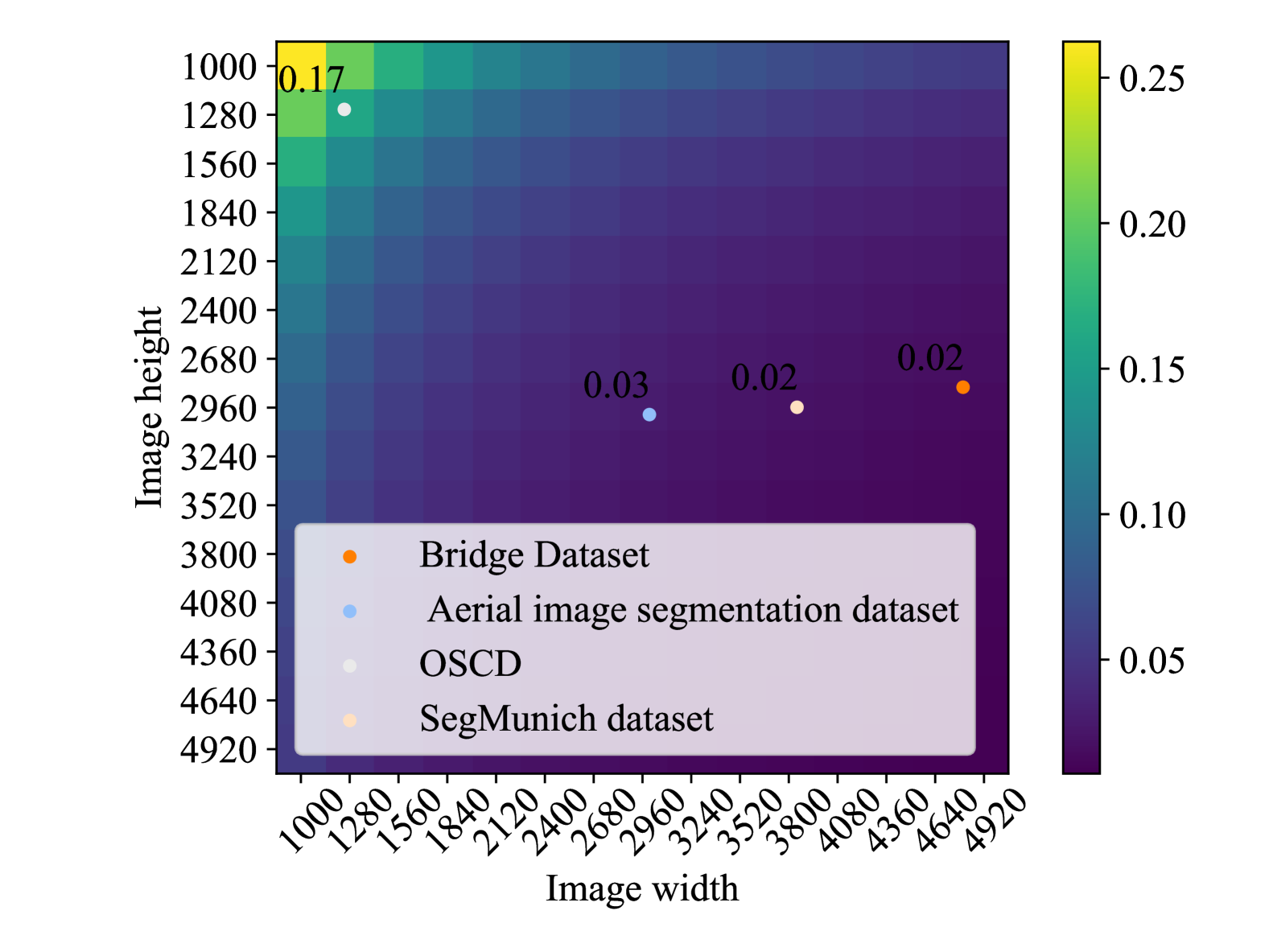
Intermittent SGLs can prevent data from being downloaded to the ground server in central training. To assess whether the proposed framework can effectively mitigate these issues, we conduct an analysis of the communication overhead. Specifically, we compare the communication overhead in our framework with the traditional approach of downloading the entire original dataset. For this comparison, we use several commonly used datasets in RS applications that cover a variety of domains, such as environmental monitoring and geospatial analysis. We simulate the data transmission requirements for both the traditional method of downloading the full dataset and our proposed framework that focuses on transmitting only model updates rather than raw data.
-
1.
Bridge dataset [39]. This dataset is for object detection and consists of 500 images, each containing at least one bridge from different regions worldwide. All images are pixels.
-
2.
Aerial image segmentation dataset [40]. This is used in image segmentation, where a semantic class label is assigned to each pixel as a basis for automatic map generation. Each image is approximately pixels.
-
3.
OSCD [41]. It contains 24 pairs of multispectral images taken between 2015 and 2018 and provides pairs of satellite images in 13 bands that can be used for change detection. The spatial resolution of the image varies between 10m, 20m, and 60m. The image size is pixels.
-
4.
SegMunich dataset [9]. It is used in previous simulations.
We present the results in Fig. 10. For datasets with 13 bands, we convert them into images with 3 bands of the same size to display them in the figure. The figure displays the ratio of the transmitted data size to the original data size when the original images vary in size. This ratio provides a clear indication of how much data is being transmitted between the satellite and the GS relative to the size of the original dataset. As the size of the original images increases, this ratio decreases, which can be attributed to the information extraction capability of the FMs. Several points in the figure are marked, each representing a specific scenario where the data transmission ratio is calculated for a given dataset. For example, in the simulations conducted on the SegMunich dataset, the transmitted data size is approximately of the size of the original dataset.
Given device parameters set as in Table I, the estimated data rate for downlinks is approximately , according to formulas in Section III-B. This data rate is insufficient for transmitting large volumes of raw data in a constellation. Consequently, directly transmitting raw data from the satellite to the ground server would result in significant delays, increased latency, and system performance bottlenecks. The proposed framework reduces the amount of data transmitted to the ground server, which alleviates the pressure on intermittent SGLs. Therefore, in certain scenarios where satellites continuously collect high-precision images daily and the data generation speed exceeds the transmission speed, the proposed framework proves more effective than traditional methods of downloading raw data.
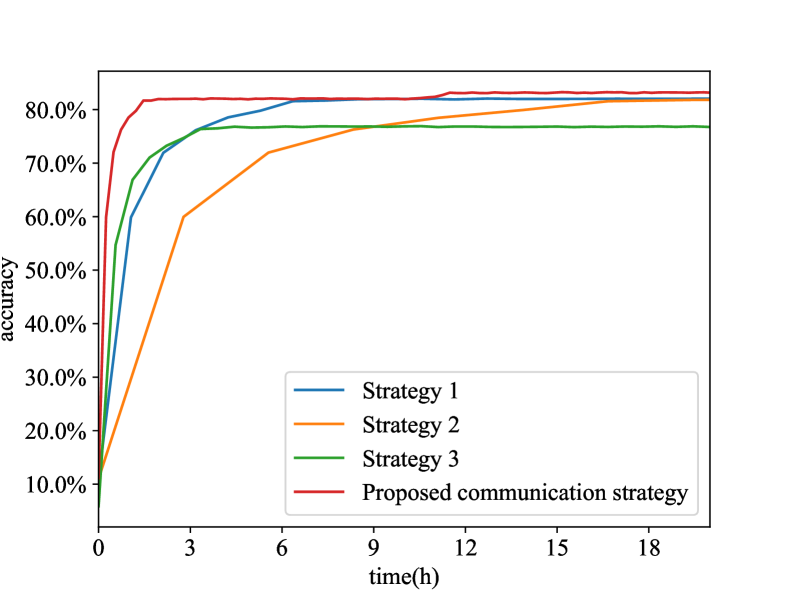
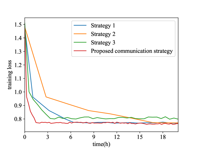
VI-B4 Communication Strategy
To verify the effective co-design of computing and communication in the proposed framework, we apply various inter-satellite and satellite-ground communication strategies.
-
1.
Strategy 1: Sequential intra-orbit transmission. In this strategy, intra-orbit data are first collected and aggregated by a designated satellite. Then, the satellite sends the collected data to other satellites in the same orbit via ISLs. Namely, data are transmitted sequentially in a specified direction until all satellites obtain . The total time required for this process is given by:
(30) where represents the time required to transmit data between two adjacent satellites. It can be observed that the total time increases linearly with the number of satellites.
-
2.
Strategy 2: Satellite-ground transmission without inter-satellite cooperation [17]. Each satellite only transmits local data until the PS receives all data.
-
3.
Strategy 3: Inter-orbit gossip transmission [26]. Each orbit only receives model parameters from two adjacent orbits and repeats the process for several rounds.
We can find that sequential intra-orbit transmission significantly reduces convergence speed compared to parallel transmission. In sequential transmission, after the computation is performed on each satellite, the data is transmitted sequentially. At any given moment, only one satellite is actively transmitting its data to the other satellite, while all other satellites remain idle. As a result, the overall system throughput is reduced, and the communication link is underutilized. Strategy 2 prolongs training time due to stragglers. In this strategy, the PS is required to wait for the slowest satellites to finish transmitting their model updates before starting the next training epoch. This creates a significant delay. For strategy 3, inter-orbit gossip transmission has a similar training time in each training round but needs more epochs to converge because all satellites do not reach a consensus on the global model in each epoch. These simulations demonstrate that the co-design of computing and communication plays a pivotal role in reducing latency, minimizing communication overhead, and accelerating the training process.
VII Conclusion
This paper proposed a satellite federated fine-tuning framework for RS FMs to addresses the training latency and computation resource constraints stemming from the limited computational capabilities of satellites, intermittent SGLs, and dynamic ISLs in Space-CPN. To tackle these issues, we designed a model partitioning and training scheme. We partition models into the embedding layer, the backbone network and the output layer and deploy the backbone networks and other components on the PS and satellites respectively to reduce on-board computation load and transmission burden. Furthermore, communication strategies for both satellite-ground and inter-satellite transmissions were co-designed with the training process to minimize latency. We put forward a topology-aware communication scheme, which assigns transmission tasks according to the real-time topological structure and the status of links. Regarding intra-orbit communication, considering the ring topology of each orbit, we present a parallel communication method founded on Ring Allreduce. As for inter-orbit communication, we design a communication algorithm that aims to reduce latency to the minimum by taking link capacity into account. These strategies blend communication and computational procedures, factoring in aspects such as restricted bandwidth, sparse connectivity, and dynamic topologies. As a result, these strategies enhance the efficiency of data transmission and expedite the convergence of models. Simulation results validate the effectiveness of our proposed framework and communication strategies.
References
- [1] S. Fang, L. D. Xu, Y. Zhu, J. Ahati, H. Pei, J. Yan, and Z. Liu, “An integrated system for regional environmental monitoring and management based on internet of things,” IEEE Trans. Ind. Informat., vol. 10, no. 2, pp. 1596–1605, 2014.
- [2] A. Temenos, N. Temenos, M. Kaselimi, A. Doulamis, and N. Doulamis, “Interpretable deep learning framework for land use and land cover classification in remote sensing using SHAP,” IEEE Geosci. Remote Sens. Lett., vol. 20, pp. 1–5, 2023.
- [3] A. Xiao, W. Xuan, J. Wang, J. Huang, D. Tao, S. Lu, and N. Yokoya, “Foundation models for remote sensing and earth observation: A survey,” 2024. [Online]. Available: https://arxiv.org/abs/2410.16602
- [4] A. Das and S. Chandran, “Transfer learning with Res2Net for remote sensing scene classification,” in Proc. Int. Conf. Cloud Comput., Data Sci. Eng. (Confluence), 2021, pp. 796–801.
- [5] A. Dosovitskiy, L. Beyer, A. Kolesnikov, D. Weissenborn, X. Zhai, T. Unterthiner, M. Dehghani, M. Minderer, G. Heigold, S. Gelly et al., “An image is worth 16x16 words: Transformers for image recognition at scale,” arXiv preprint arXiv:2010.11929, 2020.
- [6] J. Jakubik, S. Roy, C. Phillips, P. Fraccaro, D. Godwin, B. Zadrozny, D. Szwarcman, C. Gomes, G. Nyirjesy, B. Edwards et al., “Foundation models for generalist geospatial artificial intelligence,” arXiv preprint arXiv:2310.18660, 2023.
- [7] Y. Cong, S. Khanna, C. Meng, P. Liu, E. Rozi, Y. He, M. Burke, D. B. Lobell, and S. Ermon, “SatMAE: Pre-training transformers for temporal and multi-spectral satellite imagery,” in Proc. Adv. Neural Inf. Process. Syst. (NeurIPS), vol. 35, 2022, pp. 197–211.
- [8] M. Noman, M. Naseer, H. Cholakkal, R. M. Anwar, S. Khan, and F. S. Khan, “Rethinking transformers pre-training for Multi-Spectral satellite imagery,” in Proc. IEEE/CVF Conf. Comput. Vis. Pattern Recognit. (CVPR), 2024, pp. 27 811–27 819.
- [9] D. Hong, B. Zhang, X. Li, Y. Li, C. Li, J. Yao, N. Yokoya, H. Li, P. Ghamisi, X. Jia, A. Plaza, P. Gamba, J. A. Benediktsson, and J. Chanussot, “SpectralGPT: Spectral remote sensing foundation model,” IEEE Trans. Pattern Anal. Mach. Intell., vol. 46, no. 8, pp. 5227–5244, 2024.
- [10] H. Chen, M. Xiao, and Z. Pang, “Satellite-Based computing networks with federated learning,” IEEE Wireless Commun., vol. 29, no. 1, pp. 78–84, 2022.
- [11] K. B. Letaief, Y. Shi, J. Lu, and J. Lu, “Edge artificial intelligence for 6g: Vision, enabling technologies, and applications,” IEEE J. Sel. Areas Commun., vol. 40, no. 1, pp. 5–36, 2022.
- [12] Y. Shi, L. Zeng, J. Zhu, Y. Zhou, C. Jiang, and K. B. Letaief, “Satellite federated edge learning: Architecture design and convergence analysis,” IEEE Trans. Wireless Commun., vol. 23, no. 10, pp. 15 212–15 229, 2024.
- [13] Y. Tian, Y. Wan, L. Lyu, D. Yao, H. Jin, and L. Sun, “FedBERT: When federated learning meets pre-training,” ACM Trans. Intell. Syst. Technol., vol. 13, no. 4, pp. 1–26, Aug. 2022.
- [14] Z. Wang, Y. Zhou, Y. Shi, and K. B. Letaief, “Federated Fine-Tuning for Pre-Trained foundation models over wireless networks,” IEEE Trans. Wireless Commun., vol. 24, no. 4, pp. 3450–3464, 2025.
- [15] J. Lin, J. Xu, Y. Li, and Z. Xu, “Federated learning with dynamic aggregation based on connection density at satellites and ground stations,” in Proc. IEEE Int. Conf. Satellite Comput. (Satellite), 2022, pp. 31–36.
- [16] Y. Wang, C. Zou, D. Wen, and Y. Shi, “Federated learning over LEO satellite,” in Proc. IEEE Globecom Workshops (GC Wkshps), 2022, pp. 1652–1657.
- [17] N. Razmi, B. Matthiesen, A. Dekorsy, and P. Popovski, “Ground-Assisted federated learning in LEO satellite constellations,” IEEE Wireless Commun. Lett., vol. 11, no. 4, pp. 717–721, 2022.
- [18] Z. Lin, Z. Chen, Z. Fang, X. Chen, X. Wang, and Y. Gao, “FedSN: A federated learning framework over heterogeneous LEO satellite networks,” IEEE Trans. Mobile Comput., vol. 24, no. 3, pp. 1293–1307, 2025.
- [19] L. Wu and J. Zhang, “FedGSM: Efficient federated learning for LEO constellations with gradient staleness mitigation,” in Proc. IEEE Int. Workshop Signal Process. Adv. Wireless Commun. (SPAWC), 2023, pp. 356–360.
- [20] M. Elmahallawy and T. Luo, “FedHAP: Fast federated learning for LEO constellations using collaborative HAPs,” in Proc. Int. Conf. Wireless Commun. Signal Process. (WCSP), 2022, pp. 888–893.
- [21] N. Razmi, B. Matthiesen, A. Dekorsy, and P. Popovski, “On-Board federated learning for satellite clusters with Inter-Satellite links,” IEEE Trans. Commun., vol. 72, no. 6, pp. 3408–3424, 2024.
- [22] M. Elmahallawy and T. Luo, “AsyncFLEO: Asynchronous federated learning for LEO satellite constellations with High-Altitude platforms,” in Proc. IEEE Int. Conf. Big Data (Big Data), 2022, pp. 5478–5487.
- [23] C. Wu, Y. Zhu, and F. Wang, “DSFL: Decentralized satellite federated learning for Energy-Aware LEO constellation computing,” in Proc. IEEE Int. Conf. Satellite Comput. (Satellite), 2022, pp. 25–30.
- [24] Z. Tang, S. Shi, B. Li, and X. Chu, “GossipFL: A decentralized federated learning framework with sparsified and adaptive communication,” IEEE Trans. Parallel Distrib. Syst., vol. 34, no. 3, pp. 909–922, 2023.
- [25] Z. Zhai, Q. Wu, S. Yu, R. Li, F. Zhang, and X. Chen, “FedLEO: An Offloading-Assisted decentralized federated learning framework for low earth orbit satellite networks,” IEEE Trans. Mobile Comput., vol. 23, no. 5, pp. 5260–5279, 2024.
- [26] M. Yang, J. Zhang, and S. Liu, “DFedSat: Communication-efficient and robust decentralized federated learning for leo satellite constellations,” arXiv preprint arXiv:2407.05850, 2024.
- [27] Z. Yan and D. Li, “Convergence time optimization for decentralized federated learning with LEO satellites via number control,” IEEE Trans. Veh. Technol., vol. 73, no. 3, pp. 4517–4522, 2024.
- [28] Q. Chen, L. Yang, Y. Zhao, Y. Wang, H. Zhou, and X. Chen, “Shortest path in LEO satellite constellation networks: An explicit analytic approach,” IEEE J. Sel. Areas Commun., vol. 42, no. 5, pp. 1175–1187, 2024.
- [29] H. B. McMahan, E. Moore, D. Ramage, S. Hampson, and B. A. y Arcas, “Communication-Efficient learning of deep networks from decentralized data,” in Proc. Int. Conf. Artif. Intell. Stat. (AISTATS), 2017, pp. 1273–1282.
- [30] X. Gao, R. Liu, and A. Kaushik, “An energy efficient approach for service chaining placement in satellite ground station networks,” in Proc. Int. Wireless Commun. Mobile Comput. Conf. (IWCMC), 2021, pp. 217–222.
- [31] Z. Xia, Y. Lin, C. Hu, and X. Bu, “Inter-Satellite link channel characterization of laser communication systems,” in Proc. IEEE Int. Conf. Inf., Commun. Netw. (ICICN), 2023, pp. 426–431.
- [32] A. Polishuk and S. Arnon, “Optimization of a laser satellite communication system with an optical preamplifier,” JOSA A, vol. 21, no. 7, pp. 1307–1315, Jul. 2004.
- [33] B. Shang, S. Zhang, and Z. J. Wong, “Channel modeling and rate analysis of optical inter-satellite link (OISL),” arXiv preprint arXiv:2501.02756, 2025.
- [34] G. Wang, F. Yang, J. Song, and Z. Han, “Free space optical communication for Inter-Satellite link: Architecture, potentials and trends,” IEEE Commun. Mag., vol. 62, no. 3, pp. 110–116, 2024.
- [35] I. Leyva-Mayorga, B. Soret, and P. Popovski, “Inter-plane inter-satellite connectivity in dense LEO constellations,” IEEE Trans. Wireless Commun., vol. 20, no. 6, pp. 3430–3443, 2021.
- [36] Z. Na, Q. Guan, C. Fu, Y. Cui, and Q. Guo, “Channel model and throughput analysis for LEO OFDM satellite communication system,” Int. J. Future Gener. Commun. Netw., vol. 6, no. 6, pp. 109–122, 2013.
- [37] K. Zhang, S. Yang, Y. Wang, J. Huang, and C.-X. Wang, “Ray-Tracing based channel modeling and characteristics analysis for LEO satellite-to-ground systems,” in Proc. Eur. Conf. Antennas Propag. (EuCAP), 2024, pp. 1–5.
- [38] P. Helber, B. Bischke, A. Dengel, and D. Borth, “EuroSAT: A novel dataset and deep learning benchmark for land use and land cover classification,” IEEE J. Sel. Top. Appl. Earth Obs. Remote Sens., vol. 12, no. 7, pp. 2217–2226, 2019.
- [39] K. Nogueira, C. Cesar, P. H. T. Gama, G. L. S. Machado, and J. A. dos Santos, “A tool for bridge detection in major infrastructure works using satellite images,” in Proc. Workshop Comput. Vis. (WVC), 2019, pp. 72–77.
- [40] P. Kaiser, J. D. Wegner, A. Lucchi, M. Jaggi, T. Hofmann, and K. Schindler, “Learning aerial image segmentation from online maps,” IEEE Trans. Geosci. Remote Sens., vol. 55, no. 11, pp. 6054–6068, 2017.
- [41] R. C. Daudt, B. Le Saux, A. Boulch, and Y. Gousseau, “Urban change detection for multispectral earth observation using convolutional neural networks,” in Proc. IEEE Int. Geosci. Remote Sens. Symp. (IGARSS), 2018, pp. 2115–2118.