Experimental realization and synchronization of a quantum van der Pol oscillator
Abstract
Classical self-sustained oscillators, that generate periodic motion without periodic external forcing, are ubiquitous in science and technology. The realization of nonclassical self-oscillators is an important goal of quantum physics. We here present the experimental implementation of a quantum van der Pol oscillator, a paradigmatic autonomous quantum driven-dissipative system with nonlinear damping, using a single trapped atom. We demonstrate the existence of a quantum limit cycle in phase space in the absence of a drive and the occurrence of quantum synchronization when the nonlinear oscillator is externally driven. We additionally show that synchronization can be enhanced with the help of squeezing perpendicular to the direction of the drive and, counterintuitively, linear dissipation. We also observe the bifurcation to a bistable phase-space distribution for large squeezing. Our results pave the way for the exploration of self-sustained quantum oscillators and their application to quantum technology.
The van der Pol oscillator is a prototypical self-sustained oscillator with nonlinear friction [1]. Due to its versatility, it has played a central role in the theory of nonlinear oscillations [2, 3], the exploration of chaotic dynamics [4, 5] and the study of synchronization [6, 7]. The nonlinear damping is such that the van der Pol oscillator is supplied with energy for small amplitudes, while energy is dissipated for large amplitudes. Self-oscillations hence occur in the absence of any external force, and the system asymptotically tends to a limit cycle [2, 3]. Self-sustained oscillators differ from ordinary nonlinear systems, since they cannot be analyzed using quasilinear methods. Periodic forcing of the van der Pol oscillator leads to chaotic attractors owing to the nontrivial competition between external cyclic driving and internal autonomous oscillations [4, 5]. Its limit cycle can additionally be entrained by a weak periodic signal, inducing synchronized oscillations [6, 7].
Theoretical research has recently focused on the quantum version of the van der Pol oscillator [8, 9, 10, 11, 12, 13, 14, 15, 16, 17, 18, 19, 20, 21], a canonical nonlinear model of driven-dissipative open quantum systems [22, 23, 24]. The tunable interplay of coherent drive and incoherent dissipation in these systems generates complex nonequilibrium evolution and nontrivial steady states [22, 23, 24], which make them interesting for quantum technological applications [25]. The presence of nonlinearities in general and of self-sustained oscillations in particular further increase the complexity of the dynamics [16]. The properties of quantum and classical van der Pol oscillators usually strongly differ due to the effects of quantum fluctuations and quantum coherence [8, 9, 10, 11, 12, 13, 14, 15, 16, 17, 18, 19, 20, 21]. Quantum noise is thus expected to hinder quantum synchronization [9], while squeezing [15] and dissipation [18] are predicted to enhance it. A squeezed drive should also lead to quantum metastability associated with large timescale separations in the dynamics [21]. Even though the van der Pol oscillator [26] has been introduced the same year as Schrödinger’s equation [27], its quantum implementation has remained elusive.
We here experimentally realize a quantum van der Pol oscillator using a single Ca+ ion in a Paul trap [28] using reservoir engineering techniques [29]. We analyze both the undriven and the forced nonlinear quantum oscillator, as well as the influence of squeezing. In the undriven case, we observe the approach to a quantum limit cycle in phase space by reconstructing [30] the evolution of the Wigner function [31]. We further demonstrate the occurrence of stable phase synchronization to an external drive [8], and determine the corresponding Arnold tongue diagram [18]. We also find that synchronization is enhanced by linear dissipation in the deep quantum regime, a behavior that is absent in the classical and quantum domains [18]. Finally, we show that squeezing applied perpendicularly to the drive in phase space induces a bifurcation of the steady-state Wigner function, and that it additionally increases phase synchronization [15].
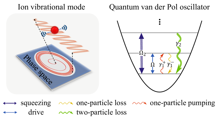
Experimental system. We experimentally implement a quantum van der Pol oscillator whose dynamics can be described by the master equation (in units of ) [8, 9, 10, 11, 12, 13, 14, 15, 16, 17, 18, 19, 20, 21]
| (1) |
where is the coherent Hamiltonian (with detuning ), including the displacement drive (with strength ) and squeezing drive in the rotating frame (with amplitude ); the parameter is the relative phase between the two drives. The operators and are the usual ladder operators of the harmonic oscillator, and the Lindblad dissipators are given by . The two coefficients and respectively represent the one-particle pumping rate and the one-particle loss rate (associated with linear damping), while is the two-particle loss rate (corresponding to nonlinear damping) (Fig. 1). Equation (1) differs from recent ion-trap realizations of self-excited phonon lasers [32, 33] through the presence of nonlinear friction. It exhibits distinct regimes depending on the relative dissipation rates: semiclassical for , quantum for , and deep quantum for [18]. Our study primarily focuses on the latter two, where the phonon population remains low and the system displays nonclassical properties.
The experiment uses the axial motion of a single trapped ion as the harmonic oscillator with a trapping frequency . The internal spin states are defined as , , and to assist laser induced spin-motion couplings with a narrow-linewidth 729 nm laser along the axial direction. The displacement drive in Eq. (1) is achieved through a radio-frequency signal at frequency applied to one of the trap electrodes [34]. Linear and nonlinear damping processes are further realized by reservoir engineering methods [29], coupling the oscillator to the spin such that and , with the spin optically pumped back to , effectively forming the motional dissipation with respective strengths of and (Supplementary Information). We additionally implement squeezing with controllable strength by applying two pairs of laser tones off-resonantly driving the spin-motion joint transition [35]. After Doppler and ground state cooling of the motion [28], the displacement drive is then applied continuously, while other coupling and pumping lasers are applied sequentially via a first-order Trotterization approach [36]. Eventually, we investigate the properties of the quantum van der Pol oscillator via tomographic state reconstruction that maps the oscillator’s motional information onto spin populations, and thus directly measures the Wigner function in polar coordinates [30].
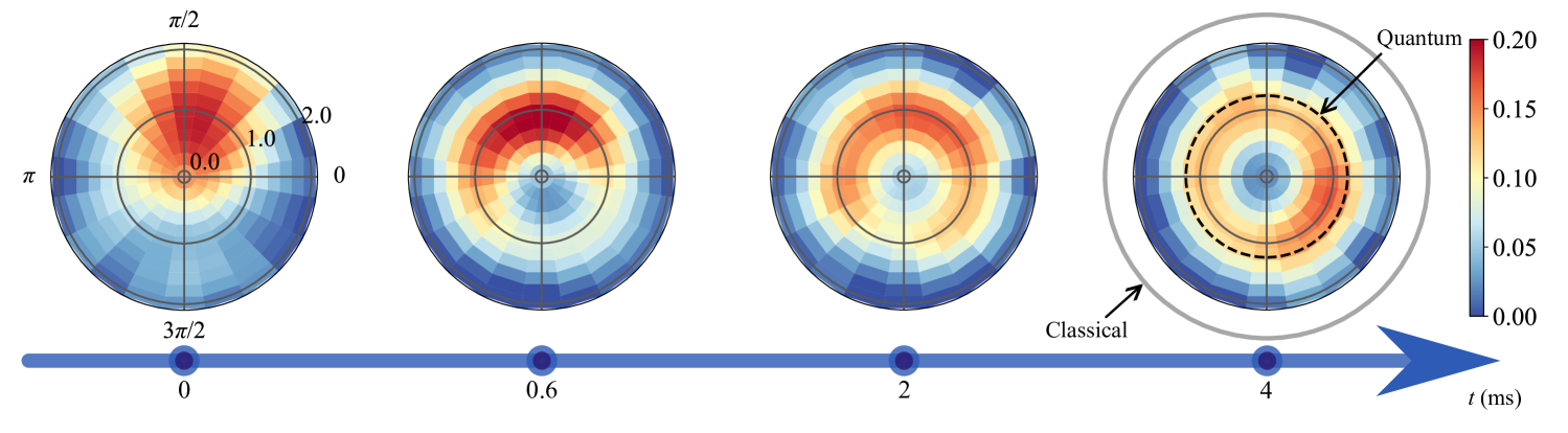
Quantum limit cycle and synchronization. Let us begin by analyzing the dynamics of the undriven van der Pol oscillator, where . To that end, we prepare the oscillator in a displaced thermal state [37], that is, a thermal state with mean phonon number displaced by a coherent state with amplitude , and measure the Wigner function at times 0, 600, 2000, and 4000 s for (Fig. 2), with . We observe that the initially localized state first relaxes to a lower amplitude before spreading in phase space to form the typical ring shape of a limit cycle [8]. This establishes the autonomous nature of the oscillations. We further note that the radius of the quantum ring (black dashed) is a factor two smaller than the radius of the corresponding classical limit cycle (gray solid) [1], highlighting its nonclassical nature [19].
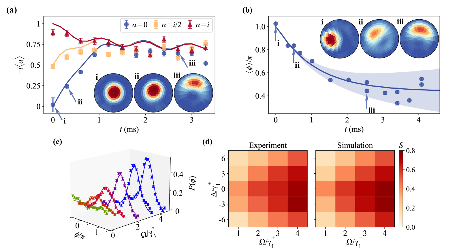
We next switch on the resonant coherent drive with amplitude according to Eq. (1), oriented along the direction (). The temporal evolution of the average amplitude of the oscillator is measured for various initial conditions, , for and (Fig. 3a). For all these initial conditions, the mean amplitude converges to the same steady oscillations as the van der Pol oscillator adjusts itself to the external drive, indicating entrainment between the two [1]. The inset further shows that the drive breaks the radial symmetry of the undriven limit cycle, aligning the oscillator’s phase-space distribution with the drive axis. Additional insight is obtained by examining the phase dynamics of an initial coherent state with a phase offset relative to the drive (Fig. 3b): the mean phase locks to a constant value close to (Fig. 3b), a hallmark of phase synchronization [8]. The shaded blue area accounts for experimental imperfections, including oscillator frequency and laser frequency fluctuations. Experimental results align closely with numerical simulations (solid lines), with minor deviations (e.g., a slight phase misalignment) attributable to off-resonance effects caused by the sideband transitions (Supplementary Information). Figure 3c moreover reveals that the phase distribution, , adopts a Gaussian profile, centered at the drive phase, that becomes narrower with increasing driving strength ().
To quantify phase synchronization, we use the mean resultant length of a circular distribution, [18]. It takes the value 0 for an unsynchronized state and the value 1 for a perfectly synchronized state, which corresponds to a delta Wigner function. We examine the synchronization parameter as a function of driving strength and detuning , while keeping the dissipative rate fixed at (Fig. 3d). We find that synchronization increases with the driving strength and decreases with the detuning, as expected. We recognize a structure which is reminiscent of an Arnold tongue which defines the synchronized domain of classical synchronization phenomena [6, 7]. Figure 3d shows that phase locking of the quantum van der Pol oscillator is a robust phenomenon that appears in a large region of parameter space. We again have good agreement with numerical simulations. As before, there is a slight asymmetry in the diagram due to experiment imperfections.
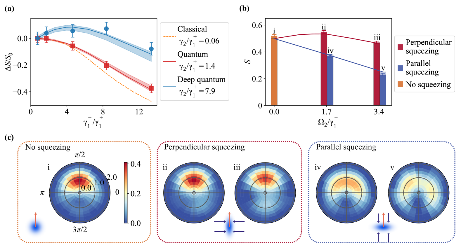
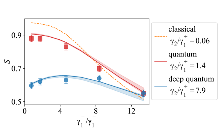
Quantum dissipation boost and squeezing. Quantum noise is usually expected to be detrimental for synchronization as it provides an additional source of phase diffusion [9]. It is therefore essential to identify quantum mechanisms that allow one to boost synchronization in the quantum realm. We first investigate the influence of single-phonon dissipation by increasing the parameter in three different regimes defined by the strength of the nonlinear damping [18]: (deep quantum regime), (quantum regime) and (semiclassical regime). The external drive is resonant with the oscillator’s frequency, with a strength of . Values of are needed to avoid strong decoherence. We observe in Fig. 4a that increasing single-phonon dissipation enhances synchronization () in the deep quantum regime (blue dots), but reduces it in the quantum (red squares) and semiclassical (yellow line) regimes; the small domain is not accessible experimentally and hence simulated. This dramatic difference can be explained by noting that the decoherence rate grows with the phonon number [18], meaning that higher levels decohere faster. By driving the oscillator to lower levels, single-phonon dissipation thus initially helps increase the transition rate between the two lowest levels, that is, build up coherence between and , which in turn, augments synchronization. Larger single-phonon dissipation suppresses quantum synchronization () in all regimes, as dissipation-induced decoherence becomes dominant.
Another strategy to counteract the negative influence of quantum noise, and augment synchronization, is squeezing [15]. Squeezing is indeed able to suppress fluctuations in one direction, at the expense of the orthogonal direction. Figure 4c shows the reconstructed Wigner function for three values of the squeezing strength (), when the squeezing direction is either parallel () or perpendicular () to the direction of the displacement drive; the dissipative parameter is here and the resonant driving strength is . The shape of the Wigner function results from the competition between the displacement drive and the squeezing drive. For small squeezing strengths, the Wigner function remains primarily aligned with the displacement direction. However, as the squeezing amplitude increases, and exceeds the displacement strength, the Wigner function splits, signaling the bifurcation from a monostable distribution to a bistable distribution [21]. Small squeezing perpendicular to the drive () reduces the phase variance, thus enhancing synchronization, as seen in the increase of the mean resultant length in Fig. 4c; this effect could be further improved by optimizing the alignment between the two drives. By contrast, small squeezing parallel to the drive () increases the phase variance, which hinders synchronization. In both instances, a larger squeezing parameter, beyond the bifurcation to multistability, reduces the mean resultant length , beyond the level achieved without squeezing. One may hence conclude that there is an optimal parameter window in which squeezing has a positive effect on quantum synchronization, for instance shown in Fig. 4b.
Conclusion. Driven-dissipative quantum systems are significantly influenced by the dissipative part of the dynamics, rather than by their Hamiltonian, and therefore exhibit properties drastically different from those of closed systems at equilibrium. By engineering nonlinear dissipation, we have demonstrated the experimental realization of an autonomous quantum van der Pol oscillator using a single trapped ion. Our results offer key insights into quantum limit cycles, phase synchronization, and the interplay between coherence, dissipation and squeezing. They thus provide a valuable platform to investigate the intricate dynamics of quantum self-sustained oscillators. They could, for example, be harnessed for applications in quantum sensing [17], quantum computation and communication [25], or improve the control and manipulation of quantum states [38]. Moreover, adding higher-order nonlinear drives could enable the exploration of exotic quantum phases [39], while extensions to networks of nonlinear oscillators could reveal novel collective phenomena and dissipative phase transitions [40]. These systems thus hold immense potential for advancing quantum technologies and deepening our understanding of nonequilibrium quantum dynamics.
We thank Yangchao Shen for helpful discussion. The USTC team acknowledges support from the National Natural Science Foundation of China (Grant No. 92165206) and the Innovation Program for Quantum Science and Technology (Grant No. 2021ZD0301603). Jun Li acknowledges support from the National Natural Science Foundation of China (Grant No. 12441502 and No. 12122506), the Shenzhen Science and Technology Program (RCYX20200714114522109). Xiaodong Yang acknowledges support from the National Natural Science Foundation of China (Grant No. 12204230). Eric Lutz is supported by the German Science Foundation DFG (Grant No. FOR 2724).
Supplementary Materials for:
“Experimental realization and synchronization of a quantum van der Pol oscillator”
Appendix A Experimental scheme
We demonstrate the quantum van der Pol oscillator through the Trotterization approach [36]: the target evolution is divided into steps, each consisting of coherent operations and dissipative operations , implemented alternately. The total operations can then mimic the original process: . The schematic of the circuit is shown in Fig. S1.
For the coherent part, a radio-frequency (RF) signal with frequency is applied to one of the electrodes to generate the displacement driving [34]. This is the only component always applied during the sequence, other parts are implemented sequentially. We introduce phonon squeezing along the controllable direction and strength by laser driving two non-commuting spin-dependent forces [35].
For the dissipative part, the internal spins are introduced as the dissipative channel to engineer the desired jump operators through sideband transitions and spin reset. Since the three dissipation channels, including , and , undergo the similar operation, we only take as an example. Considering the spin-phonon system whose initial state is , the red sideband Hamiltonian is
| (S1) |
where is the Rabi frequency of the first-order red sideband. After sideband transition time , the density matrix for the oscillator is
| (S2) | ||||
For small times , we can expand the unitary operators as and obtain
| (S3) | ||||
where . After the spin reset, the density matrix of the oscillator would become , which undergoes the same trajectory as with effective pumping rate .
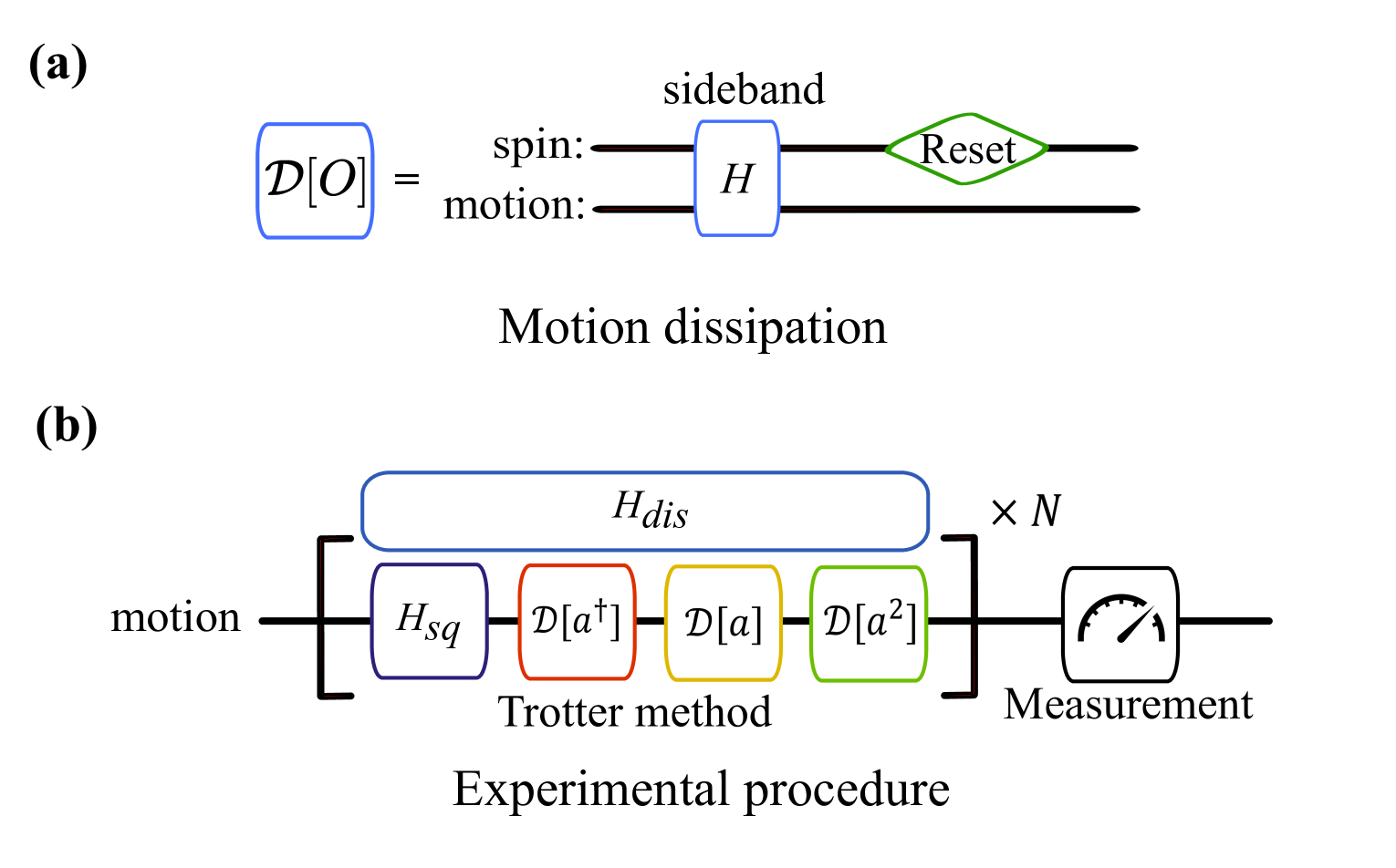
In the experiment, we sequentially apply coherent and dissipative operations similar to above for respective duration ’s. The first-order Trotterization is applied as shown in Fig. S1, where each coherent or Lindblad operator is applied once for each cycle of duration . As a result, the averaged strength of these drives in the Trotterization process needs to be rescaled with a factor . Thus, the effective dissipative rate for is
| (S4) |
For the other dissipative and coherent operators, we similarly obtain
| (S5) | ||||
where represent the Rabi frequency of first-order blue sideband, second-order red sideband and squeezing respectively, are the corresponding pulse time.
Appendix B Experimental apparatus and procedure
In this work, we use a single trapped ion in a linear Paul trap [28]. The quadrupole transition between and is used for coherent manipulations, which is driven by a narrow-linewidth 729 nm laser along the axial direction. The Lamb-Dicke parameter for the spin-motion coupling is . As the experiment is performed mostly in the (deep) quantum regime, the phonon is at most excited to 4, which means that the experiments can be well described by the Lamb-Dicke approximation [28]. The internal electronic state of the ion is initialized to by the frequency-resolved 729 nm laser combined with 854 nm and 866 nm repump lasers. We use the 397 nm cycling transition between and along with 866 nm repump laser for fluorescence detection.
The axial mode is used to simulate the van der Pol oscillator. Its frequency is measured by “tickle” spectroscopy, where we apply the radio frequency to one electrode and detect the resulting phonon population using the red sideband. We calibrate it every 30 minutes to ensure the long-term stability of the mode frequency within 30 Hz.
Before each experiment, the motional mode is initialized by Doppler cooling and sideband cooling. After sideband cooling, the mean phonon number of the mode can be cooled to less than 0.1. The subsequent experimental procedure involves phonon state preparation (if necessary), dynamic evolution and mode measurement. We prepare the coherent thermal state using an electronic displacement drive, combined with Trotterizations involving blue and red sidebands to simulate the heating process. During the dynamic evolution process, the external drive remains on (except for Fig. 2) throughout the entire evolution. The other operations are segmented. In each cycle, we sequentially apply squeezing (if necessary), one-particle pumping, one-particle loss (if necessary), two-particle loss, and spin state preparation. The state preparation is added to avoid the leakage to . The phonon tomography is done right after the evolution. The whole procedure is shown in Fig. S1b and on Tab. S1. Key effective intensity parameters for the experiments are listed in Tab. S2. The pulse time and number of cycles are shown in Tab. S3.
| Experimental procedure |
| 1. Doppler cooling and sideband cooling |
| 2. Spin state preparation |
| 3*. Prepare the initial state of phonon |
| 4*. Open the external drive |
| 5*. Squeezing drive |
| 6. One-particle pumping |
| 7*. One-particle loss |
| 8. Two-particle loss |
| 9. Spin state preparation |
| 10. Repeat Step 5-9 for N times |
| 11. Close the external drive |
| 12. Phonon measurement |
| Figure | [kHz] | [kHz] | heating rate [kHz] | [kHz] | [Hz] | [Hz] | [Hz] | |||
| Fig.2 | 2.06 | 0.09 | 0.09 | 1.11 | 0 | 0 | 0 | |||
| Fig.3a | 0.28 | 0.12 | 0.12 | 1.48 | 160 | 0 | 0 | |||
| Fig.3b | 0.23 | 0.09 | 0.09 | 1.31 | 173 | 0 | 0 | |||
| Fig.3c | 0.23 | 0.09 | 0.09 | 1.31 |
|
0 | 0 | |||
| Fig.3d | 0.28 | 0.12 | 0.12 | 1.48 |
|
0 |
|
|||
| Fig.4a quantum | 0.16 |
|
0.12 | 0.22 | 76 | 0 | 0 | |||
| Fig.4a deep quantum | 0.16 |
|
0.12 | 1.25 | 76 | 0 | 0 | |||
| Fig.4b-c | 0.23 | 0.12 | 0.12 | 1.01 | 43 |
|
0 |
| Figure | [] | [] | [] | [] | [] | [] | [] | ||
| Fig.2 | 40 | 0 | 150 | 0 | 10 | 0 | 200 |
|
|
| Fig.3a | 10 | 0 | 120 | 0 | 10 | 10 | 150 |
|
|
| Fig.3b | 10 | 0 | 150 | 0 | 10 | 0 | 170 |
|
|
| Fig.3c | 10 | 0 | 150 | 0 | 10 | 0 | 170 | 20 | |
| Fig.3d | 10 | 0 | 120 | 0 | 10 | 10 | 150 | 48 | |
| Fig.4a-b quantum | 5 | 10 | 50 | 0 | 15 | 80 | 160 | 37 | |
| Fig.4a-b deep quantum | 5 | 10 | 120 | 0 | 15 | 10 | 160 | 37 | |
| Fig.4c-d | 10 | 0 | 150 | 35 | 15 | 10 | 220 | 20 |
Appendix C Numerical Simulations and Experimental Imperfections
We simulate the experimental sequence by modeling a two-level system coupled to a phonon mode truncated at 30 excitations. We use the full Hamiltonian instead of a simple linear expansion for the interaction between spin and motion. As will be discussed below, this gives rise to the motion phase shift caused by the off-resonant coupling of the sideband transitions. These simulations are performed using the QuTip toolbox [41]. The simulation lines shown in the main text all consider the real experimental issues, including heating rate of phonon and full Hamiltonian of spin-motion couplings. The other imperfections are mainly due to the trapping frequency fluctuation, which is shown as the shadow region in the figures.
Another key experimental issue is the unavoidable off-resonant coupling effect caused the second red sideband transition, which is used in conjunction with spin pumping to implement the two-phonon dissipator . Due to the small Lamb-Dicke parameter, additional coupling to the first red sideband and carrier cannot be neglected. A second-order Magnus expansion shows that this off-resonant interaction generates an effective phonon AC Stark shift, , causing a slight shift in the steady-state phase relative to the external drive and minor oscillations during evolution. Nevertheless, these off-resonant effects have only a minimal impact on the mean resultant length compared to the ideal case. In addition, the heating rate of the mode is around 80-150 phonon/s (drift from month to month), which is modeled as jump operators and .
The Hamiltonians for the numerical simulation in QuTip are provided below. Motion heating is modeled using this master equation:
| (S6) |
The Hamiltonian includes , displacement drive and spin-motion coupling Hamiltonians, which are listed below, with .
First-order blue sideband:
| (S7) |
First-order red sideband:
| (S8) |
Second-order red sideband:
| (S9) |
Squeezing :
| (S10) | ||||
Appendix D Original data for dissipative enhanced synchronization
The original data for Fig. 4(a) in the main text is shown in Fig. S2, together with the numerical simulations. The synchronization parameter of the deep quantum case is always smaller than the quantum regime, which is due to the larger quantum noise. The experimental data is slightly below the simulation line, which may due to the extra decoherence of motion, especially for the quantum regime cases.
References
- [1] Jenkins, A. Self-oscillation. Phys. Rep. 525, 167-222 (2013).
- [2] Nayfeh, A. H. & Mook, D. T. Nonlinear Oscillations. (John Wiley & Sons, New York, NY, USA, 1979).
- [3] Guckenheimer, J. & Holmes, P. Nonlinear Oscillations, Dynamical Systems, and Bifurcations of Vector Fields. (Springer, New York, NY, USA, 1983).
- [4] Strogatz, S. H. Nonlinear Dynamics and Chaos: With Applications to Physics, Biology, Chemistry, and Engineering. (CRC Press, Boca Raton, FL, USA, 2015).
- [5] Thompson, J. M. T. & Stewart, H. B. Nonlinear Dynamics and Chaos. (John Wiley & Sons, New York, NY, USA, 2002).
- [6] Pikovsky, A., Rosenblum, M. & Kurths, J. Synchronization: A Universal Concept in Nonlinear Sciences. (Cambridge University Press, Cambridge, UK, 2001).
- [7] Osipov, G. V., Kurths, J. & Zhou, C. Synchronization in Oscillatory Networks. (Springer, Berlin, Heidelberg, Germany, 2007).
- [8] Lee, T. E. & Sadeghpour, H. R. Quantum Synchronization of Quantum van der Pol Oscillators with Trapped Ions. Phys. Rev. Lett. 111, 234101 (2013).
- [9] Walter, S., Nunnenkamp, A. & Bruder, C. Quantum Synchronization of a Driven Self-Sustained Oscillator. Phys. Rev. Lett. 112, 094102 (2014)
- [10] Lee, T. E., Chan, C.-K. & Wang, S. Entanglement tongue and quantum synchronization of disordered oscillators. Phys. Rev. E 89, 022913 (2014)
- [11] Walter, S., Nunnenkamp, A. & Bruder, C. Quantum synchronization of two Van der Pol oscillators. Ann. Phys. 527, 131-138 (2015).
- [12] Ameri, V. et al. Mutual information as an order parameter for quantum synchronization. Phys. Rev. A 91, 012301 (2015).
- [13] Lörch, N. et al. Genuine Quantum Signatures in Synchronization of Anharmonic Self-Oscillators. Phys. Rev. Lett. 117, 073601 (2016).
- [14] Weiss, T., Walter, S. & Marquardt, F. Quantum-coherent phase oscillations in synchronization. Phys. Rev. A 95, 041802 (2017).
- [15] Sonar, S. et al. Squeezing Enhances Quantum Synchronization. Phys. Rev. Lett. 120, 163601 (2018).
- [16] Scarlatella, O., Clerk, A. A. & Schiro, M. Spectral functions and negative density of states of a driven-dissipative nonlinear quantum resonator. New J. Phys. 21, 043040 (2019).
- [17] Dutta, S. & Cooper, N. R. Critical Response of a Quantum van der Pol Oscillator. Phys. Rev. Lett. 123, 250401 (2019).
- [18] Mok, W.-K., Kwek, L.-C. & Heimonen, H. Synchronization boost with single-photon dissipation in the deep quantum regime. Phys. Rev. Res. 2, 033422 (2020).
- [19] Ben Arosh, L., Cross, M. C. & Lifshitz, R. Quantum limit cycles and the Rayleigh and van der Pol oscillators. Phys. Rev. Res. 3, 013130 (2021).
- [20] Kato, Y. & Nakao, H. Enhancement of quantum synchronization via continuous measurement and feedback control. New J. Phys. 23, 013007 (2021).
- [21] Cabot, A., Giorgi, G. L. & Zambrini, R. Metastable quantum entrainment. New J. Phys. 23, 103017 (2021).
- [22] Müller, M., Diehl, S., Pupillo, G. & Zoller, P. Engineered Open Systems and Quantum Simulations with Atoms and Ions. Adv. At. Mol. Opt. Phys. 61, 1-80 (2012).
- [23] Rotter, I. & Bird, J. P. A review of progress in the physics of open quantum systems: theory and experiment. Rep. Prog. Phys. 78, 114001 (2015).
- [24] Sieberer, L. M., Buchhold, M. & Diehl, S. Keldysh field theory for driven open quantum systems. Rep. Prog. Phys. 79, 096001 (2016).
- [25] Verstraete, F., Wolf, M. M. & Cirac, J. I. Quantum computation and quantum-state engineering driven by dissipation. Nat. Phys. 5, 633-636 (2009).
- [26] van der Pol, B. On “relaxation-oscillations” . Lond. Edinb. Dubl. Phil. Mag. 2, 978-992 (1926).
- [27] Schrödinger, E. An Undulatory Theory of the Mechanics of Atoms and Molecules. Phys. Rev. 28, 1049-1070 (1926).
- [28] Leibfried, D., Blatt, R., Monroe, C. & Wineland, D. Quantum dynamics of single trapped ions. Rev. Mod. Phys. 75, 281-324 (2003).
- [29] Harrington, P. M., Mueller, E. J. & Murch, K. W. Engineered dissipation for quantum information science. Nat. Rev. Phys. 4, 660-671 (2022).
- [30] Flühmann, C. & Home, J. P. Direct Characteristic-Function Tomography of Quantum States of the Trapped-Ion Motional Oscillator. Phys. Rev. Lett. 125, 043602 (2020).
- [31] Hillery, M., O’Connell, R. F., Scully, M. O. & Wigner, E. P. Distribution functions in physics: Fundamentals. Phys. Rep. 106, 121-167 (1984).
- [32] Vahala, K. et al. A phonon laser. Nat. Phys. 5, 682-686 (2009).
- [33] Behrle, T. et al. Phonon Laser in the Quantum Regime. Phys. Rev. Lett. 131, 043605 (2023).
- [34] Burd, S. C. et al. Quantum amplification of mechanical oscillator motion. Science 364, 1163-1165 (2019).
- [35] Băzăvan, O. et al. Squeezing, trisqueezing, and quadsqueezing in a spin-oscillator system. arXiv:2403.05471 (2024).
- [36] Han, J. et al. Experimental Simulation of Open Quantum System Dynamics via Trotterization. Phys. Rev. Lett. 127, 020504 (2021).
- [37] Jeong, H. & Ralph, T. C. Transfer of Nonclassical Properties from a Microscopic Superposition to Macroscopic Thermal States in the High Temperature Limit. Phys. Rev. Lett. 97, 100401 (2006).
- [38] Leghtas, Z. et al. Confining the state of light to a quantum manifold by engineered two-photon loss. Science 347, 853-857 (2015).
- [39] Labay-Mora, A., Zambrini, R. & Giorgi, G. L. Quantum Associative Memory with a Single Driven-Dissipative Nonlinear Oscillator. Phys. Rev. Lett. 130, 190602 (2023).
- [40] Davis-Tilley, C., Teoh, C. K. & Armour, A. D. Dynamics of many-body quantum synchronisation. New J. Phys. 20, 113002 (2018).
- [41] Johansson, J. R., Nation, P. D., & Nori, F. QuTiP: An open-source Python framework for the dynamics of open quantum systems. Comput. Phys. Commun. 183, 1760-1772 (2012).