Measurement-induced back-action and spin-to-polarization mapping in a quantum dot-based receiver
Abstract
Polarization-encoded spin-photon interfaces constitute promising candidates for the development of stationary nodes used as photon receivers, for quantum communication and distributed quantum computing. Here we introduce a time-resolved tomography approach which allows observing the dynamics of an electron spin, in a semiconductor quantum dot, mapped onto the dynamics of the polarization state of reflected photons. Through a single tomography experiment, we infer all the relevant spin dynamics timescales, including precession, decoherence and relaxation times. We also demonstrate and quantify the measurement back-action induced, on the embedded spin qubit, by the detection of a single reflected photon. We show that the induced population and coherence of the spin state can be tuned by the chosen polarization basis of the measurement. The control of the photon-induced back-action on the embedded spin qubit constitutes a crucial requirement for the use of spin-photon interfaces as quantum receivers.
INTRODUCTION
The development of efficient light-matter interfaces, used as stationary nodes able to both emit and receive single photons [1], constitutes an essential task for quantum communication and distributed quantum computing [2, 3]. Complementarily to the development of efficient quantum emitters [4, 5, 6], a number of systems were also explored as coherent receivers, including atoms [7, 8, 9, 10, 11], superconducting quantum circuits [12, 13], semiconductor quantum dots [14, 15, 16, 17], vacancy centers in diamond [18, 19, 20] and rare-earth ions [21].
In this context, solid-state spins [22, 23] have emerged as promising candidates for the development of scalable devices which can be operated at high rates, if efficiently coupled to optical microcavities [24] or nanophotonic waveguides [18]. In the optical domain, spin-photon interfaces [25] were used as coherent receivers, mainly with semiconductor quantum dots (QDs) [26, 27, 28, 29, 30, 31, 32, 33, 17, 34] and color centers in diamond [18, 35, 36, 37, 38]. Most realizations made use of photonic crystal structures [26, 27, 28, 29, 18, 36, 37, 38]. Yet, the large birefringence of photonic crystals implies that only one polarization benefits from the enhanced interaction with the embedded emitter, preventing from using such devices in a number of quantum information protocols [39, 40, 41, 42, 43, 44].
This motivated the development of spin-photon interfaces with moderate birefringence, which becomes possible using semiconductor quantum dots embedded in micropillar cavities [30, 31, 32, 17, 33, 34]. Such devices can also be exploited as emitters of polarization-encoded photonic cluster states [24, 45]. With these systems, giant spin-dependent Kerr rotations have been recently reported [17] and used to probe the relaxation of a single hole spin by detecting single reflected photons [34]. In this experiment, a longitudinal magnetic field was used, so only the relaxation of the spin was measured. In such a case, detecting a single photon is equivalent to a classical measurement : it only heralds a spin population imbalance, in the basis of the spin eigenstates, with no quantum coherence involved [34]. Rather than a population imbalance, however, one is interested in the production of coherent superpositions of spin eigenstates, in a weak transverse magnetic field, a crucial resource to produce sequential entangling gates with incoming photons [40, 41, 42].
From a fundamental perspective, the transverse field configuration is also interesting to demonstrate the possibility of inducing a quantum back-action, where the spin quantum state is modified after the detection of a single reflected photon [46, 44]. It was theoretically shown that, using a spin-photon interface in the strong-coupling regime, the transmitted light intensity should oscillate at the spin precession frequency after an initial detection event [46]. Up to now, however, there have been no theoretical nor experimental studies regarding the quantum back-action which could be induced in realistic, weakly-coupled devices. The possibility of mapping a spin-qubit precession to a polarization-qubit precession, within the limits permitted by the no-cloning theorem [47], has also been left unexplored.
In the present work, we demonstrate the quantum back-action induced by the detection of a single reflected photon, and the mapping between the spin state dynamics and the polarization state dynamics of reflected photons, after an initial back-action event. To do so we introduce a new experimental approach, based on time-resolved polarization tomography measurements, and exploit the cavity-enhanced Kerr rotation in a pillar-based spin-photon interface. We use the continous-wave (CW) excitation of a charged QD-cavity device, in a weak transverse magnetic field, to measure an electron spin state through the detection of a single reflected photon. We find that the modified spin state, after back-action, acquires some coherence in the basis of the energy eigenstates, and can thus precess around the applied magnetic field. We keep track of the spin evolution towards equilibrium by performing the polarization tomography of the subsequent reflected photon, through 2-photon time correlation measurements in adequately chosen polarization bases. We introduce a simple analytical model describing the measurement-induced back-action and explaining how the three Bloch components of the spin state can be partially mapped to the three Stokes components of the photon polarisation state. The experimental data are complemented with a full numerical description of the system, which confirms that one can infer the complete spin dynamics, including the Larmor frequency , the spin coherence time and the spin relaxation time , from a single tomography measurement. Finally, we show how the photon-induced back-action can be maximized through the control of the measured polarization axis. This new experimental approach provides an important step for the practical implementation of spin-photon entanglement and logic gates, using single photons incoming to and reflected from pillar-based spin-photon interfaces.
RESULTS
QD-micropillar cavity device
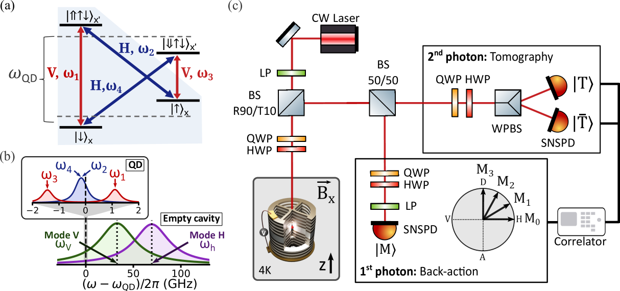
The device under study is a negatively-charged InGaAs QD emitting at 925 nm, embedded in an AlGaAs micropillar cavity [48] (see Methods). A transverse magnetic field (Voigt configuration), at , is applied perpendicularly to the pillar symmetry axis representing the direction. In Fig. 1a we display the QD energy levels, shifted by the Zeeman effect. The two electron spin states and form the ground states. The excited states are the two trion states and , consisting of a pair of electrons in a singlet configuration and a single hole, whose spin eigenstates are generally not oriented along the magnetic field axis [49].
The states are coupled to light with two orthogonal linear polarizations ( and respectively, with subscript used to label each transition energy ) [50]. In our experiment, we resonantly excite transition (), operating in a lambda configuration coupling the two ground states and to the excited state . Using a minimally invasive CW laser in the low-power regime (), to avoid optical spin pumping [51], allows maintaining a steady state close to the ground-state spin thermal equilibrium.
The optical properties of the micropillar cavity, extracted from polarization-dependent reflectivity measurements [52, 53] are illustrated in Fig. 1b. The fundamental cavity mode is slightly split into two orthogonal linear polarization modes. In the device under study, the cavity polarization eigenaxes match the optical transitions’ polarizations and in Fig 1a, as they are both determined by the internal strain field [49].
The measured cavity modes denoted as and have resonance energies and split by , and damping rates and . The effective top mirror output coupling for the ()-polarized mode is () [17]. The QD resonance frequency at 0T, , is red-detuned from the center cavity frequency by . This undesired detuning diminishes the device performance but remains small enough, compared to the cavity damping rates, to allow a significant coupling of the optical transitions to the cavity modes.
Analytical model of the back-action
Before detailing the experiments and the associated numerical simulations, we introduce a simple analytical model allowing to qualitatively interpret the results. Initially, i.e. before any photon has been detected, the spin is in a statistical mixture close to thermal equilibrium, defined by the state:
| (1) |
where refers to the spin density matrix and is the probability of finding the spin in the . From now on, we will ignore the label for the spin states. When an incoming photon, resonant with transition , interacts with the QD-cavity device, the resulting spin-scattered photon state can be written as:
| (2) |
where (resp. ) is the spin-scattered photon state obtained for a spin initially in state (resp. ):
| (3) |
The coefficients (with either or ) are reflection amplitudes associated to spin-preserving and frequency preserving transitions () or Raman spin-flip transitions (). The term describes the spin-scattered photon state obtained when the spin is initially in . In such a case, the QD remains unexcited by the CW laser which only allows exciting the transition. The reflection amplitude then corresponds to the empty cavity response, and we take (no Raman-spin flip transition from to ). Conversely, describes the spin-scattered photon state when the spin is initially in state . In this case, is governed by the interference between the directly-reflected light and the co-polarized Rayleigh scattered emission from the QD, both at frequency . The reflection amplitude results from the cross-polarized Raman emission at frequency leading to a spin-flip from to . The remaining terms relate to other scattering channels (such as transmitted, diffracted or lost light, or light spontaneously emitted outside the cavity modes) which we do not require to take into account in our experiment, as we post-select on the detection of a reflected photon.
We now consider the case where a scattered photon has been reflected and detected, thanks to a polarization analyzer, in the polarization state . For this work, we consider only linear polarization states, which we parametrize by the angle :
| (4) |
The detection of a reflected photon in polarization leads to a quantum back-action on the spin system, whose modified density matrix is described by , with components:
| (5) |
as well as and . In these expressions, represents the probability of actually detecting an -polarized reflected photon:
| (6) |
The case corresponds to the measurement of an -polarized photon, coming from a Raman spin-flip transition, with probability , projecting the spin in the state : this corresponds to populations and , with no coherence i.e. . The case corresponds to the measurement of a -polarized photon, with probability , which partially projects the spin such that with no coherence (). In both these situations, the back-action onto the spin state through the detection of a reflected photon acts only on the populations. To induce some coherence one needs to exploit the entanglement present in the state, through the measurement of a polarization state being in a superposition of and , i.e. . This is seen in Eq. (5), where the coherence term is both proportional to and to the product .
After the projective measurement, the conditional density matrix evolves towards the steady state (Eq. (1)) due to spin relaxation (affecting the populations and ) and decoherence (affecting the coherence ). One can track this dynamics by performing the polarization tomography of a second reflected photon, using measurements in three orthogonal bases (), at a time delay after the first photon is detected in polarization . This allows measuring the conditional Stokes parameters:
| (7) |
where is the probability of detecting a photon in the polarization state at a time delay conditioned to the detection of a first photon in polarization at . In particular, the conditional Stokes parameters , and are related to either the populations or the coherence of the spin state through:
| (8) |
with:
| (9) |
the total reflection probability for a second photon, conditioned to the detection of a first photon in polarisation . Such formulae show that the modified spin state is mapped to the polarization state of the next reflected photon. This mapping does not constitute a bijection, which would break the no-cloning theorem [47]. Still, it leads to a unique and direct correspondance between the spin density matrix and the reflected photon’s density matrix, governed by the three Stokes parameters in Eq. (8).
Through this model, one can qualitatively predict the expected evolution of the conditional Stokes parameters after the initial measurement back-action induced at by the detection of an -polarized photon. The parameters and should display damped oscillations in quadrature, as the non-diagonal coherence term evolves in phase at the Larmor frequency , and eventually decoheres with an effective rate . Conversely, should decay towards its stationary value at a rate , following the relaxation of the conditional populations towards and .
Polarization dynamics after spin projection
The optical setup for this experiment is schematized in Fig. 1c. The polarization of the input light, at frequency , is fixed with a linear polarizer (LP) and modified with a set of half- and quarter- waveplates (HWP/QWP) to excite only the cavity mode and, thus, the transition . The laser is focused into the micropillar cavity within a cryostat operating at 4K [17]. The reflected light is separated by a R90/T10 non-polarizing beam splitter (BS) and spatially filtered in a single mode fiber (not shown). A 50/50 free space BS divides the signal into two polarization analyzers.
The first polarization analyzer (bottom right) measures a first reflected photon in a given linear polarization state (see Eq. (4)) leading to a back-action on the spin state. For this experiment, we measure four different polarization states labeled as , , and described by , where corresponds to polarization and to the diagonal polarization . The second analyzer (top right) performs the polarization tomography of a second reflected photon, which we condition to the first through post-processing with a correlator, via time-resolved 2-photon correlations:
| (10) |
where is the conditional probability defined in Eq. (7) and the uncorrelated probability of detecting a -polarized photon.
We note that such a technique extends the approach experimentally pioneered in Ref. [54, 55]
, where pillar-based interfaces were used only as photon emitters and were studied only through cross-correlations, in orthogonal measurements bases, e.g. or . A key ingredient of our approach lies in the possibility to independently choose the polarization axis for the first detected photon, to control the measurement-induced back-action on the spin state (see Eq. (5)), and for the subsequent reflected photon after a delay , to probe the effect of this back-action through polarization tomography.
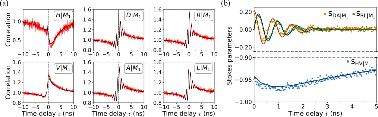
Fig. 2a shows the measured two-photon correlations with the first photon measured in polarization . In this figure, both for positive and negative delays, the experimental data are found to be in excellent agreement with numerical simulations discussed later on (see Supplemental Materials, hereafter denoted as Ref. [56], for complete model discussion). In the following, we focus on the correlations at positive delays which correspond to the previously-discussed situation, where the -polarized photon is detected before the -polarized one. Negative delays correspond to the complementary situation, in which the measurement of a -polarized photon is detected before the -polarized one.
When , no coherent oscillations are observed, as the detection of a or polarized photon is only sensitive to the spin population, and not to the spin coherence. Indeed, using our analytical model, one finds that and . Indeed, an -polarized reflected photon can only arise from the Raman spin-flip transition , meaning that the spin was in the state. Conversely, a -polarized reflected photon can be obtained from the resonant transition for spin , or from the directly reflected laser for spin . For delays longer than the spin relaxation time, the spin populations relax back to the stationary regime and, as a result, and relax back to the uncorrelated probabilities and . The antibunching feature in the correlation, i.e. the observation that at short positive delays, is thus a direct signature that (and ). In turn, this conditional spin population imbalance leads to the observed bunching in the correlation, i.e. at short positive delays [56].
When , the spin coherence induced by the -polarized detection (i.e. ) leads to damped oscillations of the reflected photon polarization, mapping the spin precession. Additional features are also present in all correlations, as the total conditional reflectivity , including both polarizations and , is also increased at short positive delays, and decreases back to the stationary value as spin relaxation occurs. We discuss this effect in more detail with additional data in the Supplemental Materials [56].
An important interest of the tomography approach is that all the effects are decoupled by focusing on the polarization state of the second photon, regardless of the total reflectivity . This is performed by extracting the conditional Stokes parameters as defined by Eq. (7) and shown in Fig. 2b. In this figure, the parameters and display damped oscillations, following the evolution of the Larmor spin precession around the applied magnetic field. In addition to the spin relaxation, the parameter presents a transient regime for leading to an increase which is not directly expected from our analytical model. This regime is associated to the time required for the reflection amplitudes to reach their stationary values under a CW drive. This transient regime also affects the conditional probabilities , and thus the two-photon correlations in Fig. 2a, for delays shorter than .
We complement these discussions with a quantitative analysis through the physical parameters extracted from a fully numerical model of the QD-cavity system [17, 34, 56]. This model allows reproducing all the experimental data discussed in this paper, including additional measurements displayed in Supplemental Materials [56]. It includes the light-matter coupling strength and the spontaneous emission rate outside the cavity mode , together with an homogeneous pure dephasing of the radiative transitions, . Together with the cavity parameters, the QD parameters , and determine the device optical response in polarisation, and thus the amount of measurement back-action induced by photon detection. In addition, the parameters and govern the radiative lifetime [56], which in turn governs the transient regime visible at short delays.
Our numerical simulations also include charge dynamics, as described by the charge escape time and the charge occupation probability [56]. Indeed the device operates in a co-tunneling regime between the QD and the nearby n-doped region [17], leading to frequent spin resets which determine the spin relaxation time, .
Finally, our simulations include the electron transverse Landé factor which governs the Larmor precession with period . We also take into accout the interaction between the electron and the Overhauser field [57] with coupling strength [56], which governs the inhomogeneous spin coherence time [56, 54].
Measurement-induced quantum back-action
Our numerical model, associated with the full tomography of the second photon’s polarization, enables us to determine the spin state and study the effect that the first photon detection has on the spin.
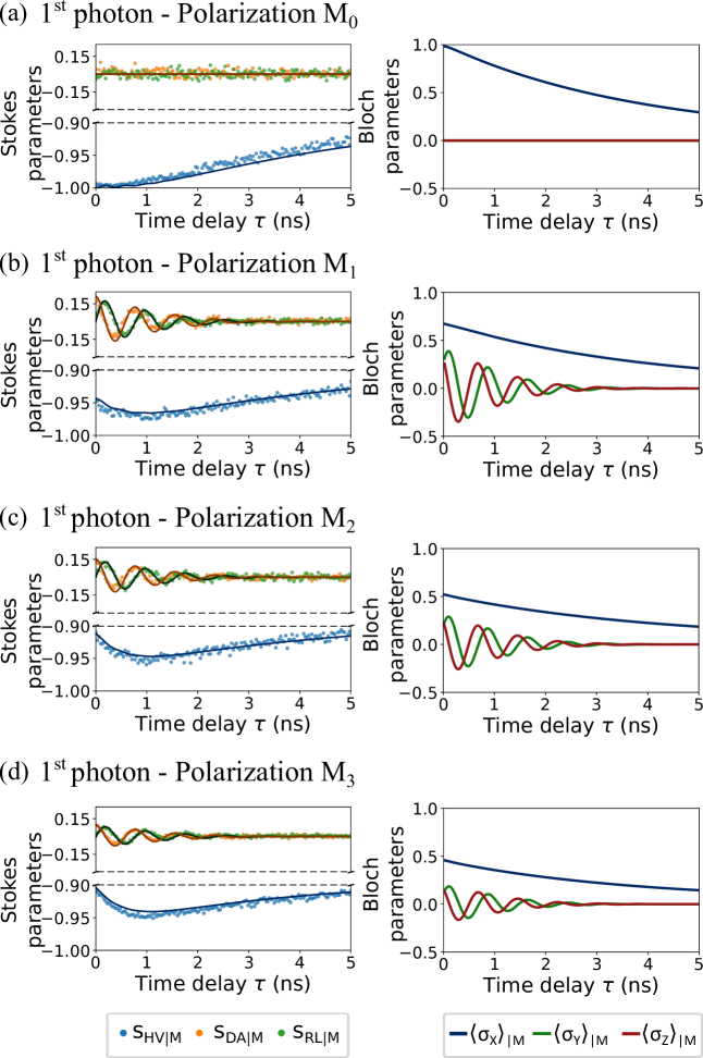
Fig. 3 displays both the measured reflected photon state (Stokes parameters , left panels) and the simulated conditional spin state (Bloch parameters with the spin Pauli matrix in the axis, right panels),
for the polarization states (a) , (b) , (c) and (d) . We note that the data in the left panel of Fig. 3b is the same as in Fig. 2b. When the first photon is measured on the polarization, the spin is projected into the eigenstate. In this situation, the back-action induced by the photon detection is classical, modifying the spin state populations with no induced coherence. By changing the polarization state , we project the spin in a partially coherent superposition of its energy eigenstates, that precesses around the magnetic field, as shown for , and .
The choice of polarization determines the amplitude of the oscillations of and , associated to the real and imaginary parts of , as expected from Eq. (5). This contrast variation is then transferred onto the second photon polarization (see Eq. (8)).
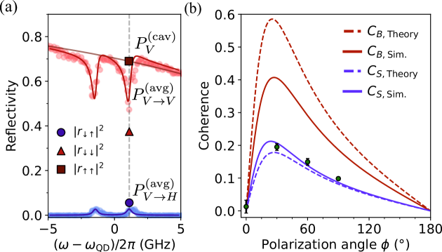
Finally, the experimental data and numerical simulations are compared with the analytical model. First, we infer from numerical simulations the occupation probabilities in the stationary regime : and , where the difference from 0.5 arises from the residual optical spin pumping induced by the excitation of the transition. Then, we extract the unconditional reflection probabilities in polarizations and , under polarized excitation, which we denote as and [17]. The results are displayed in Fig. 4a, together with their measured values, as a function of the detuning between the laser and the QD frequency at 0T. We infer the reflectivity coefficients and from the simulated values of the reflection probabilities at and of the populations and [56]. In addition, is directly taken as , the empty cavity reflectivity response in polarization . These reflection probabilities are also displayed in Fig. 4a for comparison with the average reflectivities.
We assess the amount of coherence induced onto the spin by the photon detection using the simulated values of , , , and in Eqs. (5) to (9). We define the Bloch (Stokes) coherence () as the amplitude of oscillations of and ( and ) at :
| (11) | ||||
| (12) |
as a function of the angle of the detected photon’s polarization state. Since the Bloch coherence can also be rewritten as , it provides a measurement of the off-diagonal elements of the spin density matrix after detection, and therefore quantifies the amount of spin coherence. The Stokes coherence is also proportional to the Bloch coherence as .
Fig. 4b shows the experimentally measured (red data points) as well as numerical simulations for both and (solid lines). As expected from our model, the coherences reach zero at and . In addition, based on the reflection amplitudes which govern , an optimal angle is obtained when is close to , i.e. close to polarization . Fig. 4b also displays the calculated coherences (dashed lines), using our analytical model, which qualitatively reproduces all these features. The discrepancy between the numerical and the analytical model comes from the latter not considering environmental noise sources (pure dephasing, hyperfine coupling, electron cotunneling) nor the transient regime associated to the finite radiative lifetime .
CONCLUSION
In this work, we have introduced a time-resolved tomography approach to measure the dynamics of a single spin state, mapped to the polarization state of a single reflected photon. Our results allow evidencing, quantifying and controlling the quantum back-action induced on the spin system through the detection of a single reflected photon. We introduced an analytical model qualitatively explaining the experimental data, allowing us to predict the conditional spin state after photon detection, and the conditional polarization state for a second reflected photon. We find that the spin dynamics, fully described by the conditional Bloch components , and , is in direct correspondence with the polarization dynamics of the second reflected photon, as described by the conditional Stokes coefficients , and . Therefore, with a single tomography measurement, one can extract all the timescales of the spin dynamics and quantify the back-action induced by the detection of a single reflected photon.
The observed results are in complete agreement with numerical simulations of the QD-cavity system [17, 34] which, contrary to the analytical model, take into account the environmental noise sources and the finite trion lifetime.
A first perspective for this work lies in the possibility to induce a maximally-coherent spin precession (, instead of here), ensuring that the conditional spin state is a pure state oscillating as . This is a prerequisite to ensure that a second photon, incoming at a specific time such as , becomes maximally entangled with the precessing spin [40, 41]. This will require operating in the pulsed regime, using devices with optimized Purcell enhancements (reducing the QD-cavity detuning) and increased spin coherence [54, 58]. This could allow producing one-dimensional photonic cluster states through the Lindner-Rudolf protocol [42], in a potentially deterministic way, using incoming/reflected photons instead of emitted ones. The final goal will be the use of spin-photon interfaces in quantum communication and quantum computing schemes exploiting a few nodes [59], and potentially a single node used both as emitter and receiver [60, 61, 62], to produce multidimensional photonic cluster states.
METHODS
Device fabrication
The QD-cavity device was grown by molecular beam epitaxy and consists of a -GaAs cavity, formed by two distributed Bragg reflectors, embedding an annealed InGaAs QD. The Bragg mirrors are made by alternating layers of GaAs and Al0.9Ga0.1As, with 20 (30) pairs for the top (bottom) mirror. To electrically contact the structure, the bottom mirror (Si-doped) presents a gradual doping from cm-3 down to cm-3. This level of doping is maintained in the first half of the cavity region and is stopped only 25 nm before the QD layer, which creates a tunnel barrier between the quantum dot and the Fermi sea. The top mirror is C-doped with increasing doping level, from zero to cm-3 at the surface. The micropillar is connected through four ridges to a large circular frame, attached to a gold-plated mesa enabling the electrical control. For full details on the device fabrication, see [48, 14].
ACKNOWLEDGEMENTS
This work was partially supported by the Paris Ile-de-France Région in the framework of DIM SIRTEQ, the Research and Innovation Programme QUDOT-TECH under the Marie Sklodowska-Curie grant agreement 861097, the European Union’s Horizon 2020 FET OPEN project QLUSTER (Grant ID 862035), the French National Research Agency (ANR) through project ANR-22-PETQ0013, a public grant as part of the ”Investissements d’Avenir” programme (Labex NanoSaclay, reference: ANR10LABX0035) and a government grant as part of France 2030 (QuanTEdu-France), under reference ANR-22-CMAS-0001. This work was done within the C2N micro nanotechnologies platforms and partly supported by the RENATECH network and the General Council of Essonne.
COMPETING INTERESTS
N.S. is a co-founder and P.S. is a scientific advisor and co-founder of the company Quandela. The other authors declare no competing interests.
References
- [1] Cirac, J. I., Zoller, P., Kimble, H. J. & Mabuchi, H. Quantum state transfer and entanglement distribution among distant nodes in a quantum network. Phys. Rev. Lett. 78, 3221–3224 (1997).
- [2] Kimble, H. J. The quantum internet. Nature 453, 1023–1030 (2008).
- [3] Reiserer, A. Colloquium: Cavity-enhanced quantum network nodes. Rev. Mod. Phys. 94, 041003 (2022).
- [4] Senellart, P., Solomon, G. & White, A. High-performance semiconductor quantum-dot single-photon sources. Nature Nanotechnology 12, 1026–1039 (2017).
- [5] Lu, C.-Y. & Pan, J.-W. Quantum-dot single-photon sources for the quantum internet. Nature Nanotechnology 16, 1294–1296 (2021).
- [6] Couteau, C. et al. Applications of single photons to quantum communication and computing. Nature Reviews Physics 5, 326–338 (2023).
- [7] Tiecke, T. G. et al. Nanophotonic quantum phase switch with a single atom. Nature 508, 241-244 (2014).
- [8] Volz, J., Scheucher, M., Junge, C. & Rauschenbeutel, A. Nonlinear phase shift for single fibre-guided photons interacting with a single resonator-enhanced atom. Nature Photonics 8, 965–970 (2014).
- [9] Bechler, O. et al. A passive photon-atom qubit swap operation. Nature Physics 14, 996-1000 (2018).
- [10] Daiss, S. et al. A quantum-logic gate between distant quantum-network modules. Science 371, 614–617 (2021).
- [11] Stolz, T. et al. Quantum-logic gate between two optical photons with an average efficiency above 40%. Phys. Rev. X 12, 021035 (2022).
- [12] Wang, Z. et al. An ultra-high gain single-photon transistor in the microwave regime. Nature Communications 13, 6104 (2022).
- [13] Reuer, K. et al. Realization of a universal quantum gate set for itinerant microwave photons. Phys. Rev. X 12, 011008 (2022).
- [14] De Santis, L. et al. A solid-state single-photon filter. Nature Nanotechnology 12, 663–667 (2017).
- [15] Le Jeannic, H. et al. Dynamical photon–photon interaction mediated by a quantum emitter. Nature Physics 18, 1191–1195 (2022).
- [16] Hansen, L. M. et al. Non-classical excitation of a solid-state quantum emitter (2024). arXiv:eprint 2407.20936.
- [17] Mehdi, E. et al. Giant optical polarisation rotations induced by a single quantum dot spin. Nature Communications 15, 598 (2024).
- [18] Bhaskar, M. K. et al. Experimental demonstration of memory-enhanced quantum communication. Nature 580, 60–64 (2020).
- [19] Pasini, M. et al. Nonlinear quantum photonics with a tin-vacancy center coupled to a one-dimensional diamond waveguide. Phys. Rev. Lett. 133, 023603 (2024).
- [20] Herrmann, Y. et al. Coherent coupling of a diamond tin-vacancy center to a tunable open microcavity. Phys. Rev. X 14, 041013 (2024).
- [21] Zhong, T., Kindem, J. M., Miyazono, E. & Faraon, A. Nanophotonic coherent light–matter interfaces based on rare-earth-doped crystals. Nature Communications 6, 8206 (2015).
- [22] Atatüre, M., Englund, D., Vamivakas, N., Lee, S. & Wrachtrup, J. Material platforms for spin-based photonic quantum technologies. Nature Reviews Materials 3, 38-51 (2018).
- [23] Awschalom, D. D., Hanson, R., Wrachtrup, J. & Zhou, B. B. Quantum technologies with optically interfaced solid-state spins. Nature Photonics 12, 516–527 (2018).
- [24] Coste, N. et al. High-rate entanglement between a semiconductor spin and indistinguishable photons. Nature Photonics 17, 582–587 (2023).
- [25] Borregaard, J., Sørensen, A. S. & Lodahl, P. Quantum networks with deterministic spin–photon interfaces. Advanced Quantum Technologies 2, 1800091 (2019).
- [26] Kim, H., Bose, R., Shen, T. C., Solomon, G. S. & Waks, E. A quantum logic gate between a solid-state quantum bit and a photon. Nature Photonics 7, 373-377 (2013).
- [27] Sun, S., Kim, H., Solomon, G. S. & Waks, E. A quantum phase switch between a single solid-state spin and a photon. Nature Nanotechnology 11, 539–544 (2016).
- [28] Sun, S., Kim, H., Luo, Z., Solomon, G. S. & Waks, E. A single-photon switch and transistor enabled by a solid-state quantum memory. Science 361, 57–60 (2018).
- [29] Chan, M. L. et al. On-chip spin-photon entanglement based on photon-scattering of a quantum dot. npj Quantum Information 9, 49 (2023).
- [30] Arnold, C. et al. Macroscopic rotation of photon polarization induced by a single spin. Nature Communications 6, 6236 (2015).
- [31] Wells, L. et al. Photon phase shift at the few-photon level and optical switching by a quantum dot in a microcavity. Phys. Rev. Appl. 11, 061001 (2019).
- [32] Androvitsaneas, P. et al. Efficient quantum photonic phase shift in a low q-factor regime. ACS Photonics 6, 429–435 (2019).
- [33] Androvitsaneas, P. et al. Quantum modulation of a coherent state with a single electron spin. Phys. Rev. Res. 6, 023276 (2024).
- [34] Gundín, M. et al. Spin noise spectroscopy of a single spin using single detected photons. Phys. Rev. Lett. 134, 036902 (2025).
- [35] Nguyen, C. T. et al. Quantum network nodes based on diamond qubits with an efficient nanophotonic interface. Phys. Rev. Lett. 123, 183602 (2019).
- [36] Stas, P.-J. et al. Robust multi-qubit quantum network node with integrated error detection. Science 378, 557–560 (2022).
- [37] Knaut, C. M. et al. Entanglement of nanophotonic quantum memory nodes in a telecom network. Nature 629, 573–578 (2024).
- [38] Parker, R. A. et al. A diamond nanophotonic interface with an optically accessible deterministic electronuclear spin register. Nature Photonics 18, 156–161 (2024).
- [39] Leuenberger, M. N. Fault-tolerant quantum computing with coded spins using the conditional faraday rotation in quantum dots. Phys. Rev. B 73, 075312 (2006).
- [40] Hu, C. Y., Young, A., O’Brien, J. L., Munro, W. J. & Rarity, J. G. Giant optical faraday rotation induced by a single-electron spin in a quantum dot: Applications to entangling remote spins via a single photon. Phys. Rev. B 78, 085307 (2008).
- [41] Hu, C. Y., Munro, W. J. & Rarity, J. G. Deterministic photon entangler using a charged quantum dot inside a microcavity. Phys. Rev. B 78, 125318 (2008).
- [42] Lindner, N. H. & Rudolph, T. Proposal for pulsed on-demand sources of photonic cluster state strings. Phys. Rev. Lett. 103, 113602 (2009).
- [43] Koshino, K., Ishizaka, S. & Nakamura, Y. Deterministic photon-photon gate using a system. Phys. Rev. A 82, 010301 (2010).
- [44] Maffei, M. et al. Energy-efficient quantum non-demolition measurement with a spin-photon interface. Quantum 7, 1099 (2023).
- [45] Huet, H. et al. Deterministic and reconfigurable graph state generation with a single solid-state quantum emitter (2025). arXiv:eprint 2410.23518.
- [46] Smirnov, D. S., Reznychenko, B., Auffèves, A. & Lanco, L. Measurement back action and spin noise spectroscopy in a charged cavity qed device in the strong coupling regime. Phys. Rev. B. 96, 165308 (2017).
- [47] Wootters, W. K. & Zurek, W. H. A single quantum cannot be cloned. Nature 299, 802–803 (1982).
- [48] Somaschi, N. et al. Near-optimal single-photon sources in the solid state. Nature Photonics 10, 340–345 (2016).
- [49] Ramesh, P. R. et al. The impact of hole -factor anisotropy on spin-photon entanglement generation with InGaAs quantum dots (2025). arXiv:eprint 2502.07627.
- [50] Warburton, R. Single spins in self-assembled quantum dots. Nature Materials 12, 483-493 (2013).
- [51] Xu, X. et al. Fast spin state initialization in a singly charged InAs-GaAs quantum dot by optical cooling. Phys. Rev. Lett. 99, 097401 (2007).
- [52] Antón, C. et al. Tomography of the optical polarization rotation induced by a single quantum dot in a cavity. Optica 4, 1326–1332 (2017).
- [53] Hilaire, P. et al. Accurate measurement of a 96% input coupling into a cavity using polarization tomography. Appl. Phys. Lett. 112, 201101 (2018).
- [54] Coste, N. et al. Probing the dynamics and coherence of a semiconductor hole spin via acoustic phonon-assisted excitation. Quantum Science and Technology 8, 025021 (2023).
- [55] Serov, Y. et al. Hidden anisotropy controls spin-photon entanglement in a charged quantum dot (2024). arXiv:eprint 2410.02562.
- [56] See Supplemental Materials for additionnal information about the experimental setup and a detailed discussion of the numerical simulations.
- [57] Urbaszek, B. et al. Nuclear spin physics in quantum dots: An optical investigation. Rev. Mod. Phys. 85, 79–133 (2013).
- [58] Hogg, M. et al. Fast optical control of a coherent hole spin in a microcavity (2024). arXiv:eprint 2407.18876.
- [59] Borregaard, J. et al. One-way quantum repeater based on near-deterministic photon-emitter interfaces. Phys. Rev. X 10, 021071 (2020).
- [60] Pichler, H., Choi, S., Zoller, P. & Lukin, M. D. Universal photonic quantum computation via time-delayed feedback. Proceedings of the National Academy of Sciences 114, 11362–11367 (2017).
- [61] Zhan, Y. & Sun, S. Deterministic generation of loss-tolerant photonic cluster states with a single quantum emitter. Phys. Rev. Lett. 125, 223601 (2020).
- [62] Ferreira, V. S. et al. Deterministic generation of multidimensional photonic cluster states with a single quantum emitter. Nature Physics 20, 865–870 (2024).