Magnetoelectric training of multiferroic domains in Mn2GeO4
Abstract
We study the trilinear magnetoelectric coupling between ferroelectric, ferromagnetic, and antiferromagnetic domains in the spin-spiral multiferroic Mn2GeO4, imaging the evolution of domains under both magnetic and electric fields via optical second harmonic generation. Once activated, this trilinear coupling enables the highly repeatable inversion of an inhomogeneous ferroelectric domain pattern upon global reversal of the magnetization. We specifically consider the initial domain evolution from zero-field cooling and find that polarization and magnetization domains form independently when entering the multiferroic phase. From here, a field training process is required to obtain the domain inversion mentioned above. We explain this training behavior of the complex magnetoelectric coupling as a pathway from metastable to equilibrium domain patterns, a process relevant to understanding the magnetoelectric behavior in other multiferroic materials with highly interlinked coexisting order parameters.
Magnetoelectric engineering, such as electric-field-induced switching of a magnetic moment, underlies much of the recent research on multiferroics, that is, on materials with coexisting magnetic and ferroelectric order within the same phase [1, 2, 3, 4, 5]. The coexistence of multiple order parameters can facilitate pronounced magnetoelectric cross-coupling [6, 7]. Especially strong magnetoelectric effects are observed in antiferromagnetic spin-spiral multiferroics, in which the inversion-symmetry-breaking compensated spin order is directly responsible for the emergence of a spontaneous electric polarization [8, 9, 10].
On the mesoscopic scale, the magnetoelectric coupling between the magnetic and ferroelectric domains influences the spatial domain configuration of one order parameter even under application of a field conjugated to another order parameter [11, 12, 13]. A particular case of such magnetoelectric domain cross-control has been demonstrated in conical-spiral multiferroic Mn2GeO4 [14, 15, 16, 17], where a trilinear magnetoelectric coupling of order-parameter terms enables the complete inversion of a ferroelectric multi-domain pattern by a homogeneous magnetic field [18]. Specifically, the spontaneous polarization is reversed in every position on the sample, while the domain pattern as such remains unchanged.
In this work, we further scrutinize the trilinear magnetoelectric coupling in Mn2GeO4 using optical second harmonic generation (SHG) as spatially resolving domain-imaging technique. Whereas previous work focused solely on the behavior of field-poled equilibrium domain states, here we focus on the spontaneous formation of ferroelectric and ferromagnetic domains and their initial field-driven evolution.
We find that upon zero-field cooling into the multiferroic phase of Mn2GeO4, ferroelectric and ferromagnetic domains form independently. A field training cycle is required to establish the rigid three-order parameter coupling and domain inversion mentioned above [18]. Our findings emphasize the importance of a comprehensive understanding of the domain evolution away from equilibrium for obtaining fully reproducible magnetoelectric control, a prerequisite for future multiferroic devices.
I Ferroic Properties of Mn2GeO4
The olivine compound Mn2GeO4 crystallizes in the orthorhombic space group Pnma with principal axes [19]. Its optical and magnetic properties are closely linked to the electronic configuration of the Mn2+ ions [20], which occupy two crystallographic sites with octahedral coordination. The Mn1 ions occupy centrosymmetric positions, while the Mn2 ions are situated in acentric positions, but with local mirror symmetry [19].
Mn2GeO4 exhibits a series of magnetic phase transitions [14, 15, 16, 17]. In the current work, we focus on the conical spin-spiral phase, which is entered through a first-order phase transition at about [15, 14, 21]. The conical spin-spiral order in this low-temperature multiferroic phase is characterized by the coexistence of a multitude of order parameters associated with the commensurate wave vector and the incommensurate wave vectors and [15, 14]. Associated with the commensurate order parameterized by are the antiferromagnetic order parameters and . Here, is purely antiferromagnetic, while is related to a small canted magnetization with magnitude . The incommensurate modulation associated with describes a cycloidally modulated spin structure and induces a spontaneous “improper” electric polarization with magnitude . The macroscopic magnetization and polarization can be switched by magnetic fields () or electric fields () [14, 17].
In the multiferroic phase below , the spontaneous magnetization and polarization are strongly coupled. This has been demonstrated by the synchronous reversal of both magnetization and polarization in a magnetic field for a single-–single- domain configuration [14, 17] as well as by the magnetic-field-driven inversion of a multi-–single- domain pattern. In the latter case, the spatial distribution of the ferroelectric domains is retained while the local polarization is flipped [18]. Macroscopically, the domain inversion has been attributed to a trilinear magnetoelectric coupling term [22, 18]. Microscopically, the simultaneous switching of polarization and magnetization in Mn2GeO4 originates from a magnetic-field-induced directional flop of the Mn spin-spiral cone axis, which reverses both the net magnetization and the projected spiral circulation, and thus the spin-induced polarization [17].
II Methods
Single crystals of Mn2GeO4 were grown by the floating-zone method [23], oriented by Laue diffraction, and cut into platelets with faces perpendicular to the crystallographic or axes. The samples were lapped and polished from both sides with silica slurry (Eminess Ultrasol 555). The final thickness was approximately (-cut) and (-cut).
Linear optical absorption spectra were measured at room temperature, using a microspectrometer (JASCO MSV-370). SHG experiments were performed with amplified laser pulses of variable photon energy in a transmission geometry, using a setup described elsewhere [24]. The spatial distribution of the ferroelectric domains was imaged with a telephotography lens (Soligor 135 mm, 1:3.5) using a liquid-nitrogen-cooled CCD camera as the detector (Photometrics CH270). All imaging experiments were performed in the multiferroic phase at , with the low-temperature sample environment provided by a liquid-helium-operated magnetic-field cryostat (Oxford Spectromag 4000).
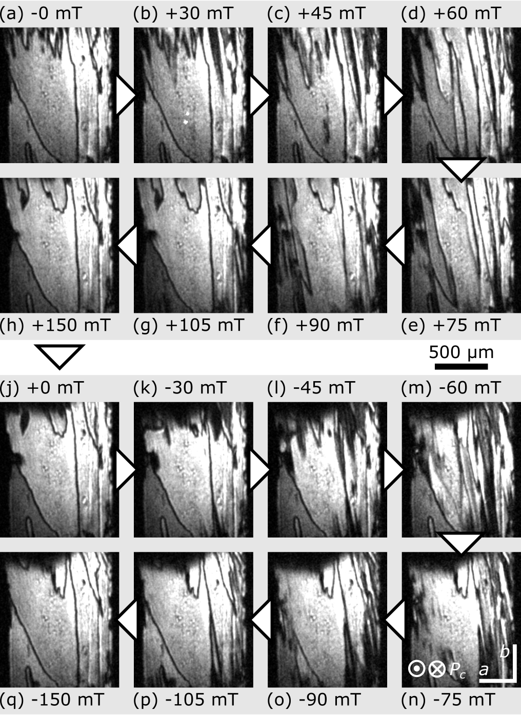
To switch the spontaneous magnetization of Mn2GeO4, magnetic fields were applied along the crystallographic direction. To be able to observe the SHG signal of the -cut platelet, the sample had to be rotated by approximately around the vertical direction. This rotation leads to a perspective distortion of the SHG images. This is corrected by stretching the images in Fig. 2 and Fig. 5 along their horizontal direction.
To obtain electric-field poling within the multiferroic phase in the -cut sample, transparent ITO electrodes were sputtered onto both sides of the polished crystal, which allowed us to apply of fields up to .
III Optical characterization
| 1393 | 1146 | 2310 | background | |||
| #0 | – | – | 1.760 | |||
| – | – | 0.205 | ||||
| – | – | 271 | ||||
| #1 | 2.172 | 2.177 | 2.103 | |||
| 0.398 | 0.474 | 0.339 | ||||
| 1090 | 1017 | 2025 | ||||
| #2 | 2.784 | 2.672 | 2.755 | |||
| 0.690 | 0.576 | 0.815 | ||||
| 4360 | 2406 | 7955 | ||||
| #3 | 2.990 | 3.000 | 2.990 | |||
| 0.116 | 0.122 | 0.118 | ||||
| 681 | 621 | 948 | ||||
| #3′ | 3.090 | – | 3.106 | () | ||
| 0.163 | – | 0.129 | ||||
| 264 | – | 201 | ||||
| #4′ | – | 3.262 | – | |||
| – | (0.850) | – | ||||
| – | (6160) | – | ||||
| #4 | 3.375 | 3.387 | 3.419 | |||
| 0.357 | (0.080) | 0.380 | ||||
| 1843 | (101) | 2159 | ||||
| CT | 3.716 | 3.638 | 3.861 | charge transfer | ||
| 0.482 | 0.432 | 0.626 | ||||
| 77364 | 49271 | 102906 | ||||
| 8821 | 10623 | 11069 |
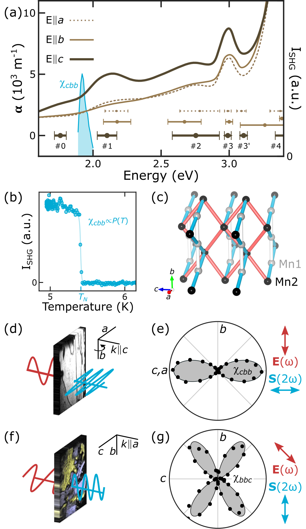
Due to the electronic configuration of the Mn2+ ions, optical - transitions are parity-forbidden in Mn2GeO4 [25]. Mn2GeO4 crystals appear reddish-brown, however, due to the low-energy tail of the lowest-lying MnO charge-transfer excitation peaking around . The polarization-dependent linear spectra in Fig. 1(a) show the strongest absorption for light polarized along the crystallographic direction, leading to a pronounced dichroism. Each spectrum was fitted with a multi-Gauss function to extract the central energies and the full-width-half-maximum peak widths of the crystal-field transitions #1 to #4. The transitions are indicated in Fig. 1(a) and are listed in Tab. 1 [25, 26, 20]. The peak labeled #0 at was found in the -polarized spectrum only and is not related to a crystal-field transition; its origin is discussed below.
To spatially resolve domains and to image the effect of field-driven ferroic switching and magnetoelectric coupling in Mn2GeO4, we employ optical SHG, which describes the emission of light at frequency from a material irradiated with laser light at frequency , as described by the equation
| (1) |
Here, the electric-field components of the incident light field, , induce a source term for the emitted frequency-doubled light wave. The tensor components of the non-linear susceptibility depend on the point-group symmetry of the host material and vanish in leading order for materials with inversion symmetry [27, 28]. Therefore, SHG is especially suitable for investigating ferroelectrics and spin-spiral multiferroics [29, 30], where spontaneous polarization arises as an inversion-symmetry-breaking order parameter.
In Mn2GeO4, a background-free SHG signal appears with a jump below , Fig. 1(b), showing a similar temperature dependence as the spontaneous polarization [14]. In addition, we find an electric-field-induced SHG (EFISH) contribution with an amplitude proportional to the strength of the applied external field and independent of the sample temperature. The spontaneous SHG signal and the EFISH contribution with exhibit the same spectral dependence, peaking for photon energies around , as shown by the blue peak in Fig. 1(a).
In agreement with symmetry selection rules [28], the SHG response of a -cut Mn2GeO4-sample originates from the component , Fig. 1(e), while for the -cut sample is observed; see Fig. 1(g). For both and , the polarization of the source term has components parallel to the Mn1-O-Mn2 bonds forming zigzag chains running along the direction [marked blue in Fig. 1(c)], and is parallel to the Mn2-O-Mn2 bonds promoting strong antiferromagnetic exchange and linking neighboring zigzag chains [red in Fig. 1(c)] [31, 15, 14, 21]. This particular polarization dependence and the spectral vicinity of the SHG peak to the absorption peak #0 could indicate that both linear and nonlinear responses might be linked to pairwise spin-flip transitions enhanced by exchange interactions between neighboring Mn2+ ions [32].
An intrinsic zero-field SHG contribution is present in the multiferroic phase of Mn2GeO4 only and is sensitive to the spontaneous polarization. Therefore, they can be used for the background-free observation of the ferroelectric multi-domain pattern with a spatial resolution down to about . In general, neighboring domains appear in SHG images with constant brightness , separated by dark lines that mark the position of the ferroelectric domain walls. These lines are caused by local destructive interference between SHG contributions from neighboring domains due to the phase shift () associated with these. For the -cut sample, interference with a reference EFISH signal was used to generate a domain contrast, with domains highlighted in yellow and blue, respectively.
IV Magnetoelectric domain interconversion
As shown in previous work [14, 17], repeated application of a magnetic field along not only switches the magnetization of Mn2GeO4 but simultaneously reverses the improper polarization. This effect leads to inversion of the ferroelectric domain pattern with one integral magnetic field sweep. Locally, each polarization state is inverted, , while the position of the ferroelectric domain walls as such is left unchanged [18].
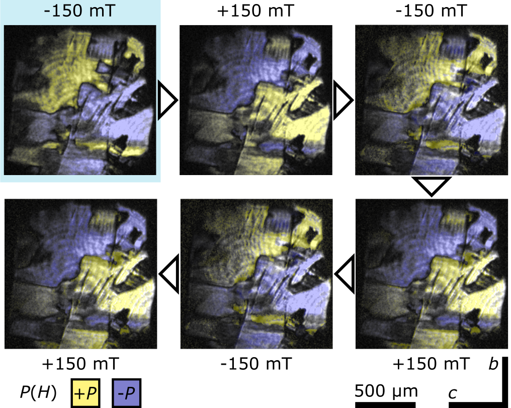
The magnetoelectric domain interconversion, which results in the transition of a multi-()–single-() domain pattern to its inverted multi-()–single-() state, is demonstrated for a -cut Mn2GeO4 sample in Figs. 2(a,h) and 2(j,q). Note how the final domain pattern in panel (q) still resembles that of the initial pattern in panel (a). Minor deviations occur only towards the edges of the image where the sample is mounted, which points to the disruptive influence of sample strain. The magnetoelectric inversion of the domain pattern is highly repeatable, as shown for five subsequent magnetic field reversals in Fig. 3.
Regardless of the repeatable interconversion, in intermediate fields [Figs. 2(b-f,k-p)], additional needle-like domains appear at the top of the sample and grow downward. As the spatial distribution and temporal evolution of domains in this transient multi-()–multi-() configuration is different in each poling cycle, the recovery of the initial domain state cannot be attributed to local pinning centers or other memory effects, and instead is governed by the intrinsic global magnetoelectric coupling.
To discuss the underlying cross-coupling effects, two switching mechanisms need to be distinguished in Mn2GeO4. These are represented by bilinear and trilinear coupling terms as contributions to the free energy, which must be minimized in equilibrium. First, the bilinear coupling terms describe how the applied fields act directly on the conjugated order parameter, that is, magnetization and polarization , via
| (2) |
Second, the magnetoelectric trilinear coupling term is associated with the response of non-conjugated macroscopic order parameters according to [17, 22, 18]:
| (3) |
Due to the compensated spin order, the antiferromagnetic domains associated with the parameter (or, more precisely, a combination of commensurate and incommensurate order parameters, see [17, 18]) are robust against moderate electric and magnetic fields. As a consequence of the stability of , when is switched through via the bilinear contribution in Eq. (2), needs to reverse simultaneously in order to satisfy minimization of the trilinear free-energy contribution in Eq. (3). In contrast, if is switched by an electric field , the magnetization must reverse at the same time.
IV.1 Magnetoelectric training of ferroic domains
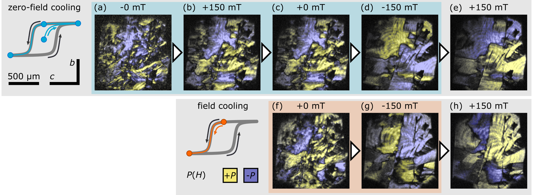
So far, we discussed the magnetoelectric behavior under equilibrium conditions. However, as we show, the initial magnetic-field-driven evolution of a multi-–multi- domain pattern obtained after zero-field cooling is different from the interconversion effect described above.
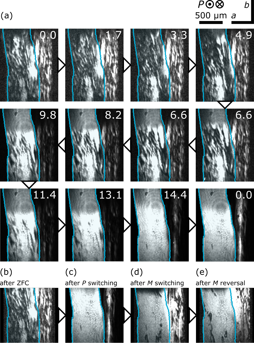
Upon zero-field cooling to the multiferroic phase, that is, and , polarization () and magnetization () domains form independently. This is demonstrated in Fig. 4(a-c): Here, the initial multi-–multi- domain pattern, Fig. 4(a), shows small domains with predominantly diagonally oriented boundaries. An applied magnetic field converts the initial state to a multi-–single- domain pattern. Due to the magnetoelectric coupling parameterized by Eq. (3), the ferroelectric domain pattern is expected to change in the regions where the magnetization has been switched. Indeed, as shown in Fig. 4(b,c), after -field poling, the domains appear larger, with boundaries preferably aligned with the horizontal (polar) axis, and slightly inclined to the vertical direction. The magnetic-field-driven change in the domain pattern hence confirms the original independence in the distribution of the ferroelectric and ferromagnetic domains after entering the multiferroic phase.
A training procedure is required to obtain the repeatable global magnetoelectric domain interconversion of steady-state poling. To describe this training procedure, we need to distinguish the effect of domain poling, that is, the transformation of the virgin multi-domain pattern obtained after zero-field cooling into a single-domain configuration, and domain switching, describing the inversion of a single-domain pattern via an intermittent multi-domain state as described in Fig. 2. In other words, poling affects only a subset of domains, whereas switching inverts all the domains in the applied field.
The image sequence shown in Fig. 4(a-c) represents the initial domain poling toward a single-() domain configuration. Upon the first global switching of the magnetization , Fig. 4(c,d), the majority of domains invert to ; however, this step is still distinct from the rigid and repeatable interconversion discussed above. In particular, some domains (especially smaller ones) disappear and the domain walls straighten considerably. Consequently, the resulting multi-()–single-() domain pattern is different from the previous multi-()–single-() domain pattern, in contrast to what would naïvely be expected from the magnetoelectric coupling term in Eq. (3).
A similar training behavior is observed even if the sample has been initially cooled in a moderate magnetic field of , as shown in Fig. 4(f,g). Only subsequent reversals reveal the magnetic-field-driven equilibrium inversion of the ferroelectric domain pattern, Fig. 4(d,e) and Fig. 4(g,h).
The observed changes indicate that the relationship between the domains of , , and is not yet in equilibrium after zero-field cooling or with a moderate bias field applied. Obtaining the equilibrium state of field-induced domain inversion requires a magnetic-field training cycle, as illustrated by the blue and orange paths on the hysteresis loops in Fig. 4. After this initial step, the system globally minimizes the magnetoelectric coupling term in Eq. (3) and allows for repeated domain inversion in switching cycles.
IV.2 Electric-field control of multiferroic domains
Now we turn toward direct control of the ferroelectric domains by the conjugate electric field. After zero-field cooling, the -cut sample obtains a multi-–multi- domain pattern, Fig. 5(a,b). Here, domains with opposite polarity form stripes with a typical width of along the crystallographic direction. As shown in Fig. 5(a), application of an electric field leads to the growth of a region with uniform brightness associated with a single polarization domain.
Approximately are required to initiate domain growth, giving a lower bound for the coercive field to orient the ferroelectric domains. Saturation is achieved for fields of about , and the resulting single- domain configuration is retained after the applied electric field is removed; see Fig. 5(c). Thus, application of an electric field converts a multi-–multi- domain pattern, shown in Fig. 5(b), to a single-–multi- domain pattern, shown in Fig. 5(c).
In addition to acting on the polarization , due to the magnetoelectric cross-coupling term in Eq. (3), the electric field also acts on the magnetization domains of Mn2GeO4Ṡtarting from the electric-field-poled single-–multiple- state, subsequent magnetic-field poling and magnetization reversal lead to a multi-–single- domain pattern. This is demonstrated by the reappearance of black domain walls in the SHG images in Fig. 5(d,e).
If we were to assume that the magnetoelectric coupling term in Eq. (3) were globally minimized after zero-field cooling, the final ferroelectric domain pattern after electric- and magnetic-field poling should correspond to the product of the initially largely independent and domain distributions. In this case, the typical observed domain size should be similar to the smaller size of the initial or domains. The prediction of smaller domains contradicts our experimental observations, where after magnetoelectric training, Fig. 5(d,e), the ferroelectric domains are larger than after zero-field cooling, Fig. 5(b).
This observation of apparent domain size evolution further corroborates the earlier conclusion that zero-field cooling into the multiferroic state of Mn2GeO4 results in a metastable domain configuration. In this initial state, the order parameters , , and do not yet conform globally to the energy minimization dictated by the trilinear magnetoelectric coupling term in Eq. (3). In general, it appears that the training cycle leads to the formation of larger domains with predominantly straight domain walls, showing a tendency to minimize the total length of the energy-wise costly domain boundaries.
V Model for the training behavior in domain evolution
We now propose both a phenomenological and a microscopic model to rationalize the magnetoelectric training of the multiferroic domain patterns in Mn2GeO4.
The phenomoneological model is based on two key experimental observations: First, ferroelectric polarization and ferromagnetic magnetization form different domain patterns upon entering the multiferroic phase. Second, upon zero-field cooling, or cooling with only moderate fields applied, the system adopts a metastable configuration where the trilinear magnetoelectric coupling term in Eq. (3) is not yet fully minimized.
The initial formation of largely independent domains in , , and is facilitated by the first-order multiferroic transition in Mn2GeO4, which leads to the spontaneous emergence of associated magnetic and electric moments below . Consequently, it is unlikely that higher-order terms in the free energy, such as the in Eq. (3), are globally minimized when cooling to zero field. This is in contrast to a second-order phase transition, where the continuous emergence of order enables the formation of an equilibrium multi-order-parameter domain pattern minimising all terms in the free energy simultaneously.
The formation of a metastable non-equilibrium multiferroic domain pattern then requires a deterministic two-step field poling protocol with subsequent global field switching to enable global and highly repeatable magnetoelectric domain inversion [14, 17, 18].
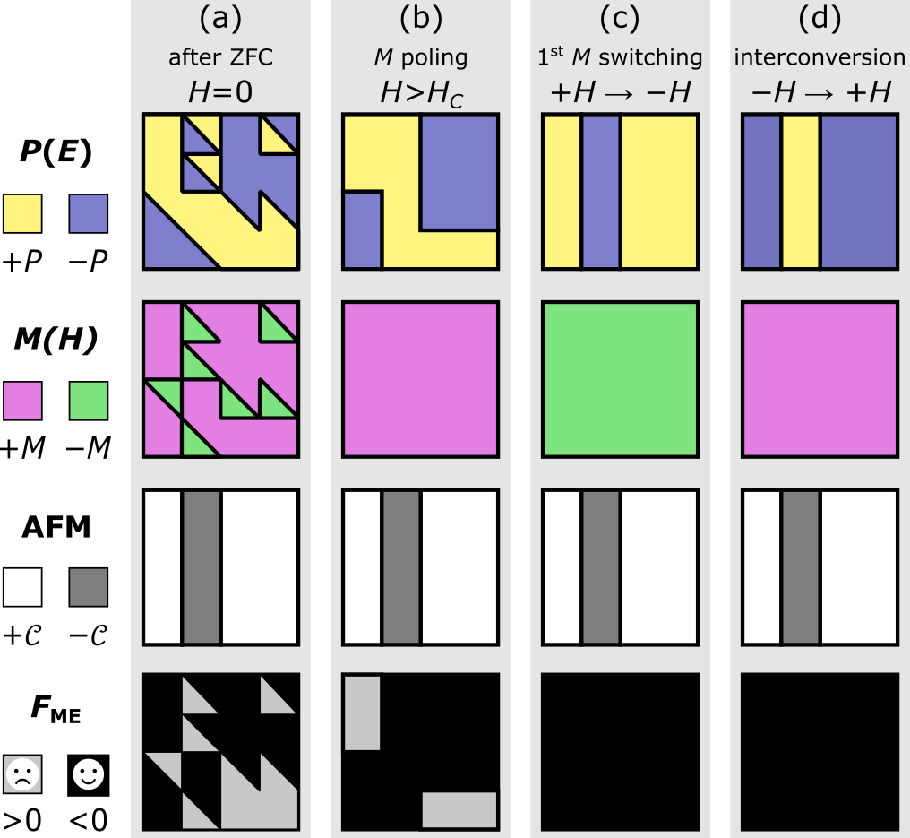
The effect of the magnetoelectric training steps on the mesoscale domain distributions are illustrated in Fig. 6, where pictograms show domain distributions of experimentally accessible polarization (yellow/blue), magnetization (pink/green), and antiferromagnetic order parameter (white/gray), as well as the local sign of the trilinear magnetoelectric coupling term (gray/black). In regions where , as highlighted in gray, the system is not in a local equilibrium with respect to the magnetoelectric coupling term.
In the first training step, Fig. 6(b), application of a magnetic field poles the multi-–multi- domain pattern to a multi-–single- state. At the same time, the system will try to minimize , which can happen in two ways: First, if is already in place, both and will switch simultaneously. Second, if only the magnetic-field-driven order parameter will switch so that . As a result, the pattern of the domain observed after poling is not a simple product between the initial and domains, and the change in domain morphology (that is, shape and size) is apparent, as was observed in our experiments.
In the second training step, Fig. 6(c), we need to reverse the magnetization of all the regions that had not reoriented under the magnetic poling field in the first step. This gives the associated domains the opportunity to reverse or not toward the state of minimum energy, just as in the first step. Hence, by globally switching the magnetization from a single- to a single- state, the system can adopt a configuration that globally minimizes , imprinting the domain pattern of antiferromagnetic order onto the order.
After these initial field steps, the system has adopted a domain configuration that leads to a global minimization of (highlighted in black). Subsequent switching of the magnetization, Fig. 6(d), then leads to repeatable magnetoelectric inversion of the ferroelectric multi-domain pattern in agreement with previously published results [15, 17, 18].
For the case that all possible domain states characterized by the combination of , and form with equal probability upon entering the multiferroic phase 111Even though the transition into the multiferroic state is of first order, depending on the cooling rate across some cross-coupling might already come in effect, which may result in a non-even balance of the theoretically possible 16 domains formed by combinations of , and ., a specific sequence of the observed switched domain fraction can be predicted. The first poling reverses 50% of the domains, and for 50% of these, follows, which equals a total of 25%. The subsequent field switch reverses all domains from the first poling and half of the remaining domains, leading to a total of 75%. This completes the training, and henceforth, all domains (100%) switch repeatedly with every magnetic-field reversal, as shown in Fig. 3. Although a trend for such behavior is seen in Fig. 4, a more quantitative analysis is prohibited by the small size of our sample in relation to the extension of the domains and the high density of crystal defects.
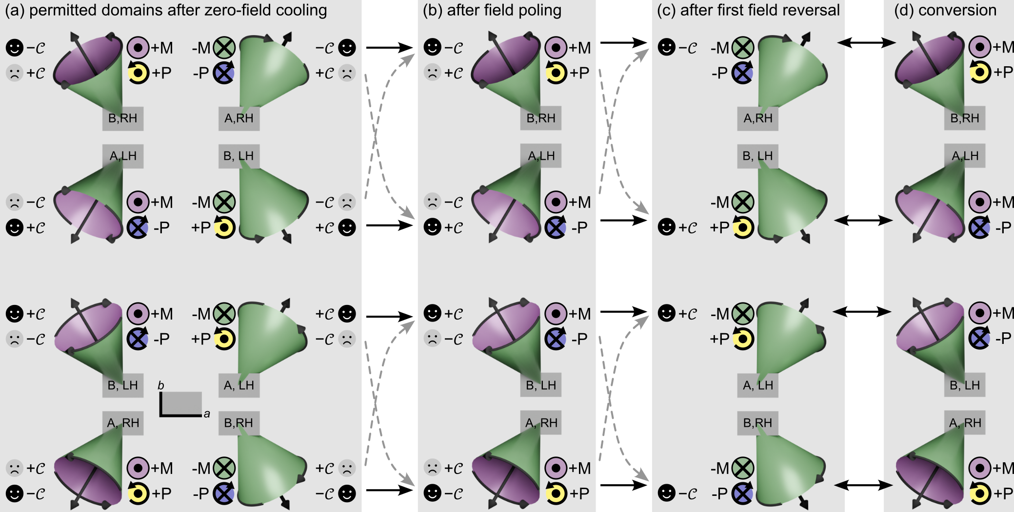
On a microscopic level, the steps of the training procedure are schemically represented in Fig. 7. Here, a representative cone of the conical Mn spin spiral is shown, with the orientation of the axis determining the sign of the magnetization (green/pink) and the projected circulation around the cone determining the sign of the polarization (black arrows, green/blue). In equilibrium, each of the incommensurate domains characterized by or (just “A” and “B” in Fig. 7) can exist in a left- or right-handed chirality, determined by the sign of [17] [Fig. 7(c,d)].
After zero-field cooling across the first-order transition, domains of any of the sign combinations of , , and can form. Since we have two possible conical orientations for each of these sign combinations, we arrive at a total of 16 possible domain states. Eight of these states are schematically represented in Fig. 7(a), and the remaining factor of two results from the choice of or for each of these, as indicated by icons to the left or right. If the relative sign of is opposite to the sign of (indicated with ☺), we have a ground-state configuration, where Eq. (3) is minimized. A switching field then leads to a reversible rotation of the cone axis, inverting both and simultaneously, as well as interchanging the and domains, while leaving the chirality (and therefore ) unchanged (solid black arrows).
In contrast, if , the domain state is energetically unfavorable (indicated with ☹), and a likely irreverisble transformation under applied fields is a reorientation of the cone axis via a “cone flop” (similar to an umbrella flipping over). This reverses , but leaves the translation vector, or , as well as the polarity (i.e., projected circulation) unchanged. As this operation changes the sign of only, the trilinear energy term is then minimized. Any energetically unfavorable domain can then be successively eliminated by the training procedure discussed above.
VI Discussion
The effect of transient evolution of multiferroic domains in Mn2GeO4 has not been resolved earlier in integrated pyroelectric current and neutron scattering experiments, as these required single-–single- domain patterns to obtain meaningful results [15, 14, 17]. Furthermore, the combined cooling fields applied in these earlier experiments [17], that is, and (and therefore ), are at least one order of magnitude larger than the moderate fields used for the SHG domain imaging experiments in this work, that is, and (respectively, ). To create a well-defined single-–single--single- domain pattern in Mn2GeO4 via field cooling across the first-order multiferroic transition, in which even the antiferromagnetic order parameter is set globally, a minimum combined field strength between those values is therefore required.
An interesting observation that might point to the influence of the non-equilibrium domain configuration on macroscopic measurements even after field cooling has been presented in [34], where the authors report an irreversible polarization increase by 15% upon the first application of a field.
VII Conclusions
In this work, we considered the initial evolution and interplay of the ferroelectric and ferromagnetic domains in multiferroic Mn2GeO4 after zero-field cooling, as observed via optical second harmonic generation. Our results demonstrate that a training procedure is necessary to obtain reliable and repeatable magnetoelectric switching of the multiferroic domain configuration. The procedure is governed by the trilinear coupling of magnetic and electric order parameters, which is initially not energy-minimized, and thus leads to irreversible changes in the domain morphology. The clarification of this training behavior is of interest for potential applications that rely on strong and reversible cross-correlations between coexisting order parameters for deterministic control. This cross-correlation needs to be robust against disruptive effects such as strain or stray fields.
While demonstrated here for the example of Mn2GeO4, we expect that similar training procedures are relevant for other multiferroics with first-order transitions, or which have been quenched through a second-order transition, and therefore feature initial non-equilibrium multi-order-parameter domain configurations. Similar effects could, for example, occur in materials such as spinel CoCr2O4 [35], orthoferrites [36, 37], or hexaferrites [38, 39, 40], as well for magnetoelectrically coupled domains in artificial multiferroic heterostructures and interfaces [41, 42]. By using thin samples or even epitaxial films (as long as they retain the magnetoelectric bulk properties and do not experience strain or pinning from defects or other impurities), the voltages required for the electric field poles are reduced, which also benefits application.
Acknowledgements.
The authors thank Morgan Trassin for sputtering the ITO electrodes and Roman V. Pisarev for helpful discussions. JSW and MK acknowledge funding from the Swiss National Science Foundation (SNSF) through grants number 200021_153451 and 200021_165855. TH and TK acknowledge funding from JSPS KAKENHI Grant Numbers JP17H01143 and JP21H04436. DM acknowledges funding from the Onsager Fellowship Program and the Outstanding Academic Fellow Program. His work was in part supported by the Research Council of Norway through its Center of Excellence funding scheme, project number 262633, “QuSpin”. MF acknowledges funding by the SNSF through grants number 200021_147080 and 200021_178825 and appreciates support by ETH Zurich. NL was supported by a UKRI Future Leaders Fellowship [grant number MR/X033910/1].References
- Schmid [1994] H. Schmid, Multi-ferroic magnetoelectrics, Ferroelectrics 162, 317 (1994).
- Spaldin and Fiebig [2005] N. A. Spaldin and M. Fiebig, The renaissance of magnetoelectric multiferroics, Science 309, 391 (2005).
- Spaldin et al. [2010] N. A. Spaldin, S.-W. Cheong, and R. Ramesh, Multiferroics: Past, present, and future, Physics Today 63, 38 (2010).
- Fiebig et al. [2016] M. Fiebig, T. Lottermoser, D. Meier, and M. Trassin, The evolution of multiferroics, Nature Review Materials 1, 16046 (2016).
- Spaldin and Ramesh [2019] N. A. Spaldin and R. Ramesh, Advances in magnetoelectric multiferroics, Nature Materials 18, 203 (2019).
- Fiebig [2005] M. Fiebig, Revival of the magnetoelectric effect, Journal of Physics D 38, R123 (2005).
- Eerenstein et al. [2006] W. Eerenstein, N. Marthur, and J. Scott, Multiferroic and magnetoelectric materials, Nature (London) 442, 759 (2006).
- Cheong and Mostovoy [2007] S.-W. Cheong and M. Mostovoy, Multiferroics: A magnetic twist for ferroelectricity, Nature Materials 6, 13 (2007).
- Wang et al. [2009] K. Wang, J.-M. Liu, and Z. Ren, Multiferroicity: The coupling between magnetic and polarization orders, Advances in Physics 58, 321 (2009).
- Arima [2011] T.-H. Arima, Spin-driven ferroelectricity and magneto-electric effects in frustrated magnetic systems, Journal of the Physical Society of Japan 80, 052001 (2011).
- Leo et al. [2015] N. Leo, A. Bergman, A. Cano, N. Poudel, B. Lorenz, M. Fiebig, and D. Meier, Polarization control at spin-driven ferroelectric domain walls, Nature Communications 6, 6661 (2015).
- Matsubara et al. [2015] M. Matsubara, S. Manz, M. Mochizuki, T. Kubacka, A. Iyama, N. Aliouane, T. Kimura, S. L. Johnson, D. Meier, and M. Fiebig, Magnetoelectric domain control in multiferroic TbMnO3, Science 348, 1112 (2015).
- Manz et al. [2016] S. Manz, M. Matsubara, T. Lottermoser, J. Büchi, A. Iyama, T. Kimura, D. Meier, and M. Fiebig, Reversible optical switching of antiferromagnetism in TbMnO3, Nat Photon 10, 653 (2016).
- White et al. [2012] J. White, T. Honda, K. Kimura, T. Kimura, Ch. Niedermayer, O. Zaharko, A. Poole, B. Roessli, and M. Kenzelmann, Coupling of magnetic and ferroelectric hysteresis by a multicomponent magnetic structure in Mn2GeO4, Physical Review Letters 108, 077204 (2012).
- Honda et al. [2012] T. Honda, Y. Ishiguro, H. Nakamura, Y. Wakabayashi, and T. Kimura, Structure and magnetic phase diagrams of multiferroic Mn2GeO4, Journal of the Physical Society of Japan 81, 103703 (2012).
- Honda et al. [2014] T. Honda, T. Aoyama, J. White, Th. Strässle, L. Keller, M. Kenzelmann, F. Honda, A. Miyake, K. Shimizu, Y. Wakabayashi, and T. Kimura, Pressure effect on magnetism and multiferroicity in Mn2GeO4, Physical Review B 89, 104405 (2014).
- Honda et al. [2017] T. Honda, J. S. White, A. B. Harris, L. C. Chapon, A. Fennell, B. Roessli, O. Zaharko, Y. Murakami, M. Kenzelmann, and T. Kimura, Coupled multiferroic domain switching in the canted conical spin spiral system Mn2GeO4, Nature Communications 8, 15457 (2017).
- Leo et al. [2018] N. Leo, V. Carolus, J. S. White, M. Kenzelmann, M. Hudl, P. Tolédano, T. Honda, T. Kimura, S. A. Ivanov, M. Weil, Th. Lottermoser, D. Meier, and M. Fiebig, Magnetoelectric inversion of domain patterns, Nature 560, 466 (2018).
- Creer and Troup [1970] J. Creer and G. Troup, The crystal and magnetic structures of Mn2GeO4, Solid State Communications 8, 1183 (1970).
- Burns [1993] R. G. Burns, Mineralogical applications of crystal field theory, in Mineralogical Applications of Crystal Field Theory (Cambridge University Press, 1993).
- Volkov et al. [2013] N. Volkov, N. Mikhashenok, K. Sablina, O. Bayukov, M. Gorev, A. Balaev, A. Pankrats, V. Tugarinov, D. Velikanov, M. Molokeev, and S. Popkov, Magnetic phase diagram of the olivine-type Mn2GeO4 single crystal estimated from magnetic, resonance and thermodynamic properties, Journal of Physics: Condensed Matter 25, 136003 (2013).
- Harris [2017] A. B. Harris, Identifying Landau order parameters and their transformation properties for complex multiferroics: The case of Mn2GeO4, Physical Review B 96, 054422 (2017).
- Tokunaga et al. [2010] Y. Tokunaga, Y. Kaneko, D. Okuyama, S. Ishiwata, T. Arima, S. Wakimoto, K. Kakurai, Y. Taguchi, and Y. Tokura, Multiferroic M-type hexaferrites with a room-temperature conical state and magnetically controllable spin helicity, Physical Review Letters 105, 257201 (2010).
- Fiebig et al. [2005] M. Fiebig, V. Pavlov, and R. Pisarev, Second-harmonic generation as a tool for studying electronic and magnetic crystals: Review, Journal of the Optical Society of America B: Optical Physics 22, 96 (2005).
- Tanabe and Sugano [1954] Y. Tanabe and S. Sugano, On the absorption spectra of complex ions II, Journal of the Physical Society of Japan 9, 766 (1954).
- Manning [1970] P. Manning, Racah parameters and their relationship to length and covalencies of Mn2+ and Fe3+ oxygen bonds in silicates, Mineralogical Association of Canada 10, 677 (1970).
- Pershan [1963] P. Pershan, Nonlinear optical properties of solids: Energy considerations, Physical Review 130, 919 (1963).
- Birss [1966] R. Birss, Symmetry and Magnetism (North-Holland Publishing Company, 1966).
- Denev et al. [2011] S. A. Denev, T. T. Lummen, E. Barnes, A. Kumar, and V. Gopalan, Probing ferroelectrics using optical second harmonic generation, Journal of the American Ceramic Society 94, 2699 (2011).
- Meier et al. [2009] D. Meier, M. Maringer, Th. Lottermoser, P. Becker, L. Bohatý, and M. Fiebig, Observation and Coupling of Domains in a Spin-Spiral Multiferroic, Physical Review Letters 102, 107202 (2009).
- Bulaevskii et al. [2008] L. Bulaevskii, C. Batista, M. Mostovoy, and D. Khomskii, Electronic orbital currents and polarization in Mott insulators, Physical Review B 78, 024402 (2008).
- Ferguson and Fielding [1972] J. Ferguson and P. Fielding, The origins of the colours of natural yellow, blue, and green sapphires, Australian Journal of Chemistry 25, 1371 (1972).
- Note [1] Even though the transition into the multiferroic state is of first order, depending on the cooling rate across some cross-coupling might already come in effect, which may result in a non-even balance of the theoretically possible 16 domains formed by combinations of , and .
- Fischer et al. [2020] J. K. H. Fischer, H. Ueda, and T. Kimura, Domain switching and exchange bias control by electric field in the multiferroic conical magnet Mn2GeO4, Physical Review B 102, 054412 (2020).
- Yamasaki et al. [2006] Y. Yamasaki, S. Miyasaka, Y. Kaneko, J.-P. He, T. Arima, and Y. Tokura, Magnetic reversal of the ferroelectric polarization in a multiferroic spinel oxide, Physical Review Letters 96, 207204 (2006).
- Tokunaga et al. [2009] Y. Tokunaga, N. Furukawa, H. Sakai, Y. Taguchi, T.-H. Arima, and Y. Tokura, Composite domain walls in a multiferroic perovskite ferrite, Nature Materials 8, 558 (2009).
- Hassanpour et al. [2021] E. Hassanpour, M. C. Weber, Y. Zemp, L. Kuerten, A. Bortis, Y. Tokunaga, Y. Taguchi, Y. Tokura, A. Cano, Th. Lottermoser, and M. Fiebig, Interconversion of multiferroic domains and domain walls, Nature Communications 12, 2755 (2021).
- Chun et al. [2012] S. H. Chun, Y. S. Chai, B.-G. Jeon, H. J. Kim, Y. S. Oh, I. Kim, H. Kim, B. J. Jeon, S. Y. Haam, J.-Y. Park, S. H. Lee, J.-H. Chung, J.-H. Park, and K. H. Kim, Electric field control of nonvolatile four-state magnetization at room temperature, Physical Review Letters 108, 177201 (2012).
- Chmiel et al. [2019] F. P. Chmiel, D. Prabhakaran, P. Steadman, J. Chen, R. Fan, R. D. Johnson, and P. G. Radaelli, Magnetoelectric domains and their switching mechanism in a Y-type hexaferrite, Physical Review B 100, 104411 (2019).
- Ueda et al. [2019] H. Ueda, Y. Tanaka, Y. Wakabayashi, and T. Kimura, Insights into magnetoelectric coupling mechanism of the room-temperature multiferroic Sr3Co2Fe24O41 from domain observation, Physical Review B 100, 094444 (2019).
- De Luca et al. [2018] G. De Luca, P. Schoenherr, J. Mendil, D. Meier, M. Fiebig, and M. Trassin, Domain-pattern transfer across an artificial magnetoelectric interface, Physical Review Applied 10, 054030 (2018).
- Strkalj et al. [2019] N. Strkalj, E. Gradauskaite, J. Nordlander, and M. Trassin, Design and manipulation of ferroic domains in complex oxide heterostructures, Materials 12, 3108 (2019).