Impact of Network-Controlled Repeaters in Integrated Sensing and Communication Systems
Abstract
Integrating sensing capabilities into existing massive MIMO communication networks has become crucial, stemming from a need for a more interconnected society. Improved coverage and performance can be obtained by incorporating new network components, such as reconfigurable intelligent surfaces or network-controlled repeaters (NCR). Integrating such components into modern networks brings a number of challenges. Thus, this paper contributes with the analysis of NCR impact in integrated sensing and communication networks. Particularly, the Cramér-Rao bound for a range estimator is derived where the interference from the repeater is taken into consideration. Additionally, a joint procedure for determining the repeater amplification factor, along with the precoders of the transmitting access point, is proposed.
Index Terms:
ISAC, repeater, MIMO-OFDMI Introduction
In the evolution of multiple antenna technologies towards the next generation of wireless networks, it is expected that large arrays in massive multiple-input multiple-output (MIMO) systems as well as distributed implementations will be crucial to provide the demands on connectivity. However, to overcome blind spots, specially at the cell edge, new network components have emerged to overcome the challenges of the propagation environment and provide enhanced coverage and performance, such as reconfigurable intelligent surfaces (RIS) and network-controlled repeaters (NCR) [1].
While NCR has been already standardized in 3GPP Release 18 [2], and it is expected to continue evolving, the future standardization for RIS is still uncertain. Nonetheless, there has been a growing number of works demonstrating the effectiveness and capabilities of RIS in controlling the propagation environment [3]. However, the benefits of NCR or RIS depends on the specific network needs. Besides extending the network, these components are attractive for being an energy efficient, and more environmentally friendly, alternative to conventional cellular networks [4], which is crucial to address current global challenges.
However, considering urban scenarios where quick and easy deployment is essential, NCR proves to provide a flexible way to achieve the benefits of distributed MIMO, while at the same time being cheaper and less demanding to deploy [5]. In [6], it is even suggested that a very small number of NCR, with sufficient network planning, may notably improve quality of service for users who would be in large fading environments with respect to the access points (AP). From a power consumption perspective, NCRs can even outperform RIS by reducing the overall network energy consumption in certain scenarios [4].
On the other hand, networks are evolving to incorporate sensing capabilities, thereby realizing integrated sensing and communication (ISAC) systems, to enable a range of advanced use-cases including autonomous driving and positioning [7]. It is intuitively that these new network components will defenitely play a role to support the performance of both capabilities, communication and sensing. Indeed, research on RIS to support ISAC has received a recent increasing attention [8, 9], while the role of NCR in ISAC systems has been neglected.
Acknowledging the significant potential of NCR in enhancing ISAC networks, we aim to address the existing research gap in this area. Specifically, we identify two critical questions: what is the impact of deploying NCR to assist communications over the sensing task, and how can NCRs be leveraged to improve sensing performance while maintaining the required communication quality? This paper will focus on the first question by tackling the fundamental task of analyzing the potential impact on sensing by the deployment of an NCR to extend the communication coverage.
I-A Problem Formulation
Herein, it is considered an amplify-and-forward repeater that operates in full-duplex mode and is capable of canceling the self interference. However, non-cancelable interference will be present in what is inadvertently amplified and transmitted back to the AP. Although the scenario considers only one repeater, it is worth mentioning that in networks with multiple repeaters, positive feedback between repeaters can disrupt stability and lead to system failure [10].
Considering its widespread use in modern communication networks, orthogonal frequency-division multiplexing (OFDM) is utilized as ISAC waveform in this work. Although it is not a waveform designed taking radar into consideration, multiple previous works highlight its potential usefulness [11, 12]. Particularly, it has been shown that the spectral structure of the OFDM signal subsidizes improved detection capabilities in a system with multiple moving targets, by exploiting the inter-carrier interference caused by the Doppler shifts [13]. To reduce the interference from the repeater, on the sensing endeavors of the AP, we formulate the minimization of the Cramér-Rao bound () [14] of a range estimate to a radar target [15] by optimizing the -antenna-AP precoder and the repeater gain. Moreover, it is considered a monostatic radar system, i.e., the transmitter and the receiver are co-located in the AP. Furthermore, the repeater and the AP are assumed to be connected through a centralized control unit, capable of adjusting the gain of the NCR.
I-B Contributions
The contributions of this paper include a closed form expression, for the specific circumstances this paper takes into consideration, of the of the range estimate, within a system where the sensing is impaired by the presence of a NCR. Moreover, we also propose a joint optimization method for determining the amplification gain of the repeater, while also calculating the precoder for the AP.
II System Model
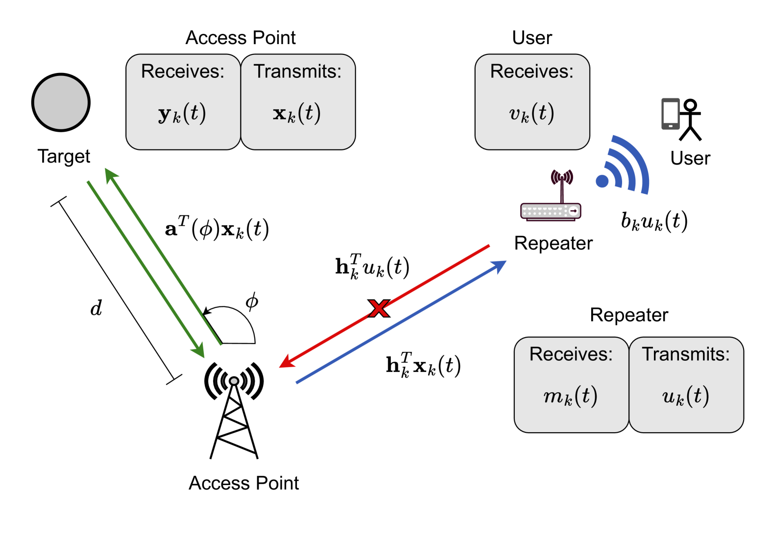
The system depicted in Figure 1 illustrates the downlink communication between one -antenna ISAC-AP and one single antenna user assisted by a single antenna NCR, as no direct link between the AP and user exists. Additionally, the AP is sensing one stationary target whose distance from the AP is unknown. All components of additive white Gaussian noise (AWGN) follow a distribution, where denotes a circularly-symmetric complex Gaussian distribution with zero mean and variance. In the case of noise vectors, all vector entries follow the aforementioned distribution.
II-A Signal models
It is considered an OFDM signal with symbol duration of s.t. , where , which is the time duration of a data symbol plus the time duration of the cyclic prefix.
II-A1 Transmitted signal from the AP
The vector transmitted from the AP at time is
| (1) |
where is the precoding vector, and is the OFDM symbols
| (2) |
In (2), is the number of sub-carriers, and is the sub-carrier frequency. The are the complex symbols to be transmitted, which adhere to the constraint: , i.e., the symbols have unit energy.
Additionally, the transmitted signal for a specific sub-carrier can be written as
| (3) |
where again, is a complex scalar representing one data symbol, for sub-carrier .
II-A2 Received and transmitted signal at the repeater
The received signal at the repeater, for sub-carrier , is modeled as
| (4) |
where is the complex channel coefficient vector between the AP and the repeater, and is AWGN.
Then, following an amplify-and-forward procedure with amplification gain , the repeater transmits
| (5) |
II-A3 Received signal at the AP
Considering a monostatic radar system consisting of a single ISAC AP, we can define to be the antenna array response vector for an angle of arrival/departure , towards the radar target, which allows us to write the received signal at the AP as
| (6) |
In (6), all vectors are and:
-
•
is the RCS which is distributed according to
-
•
is the large scale fading of the radar echo which depends on the distance to the radar target. Since we consider line of sight to the radar target, the path loss is modeled as
-
•
is the delay introduced from the round-trip path from the AP to the radar target, and back
-
•
is the complex channel coefficient vector between the AP and the repeater. Note that due to the reciprocity of the channel, this vector is equals the one in (4)
-
•
(t) is an AWGN noise vector
II-A4 Received signal at user
The received signal at the user is
| (7) |
where is the complex channel coefficient between the repeater and the user, and is AWGN.
In the following, we will consider sampled signals, since this will allow simple forms for the expressions in the later sections. In (2), if we set for , and a sub-carrier spacing of , then (2) can be written as
| (8) |
and, after sampling with frequency , we have that
| (9) |
Then, we can express and Thus, by applying the same reasoning, we rewrite (6) as
| (10) |
Since , this sampling procedure results in complex samples.
III User SINR
Using the received signal model for the single antenna user, we can derive an expression for the signal-to-interference-plus-noise ratio (SINR), , by expanding (7). Simultaneously, we also sample the received signal at the user resulting in
| (11) | ||||
| (12) | ||||
| (13) |
From this, the useful signal is
| (14) |
and the undesired terms are
| (15) |
Furthermore, we define the SINR as
| (16) |
thus, the unknown channel between the user and the AP, is estimable through uplink pilots from the user. Herein, we assume a perfect estimation is feasible, considering an approximately stationary user, and thus a relatively long coherence time. Therefore, the received useful signal power is expressed by
| (17) |
for a specific sub-carrier , and where is used. We also determine the denominator in Equation 16 as
| (18) |
where , and are the variances of and the AWGN, respectively.
Subsequently, the final expression for the SINR at the user is
| (19) |
and is summed over all , since there is no correlation between different sub-carriers. Although we assume perfect estimation of the total channel between user and AP, the individual channels and are still unknown and random.
IV Cramér-Rao Bound
The of the range, , to the target is denoted , and depends on the complex precoding vector , and the amplification gain of the NCR, , which is a positive real number. Furthermore, is the minimum user SINR constraint, respectively. Thus, the problem can be expressed as
| (20a) | ||||||
| s.t. | (20b) | |||||
| (20c) | ||||||
where is the maximum transmit power constraint on the AP. In (10), assuming that the angle towards the target, , is known, there are three unknown parameters: , , and . Importantly, and , where is the speed of light, contain no randomness.
The , of some parameter vector , is determined by the inverse of the Fisher information matrix, , whose th diagonal element corresponds to the of the th element of .
Herein, we consider a downlink pilot transmission phase conducted by the AP, where the round-trip channel to the repeater, and back, is estimated. This estimation, denoted , results in an estimation error per sub-carrier , consisting of i.i.d. entries, where is the channel estimation error variance. Accordingly, by replacing in (10), the received signal at the AP is
| (21) |
The term proves cumbersome to rigorously include in this analysis, therefore we will model this proportionally small attenuated, noise as where . Then, the precoded symbols are defined as . To facilitate the forthcoming derivations, we define the vectorized channel estimation error , and , where denotes the Kronecker product. The unknown interference is thus simplified to . Finally, using these definitions, and removing the known interference, we end up with
| (22) |
Hence, we define, for each time sample and sub-carrier ,
| (23) |
where and are the real and imaginary component of , respectively, and is the parameter vector.
Similarly, the covariance of (22) is
| (24) | ||||
| (25) |
and the subscripts and have been excluded from , due to the lack of dependence on the sub-carrier or time index.
Since the signal is complex Gaussian with distribution , the Fisher information matrix is given by Slepian-Bangs formula [14]
| (26) |
where extracts the real part of the expression. Note that the summations over and follows from different time instances and sub-carriers being independent.
Finally, by using (26) for , we can express the Fisher information matrix as
| (27) |
where
| (28) |
| (29) |
| (30) |
| (31) |
Importantly, and does not imply the real and imaginary component of , but rather the co-dependence of a distance estimate, with the real and imaginary part of , respectively.
Thereafter, we utilize Cramer’s Rule for matrix inversions to only calculate the necessary inverse element corresponding to
| (32) |
to finally express the optimization problem, in (20), as
| (33a) | |||||
| s.t. | (33b) | ||||
| (33c) | |||||
To solve this problem, we resort to gradient based optimization, not guaranteeing globally optimal solutions.
V Results
To evaluate the proposed joint precoder and NCR amplification gain design, 2000 trials were executed to gain numerical insights in how different parameters affected the . Channel coefficients were modeled as Rayleigh fading realizations, .
| Parameter | Value | Parameter | Value |
|---|---|---|---|
| dBm | dB | ||
| dBm | dB | ||
| dB | |||
| kHz |
All other parameters are specified in Table I. Initial values for the optimization parameters were , and a precoder with zero phase-shift and equal power for all antenna elements, i.e., . For comparisons, the same optimization problem was solved using a fixed gain , since this amplification gain can highly likely ensure precoders that meet the constraints for all the different parameter values used in the experiments.
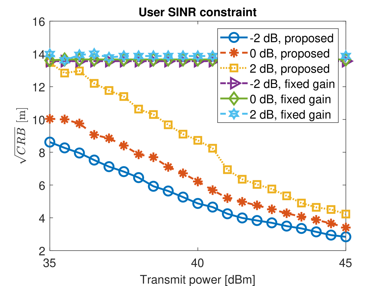
Figure 2 illustrates the square root of the versus the transmit power for different user SINR constraints. Note that, as expected, an increase in power always results in an improvement in the . Moreover, the fixed gain case presents no improvements, neither from increased power usage, nor from relaxing the use SINR constraint. This can be explained for the fact that as the power increases, the fixed gain interference from the repeater also increases as seen in (33a). Additionally, the change in the SINR constraint implicates that less power can be required to satisfy (33b), thus behave like an increase in power for the objective function, which as before have no effect on the , for the case of a fixed .
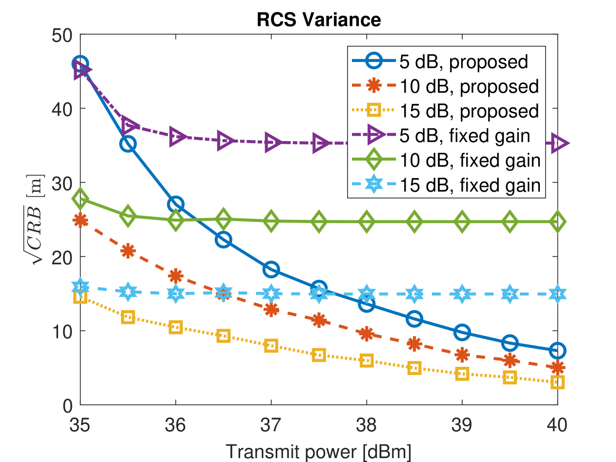
Figure 3 illustrates the square root of the versus the transmit power for three different RCS variances, for the proposed method and for the fixed amplification gain, respectively. Note that the proposed joint amplification gain and precoder optimization effectively reduces the when the transmit power is raised. Comparing to Figure 2, it is observed that more transmit power do not affect the static gain case, once the RCS variance represents how visible the target is to radar sensing attempts.
The actual distance to the target, used in the figures presented above, was meters, and Figure 3 used a user SINR constraint of dB, whilst Figure 2 used a RCS variance of dB. This results are obtained once an adjustable amplification gain will provide more space for fine tuning the system to reduce the interference from the repeater. Thus, the network is able to balance the beamforming for the communication user, with the gain of the repeater to prevent deterioration of sensing performance. An interesting future work would be to examine the opposite case, where the system favors the user in a communication-centric environment. Additionally, some areas of further analysis required is the simplified attenuated noise term in (21), and including the estimate of the unknown channel into the derivations.
VI Conclusions
In summary, this work analyzes the effect of a NCR being used for communication coverage extension, in a MIMO-OFDM ISAC setting. Particularly, the Cramér-Rao bound was determined for a distance estimator, and an optimization problem was formulated where the amplification gain of the NCR, and the precoder vector for the AP, were the optimization parameters. There were constraints on the transmit power and minimum user SINR. Numerical results showed that jointly choosing the amplification and precoder, can reduce the minimum variance achievable by unbiased estimators further than only calculating the precoders with a fixed NCR gain.
References
- [1] Reza Aghazadeh Ayoubi et al. “Network-Controlled Repeaters vs. Reconfigurable Intelligent Surfaces for 6G mmW Coverage Extension: A Simulative Comparison” In 2023 21st Mediterranean Communication and Computer Networking Conference (MedComNet), 2023, pp. 196–202
- [2] 3GPP “3rd Generation Partnership Project; Technical Specification Group Radio Access network; Study on NR network-controlled repeaters; (Release 18)”, 2022
- [3] Ertugrul Basar et al. “Reconfigurable Intelligent Surfaces for 6G: Emerging Hardware Architectures, Applications, and Open Challenges” In IEEE Vehicular Technology Magazine 19.3, 2024, pp. 27–47
- [4] Navid Abedini and Tao Luo “Smart and Green Networks Using Repeaters and Reconfigurable Intelligent Surfaces” In 2024 IEEE International Conference on Communications Workshops (ICC Workshops), 2024, pp. 1127–1133
- [5] Sara Willhammar et al. “Achieving Distributed MIMO Performance with Repeater-Assisted Cellular Massive MIMO”, 2024
- [6] Gabriel C.. Da Silva et al. “Impact of Network Deployment on the Performance of NCR-assisted Networks” In 2024 19th International Symposium on Wireless Communication Systems (ISWCS), 2024, pp. 1–6
- [7] Nuria González-Prelcic et al. “The Integrated Sensing and Communication Revolution for 6G: Vision, Techniques, and Applications” In Proceedings of the IEEE 112.7, 2024, pp. 676–723
- [8] Mohamed I. Ismail, Abdullah M. Shaheen, Mostafa M. Fouda and Ahmed S. Alwakeel “RIS-Assisted Integrated Sensing and Communication Systems: Joint Reflection and Beamforming Design” In IEEE Open Journal of the Communications Society 5, 2024, pp. 908–927
- [9] Chandan Kumar Sheemar et al. “Full-Duplex-Enabled Joint Communications and Sensing with Reconfigurable Intelligent Surfaces” arXiv, 2023
- [10] Erik G. Larsson and Jianan Bai “Stability Analysis of Interacting Wireless Repeaters” arXiv, 2024
- [11] Adham Sakhnini, Mamoun Guenach, André Bourdoux and Sofie Pollin “A Cramér-Rao Lower Bound for Analyzing the Localization Performance of a Multistatic Joint Radar-Communication System” In 2021 1st IEEE International Online Symposium on Joint Communications & Sensing (JC&S), 2021, pp. 1–5
- [12] Yoke Leen Sit and Thomas Zwick “MIMO OFDM radar with communication and interference cancellation features” In 2014 IEEE Radar Conference, 2014, pp. 0265–0268
- [13] Musa Furkan Keskin, Henk Wymeersch and Visa Koivunen “MIMO-OFDM Joint Radar-Communications: Is ICI Friend or Foe?” In IEEE Journal of Selected Topics in Signal Processing 15.6, 2021, pp. 1393–1408
- [14] S.. Kay “Fundamentals of Statistical Signal Processing: Estimation Theory” Prentice Hall, 1997
- [15] Yiyin Wang, Geert Leus and Alle-Jan Veen “Cramér-Rao bound for range estimation” In 2009 IEEE International Conference on Acoustics, Speech and Signal Processing, 2009, pp. 3301–3304