Intra-band entanglement-assisted cavity electro-optic quantum transducer
Abstract
Quantum transduction is a key technology for connecting different quantum technologies across varied frequencies. However, it remains a major challenge to overcome the high threshold for achieving positive capacity of traditional quantum transduction channels. Recently, an entanglement-assisted transducer was proposed based on a cavity-optic system [Opt. Quantum 2, 475 (2024)], where a modified bosonic loss channel was obtained, and the transduction efficiency can be enhanced by properly tuning the squeezing parameters. In this paper, we further identify three types of quantum channels enabled by this design, offering additional options for implementing the proposed transduction schemes. Compared to the transducers without entanglement assistance, the scheme also shows a great enhancement in the conversion bandwidth for achieving high quantum capacity, further increasing its value in practical applications.
I Introduction
Quantum transduction refers to the conversion of quantum information between different physical platforms, typically between microwave and optical photons [1, 2, 3]. The two systems differ widely in the energy scale and involve fundamentally different interaction mechanisms. The microwave quantum bits, based on superconducting circuits and other quantum processors, offer excellent coherence and scalability but lack intrinsic optical transitions [4, 5, 6], while the optical photon is ideal information carriers for long distance quantum communication. [7, 8, 9]. Quantum transduction bridges this gap by enabling coherent coupling between superconducting qubits and optical photons, which are essential for constructing large-scale quantum networks and distributed quantum architectures [10, 11, 12, 13, 14, 15].
In the past decades, significant progress has been made in quantum transduction based on various physical platforms, including electro-optics [16, 17, 18, 19, 20, 21, 22, 23], electro-optomechanics [24, 25, 26, 27, 28, 29, 30, 31, 32, 33, 34, 35, 36, 37], piezo-optomechanics [38, 39, 40], quantum magnonics [41, 42, 43, 44, 45], rare-earth-ions [46, 47, 48, 49] and atoms [50, 51, 52, 53, 54, 55, 56]. Theoretically, all quantum transduction systems can be regarded as a quantum channel. To reliably transmit encoded quantum information, a quantum channel must have a positive quantum capacity. This requirement indicates that a quantum transduction channel, generally modeled as a bosonic loss channel, must have both high channel transmissivity and low added noise [57]. However, the traditional direct quantum transducer (DQT), which linearly converts photons between different frequencies, faces significant challenges in reaching the positive quantum capacity threshold due to technological constraints, such as limited interaction strength and excessive thermal noises [58, 59, 60, 61, 62, 63, 64]. In order to enhance the performance of transduction channels, numerous approaches have been developed , such as entanglement based transduction [65, 66, 67, 68, 69, 70, 71, 72], adaptive feedforward control [73, 74], single mode squeezing enhanced transducer [75].
In Ref. [76], Haowei discussed a new scheme of an entanglement-assisted transducer based on a cavity electro-optic (EO) system. Specifically, for optical to microwave transduction, the scheme first entangles an ancilla with a probe in the microwave domain through a two-mode squeezer. The probe output, along with an optical encoding signal, is then sent into the EO system. The microwave output signal undergoes anti-squeezing with the ancilla mode using a second squeezer. It is shown that this process defines a new thermal loss channel whose quantum transduction capacity can be greatly enhanced. In this paper, we show the process actually induce more general transduction channels, namely random displacement, generalized thermal loss and thermal amplification channels. We perform a detailed analysis of the three types of transduction channels by adjusting the squeezing strengths of the two squeezers. The quantum capacities of different transduction channels are quantified in much wide parameter space, greatly expanding the potential scope of quantum transduction applications. Furthermore, we compare the cases with and without entanglement assistance under the non-resonant condition, demonstrating a significant improvement in quantum transduction bandwidth. These findings underscore the advantages of this scheme, paving the way of realizing a high bandwidth quantum transducer potentially in the near term.
II Quantum Transducer Based on Cavity Electro-Optic System
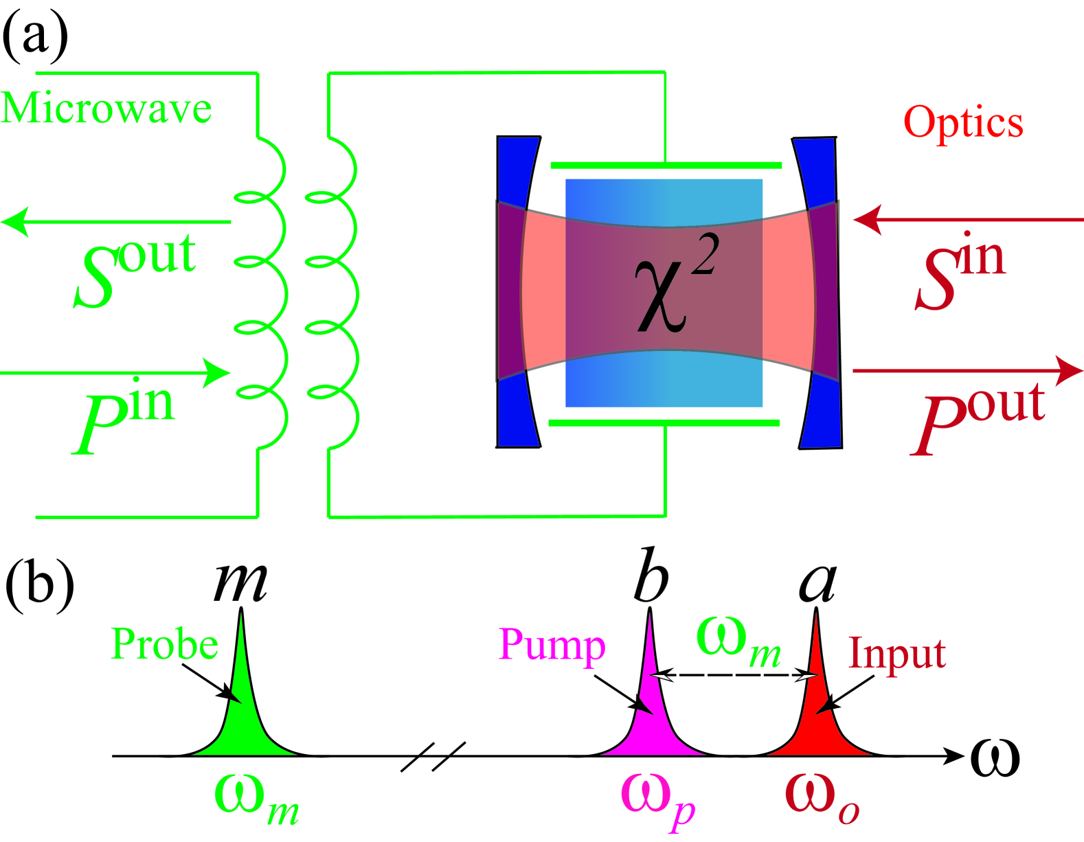
We begin by analyzing the quantum transducer based on the superconducting cavity EO system, as shown in Fig. 1(a). The optical cavity, made of material with Pockels nonliearity, is placed inside the capacitor of an LC microwave resonator. The electric field generated by the resonator alters the refractive index of the material in the optical cavity, thereby modulating its optical resonant frequency. Conversely, the optical fields within the cavity can induce a microwave field through optical rectification in the Pockels material, enabling bidirectional interaction between the optical and microwave domains [77, 78]. Moreover, the material’s nonlinear properties are utilized to enable the interaction between two specific optical modes and a microwave mode through frequency-matched three-wave mixing [16], as shown in Fig. 1(b). By strongly pumping the lower-frequency optical mode , with a frequency , a beam splitter interaction can be generated between the microwave mode and the higher-frequency optical mode. In the interaction picture, the total Hamiltonian is given as (let hereafter)
| (1) |
where and denote the annihilation operators for the optical and microwave modes, respectively. Here, the frequency-matching condition is satisfied, where () is the optical (microwave) resonant frequency. is the laser-enhanced coupling strength.
Now, we consider an optical input signal and a microwave probe in the EO system, and define as the fluctuation operator associated with the port, satisfying the commutation relation . The system dynamics are governed by the quantum Langevin equations (QLE), which are given by
| (2) |
Here, the total loss rate of the microwave (optical) mode is defined as , with the coupling and intrinsic loss rates and , respectively. Moreover, and are the quantum noise operators, which obey the correlation functions and , respectively. The mean thermal photon excitation number is given by , with the Boltzmann constant and the bath temperature . Notably, the thermal effects in the optical frequency range can be safely disregarded, because even at room temperature, the thermal photon number at THz is negligible.
Then applying the Fourier transform , the QLEs in Eq. (2) are transformed into the frequency domain as
| (3) |
where is the mode vector, while and are the input and noise vectors, respectively. Here, the corresponding coefficient matrices are given by
| (4) |
| (5) |
and
| (6) |
Combining with the standard input-output relation , we can figure out
| (7) |
with the transduction efficiency spectrum
| (8) |
and the probe transmissivity spectrum
Additionally, is the transmissivity of the loss port , which comes from the intrinsic loss of the two modes. These transmissivities satisfy the normalization condition .
The system forms a quantum transduction channel. Take the system on reasonance for example, it gives a single-mode bosonic loss channel with the transduction efficiency
| (10) |
and the probe transmissivity
| (11) |
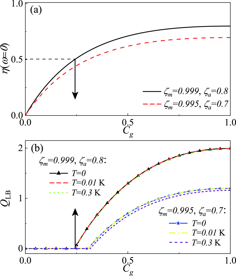
Here, we define the coupling ratio of the microwave (optical) mode as and the system cooperativity as . Fig. 2(a) illustrates how the cooperativity affects the transduction efficiency of the EO system under different coupling ratios.
To further describe the transduction performance of this system, we introduce the quantum capacity of a single-mode Gaussian channel, which is lower bounded by the following expression [75, 79, 80]
| (12) |
with the added noise (Detailed descriptions will be presented in Sec. IV) and the function . Here, is the noise variance of the random displacement channel. In the low-temperature limit, this lower bound becomes the exact quantum capacity of the channel.
The probe is assumed to be in the vacuum state. Fig. 2(b) shows how varies with the cooperativity under different coupling ratios and working temperatures. It can be seen that when the operating temperature is around , the quantum capacity of the transduction channel is almost identical to that in the low-temperature limit. This is because the thermal excitation number at microwave frequency is , which is negligible. As the temperature rises to , the negative impact of thermal noise on increases. However, recent experiments have demonstrated efficient cooling and several mK temperature can be achieved routinely [81, 82, 83].
Comparing Fig. 2(a) and 2(b), it can be observed that even for relatively high coupling ratios, the transduction efficiency must exceed to overcome the threshold for positive quantum capacity. However, the state-of-the-art still falls below the level indicated by the black arrow, highlighting the need for improved transduction schemes.
III Full Representation of the Transducer Model
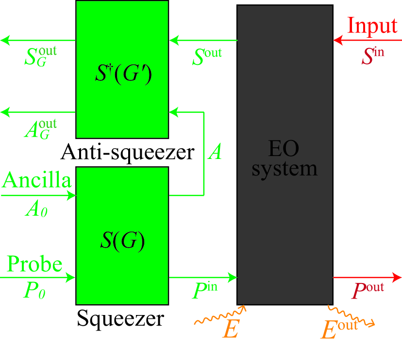
As illustrated in Fig. 3, the intra-band entanglement-assisted transducer consists of a nonlinear EO system situated between a squeezer and an anti-squeezer . The system involves three input fields: the probe , the ancilla , and the input signal . Here, the probe and the ancilla are both in the vacuum states and entangled through a two-mode squeezing interaction generated by . Subsequently, and are sent to the input ports of the EO system. Finally, the output and are anti-squeezed by , resulting in the final converted output in the microwave frequency. Notably, the final output is the sum of the three initial signals and the noise from the loss port , where each component can be altered by adjusting the squeezing strengths and .
We first assume the system is on resonant, thus, is omitted in the subsequent discussion. The non-resonant situation will be addressed later in the text. For the squeezers and , the corresponding input-output relations are given by
| (13) |
| (14) |
and
| (15) |
Combining with Eq. (7), we can obtain the full input-output relation for the entanglement-assisted transducer
where the four terms represent the contributions from the input signal, loss, probe, and ancilla ports, respectively. Interestingly, we see the transduction efficiency is enhanced by . In the following section, we will show that the squeezing strengths can also be tuned to realize different quantum transduction channels.
IV Characterization of intra-band entanglement-assisted transduction Channels
IV.1 Channel classification
To facilitate a clear analysis of transduction channels, we assume that , eliminating the loss port term in Eq. (III). Consequently, the final output is determined by the three input ports and is governed by the squeezer strengths and as well as the transduction efficiency . Now, we can basically classify the transduction channels based on the enhanced transduction efficiency : (i) generalized loss (GL) channel for ; (ii) generalized amplification (GA) channel for ; and (iii) random displacement (RDP) channel for .
In order to rigorously establish the input-output relations for these transduction channels, we define the total noise operator , which satisfies the canonical commutation relation . This requirement specifies that, for the GL channel, takes the form
| (17) |
while for the GA channel, the corresponding noise operator is given by
| (18) |
Thus, the transduction channels can be written in canonical form: (i) the GL channel
| (19) |
and (ii) the GA channel
| (20) |
The RDP channel exhibits an asymptotic behavior that bridges the GL and GA channels as , and its input-output relation is given by
| (21) | |||||
Notably, the GL and GA channels each have a unique case. Specifically, for the GL channel, when , the term in the total noise operator is eliminated. The final output simplifies to
| (22) |
which corresponds to the pure-loss (PL) channel in the low-temperature limit or the thermal-loss (TL) channel at non-zero temperature. This is exactly the transduction channel that Ref. [76] discussed. Moreover, for GA channel, when the term in the total noise operator is eliminated, i.e., , the output simplifies to
| (23) |
which corresponds to the pure-amplification (PA) channel in the low-temperature limit and the thermal-amplification (TA) channel at non-zero temperature.
IV.2 Quantum capacity versus squeezer strengths
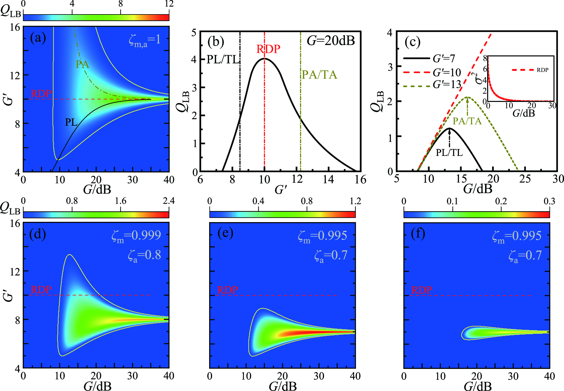
Based on Eq. (12), we can obtain the quantum capacity lower bound of the entanglement-assisted transducer by substituting the transduction efficiency and the EO system’s added noise with the enhanced transduction efficiency and its corresponding noise , respectively. Here, is determined by the new bosonic mode . In this subsection, we fix . Fig. 4(a) shows how varies with respect to squeezer strengths and . Remarkably, a large parameter regime for positive quantum capacity can be achieved, as enclosed by the yellow curve. Here, the region above the red-dashed line, which represents the RDP channel, corresponds to the GA channel, while the region below corresponds to the GL channel. It is noticeable that, for a fixed , reaches its maximum value at (RDP channel). Moreover, the boundary exhibits a convex shape along the curves corresponding to the PL/TL and PA/TA channels. This indicates that, for a fixed , the local maximum values of are located on these curves, highlighting their significance in optimizing the transduction channel. As increases, the range of where becomes narrower. However, the maximum value of increases at the same time, reflecting the effective suppression of noise in the RDP channel with larger .
Next, we further investigate the respective relationships of with and . As shown in Fig. 4(b), for a fixed , the region to the left of the red vertical line, which corresponds to the RDP channel, represents the GL channel, while the region to the right represents the GA channel. The two vertical lines within the GL and GA channels correspond to the PL/TL and PA/TA channels, respectively. Consistent with the situation in Fig. 4(a), the of the GL channel increases with , reaching a maximum at the RDP channel, and then decreases as the channel transitions into the GA regime with larger . This trend implies that for the GL channel, the amplification of the input signal by is prominent, whereas in the GA channel, the noise amplification gradually becomes the dominant effect as increases. Moreover, for a fixed , Fig. 4(c) illustrates how the quantum capacities of the GL, RDP, and GA channels vary as a function of . In particular, the GL (GA) channel reaches its maximum value when it operates as a PL/TL (PA/TA) channel, which is indicated by the arrow on the curve of (). At , we get the RDP channel with a unit transmissivity, and its added noise is linearly suppressed as increases (see the inset of Fig. 4(c)). Consequently, the system’s quantum capacity exhibits a log-linear dependence on .
When the loss port is taken into account, the noise term in Eq. (III) adversely affects the quantum capacity of the transduction channel. In fact, in the final output , the amplification provided by boosts not only the input signal but also the noise operator . Consequently, at higher values the channel becomes increasingly sensitive to , resulting in a more pronounced reduction in and a downward shift of its maximum, which appears in the lower region of the RDP channel, as depicted in Fig. 4(d) and 4(e). Correspondingly, the boundary contracts more noticeably as increases. At non-zero operating temperature, the thermal noise further diminishes the overall of the transduction channel, as illustrated in Fig. 4(f).
V Comparative Analysis under the Non-Resonant Condition
In this section, we compare the quantum capacity of the transducer with and without entanglement assistance under the non-resonant condition. Here, we focus on the PL channel in the low-temperature limit. Serving as auxiliary resources, the two squeezers play complementary roles in the entanglement-assisted transducer. On one hand, the squeezer strength can effectively enhance the transduction efficiency . On the other hand, as increases, the noise introduced by the probe can be effectively suppressed. Consequently, the PL channel implemented by the entanglement-assisted transducer shows a significant improvement in the quantum capacity compared to the bare EO system. Additionally, the transduction bandwidth corresponding to the positive quantum capacity is also notably increased.
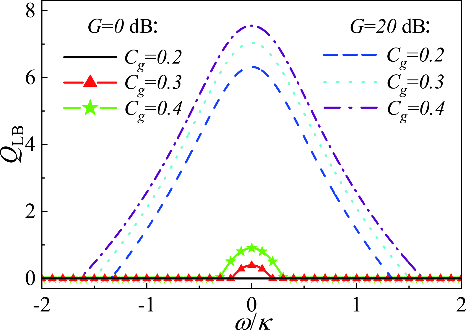
Without loss of generality, we set . According to the transduction efficiency of the EO system under the non-resonant condition Eq. (8), the frequency-domain distributions of the quantum capacity for the PL channel implemented by both the bare EO system and the entanglement-assisted transducer are illustrated in Fig. 5. In the absence of entanglement assistance ( dB), the bare EO system fails to achieve a positive quantum capacity when , where . In contrast, the entanglement-assisted transducer can realize a PL channel with a high-bandwidth positive quantum capacity. As the cooperativity increases, the bare EO system begins to exhibit positive quantum capacity near the resonant frequency, while the entanglement-assisted transducer attains a higher quantum capacity over a much broader bandwidth. Notably, for systems with lower , entanglement assistance yields a more pronounced enhancement in the effective bandwidth, thereby enhancing the transducer’s practical applicability.
VI Conclusion
In conclusion, we study an entanglement-assisted quantum transducer based on a cavity EO system to overcome the high threshold required for achieving positive quantum capacity. By introducing an assist mode and two squeezers, the transduction efficiency is significantly enhanced, greatly lowering the threshold for the positive quantum capacity compared to the bare EO system. We presented a detailed analysis of the transducer, exploring the three types of transduction channels achievable through the adjustment of the squeezing strength of the two squeezers. Moreover, we examine how a broad variation in the two squeezing strengths influences the quantum capacities of different transduction channels, clarifying the conditions needed to fully optimize the transducer’s performance. Additionally, the entanglement-assisted transducer has a marked improvement in the bandwidth for achieving high quantum capacity. This advancement is crucial for constructing high-bandwidth DQTs, while ensuring high-fidelity signal transduction. Our study provides a full theoretical framework for analyzing intra-band entanglement-assisted quantum transduction scheme, which unlocks more potentials of its application in future quantum technologies.
Acknowledgements.
This work was supported the start-ups from Xi’an Jiaotong University (Grant No. 11301224010717).References
- Lauk et al. [2020] N. Lauk, N. Sinclair, S. Barzanjeh, J. P. Covey, M. Saffman, M. Spiropulu, and C. Simon, Perspectives on quantum transduction, Quantum Sci. and Technol. 5, 020501 (2020).
- Awschalom et al. [2021] D. Awschalom, K. K. Berggren, H. Bernien, S. Bhave, L. D. Carr, P. Davids, S. E. Economou, D. Englund, A. Faraon, M. Fejer, S. Guha, M. V. Gustafsson, E. Hu, L. Jiang, J. Kim, B. Korzh, P. Kumar, P. G. Kwiat, M. Lončar, M. D. Lukin, D. A. Miller, C. Monroe, S. W. Nam, P. Narang, J. S. Orcutt, M. G. Raymer, A. H. Safavi-Naeini, M. Spiropulu, K. Srinivasan, S. Sun, J. Vučković, E. Waks, R. Walsworth, A. M. Weiner, and Z. Zhang, Development of quantum interconnects (quics) for next-generation information technologies, PRX Quantum 2, 017002 (2021).
- Lambert et al. [2020] N. J. Lambert, A. Rueda, F. Sedlmeir, and H. G. L. Schwefel, Coherent conversion between microwave and optical photons—an overview of physical implementations, Adv. Quantum Technol. 3, 1900077 (2020).
- Blais et al. [2021] A. Blais, A. L. Grimsmo, S. M. Girvin, and A. Wallraff, Circuit quantum electrodynamics, Rev. Mod. Phys. 93, 025005 (2021).
- Schoelkopf and Girvin [2008] R. J. Schoelkopf and S. M. Girvin, Wiring up quantum systems, Nature 451, 664 (2008).
- Wendin [2017] G. Wendin, Quantum information processing with superconducting circuits: a review, Rep. Prog. Phys. 80, 106001 (2017).
- Takesue et al. [2015] H. Takesue, S. D. Dyer, M. J. Stevens, V. Verma, R. P. Mirin, and S. W. Nam, Quantum teleportation over 100 km of fiber using highly efficient superconducting nanowire single-photon detectors, Optica 2, 832 (2015).
- Yin et al. [2017] J. Yin, Y. Cao, Y.-H. Li, S.-K. Liao, L. Zhang, J.-G. Ren, W.-Q. Cai, W.-Y. Liu, B. Li, H. Dai, G.-B. Li, Q.-M. Lu, Y.-H. Gong, Y. Xu, S.-L. Li, F.-Z. Li, Y.-Y. Yin, Z.-Q. Jiang, M. Li, J.-J. Jia, G. Ren, D. He, Y.-L. Zhou, X.-X. Zhang, N. Wang, X. Chang, Z.-C. Zhu, N.-L. Liu, Y.-A. Chen, C.-Y. Lu, R. Shu, C.-Z. Peng, J.-Y. Wang, and J.-W. Pan, Satellite-based entanglement distribution over 1200 kilometers, Science 356, 1140 (2017).
- Chen et al. [2021] Y.-A. Chen, Q. Zhang, T.-Y. Chen, W.-Q. Cai, S.-K. Liao, J. Zhang, K. Chen, J. Yin, J.-G. Ren, Z. Chen, S.-L. Han, Q. Yu, K. Liang, F. Zhou, X. Yuan, M.-S. Zhao, T.-Y. Wang, X. Jiang, L. Zhang, W.-Y. Liu, Y. Li, Q. Shen, Y. Cao, C.-Y. Lu, R. Shu, J.-Y. Wang, L. Li, N.-L. Liu, F. Xu, X.-B. Wang, C.-Z. Peng, and J.-W. Pan, An integrated space-to-ground quantum communication network over 4,600 kilometres, Nature 589, 214 (2021).
- Elliott [2002] C. Elliott, Building the quantum network, New J. Phys. 4, 46 (2002).
- Kómár et al. [2014] P. Kómár, E. M. Kessler, M. Bishof, L. Jiang, A. S. Sørensen, J. Ye, and M. D. Lukin, A quantum network of clocks, Nat. Phys. 10, 582 (2014).
- Simon [2017] C. Simon, Towards a global quantum network, Nat. Phys. 11, 678 (2017).
- Cirac et al. [1997] J. I. Cirac, P. Zoller, H. J. Kimble, and H. Mabuchi, Quantum state transfer and entanglement distribution among distant nodes in a quantum network, Phys. Rev. Lett. 78, 3221 (1997).
- Kimble [2008] H. J. Kimble, The quantum internet, Nature 453, 1023 (2008).
- Zhong [2024] C. Zhong, Efficiently catching entangled microwave photons from a quantum transducer with shaped optical pumps, Phys. Rev. Res. 6, 043196 (2024).
- Fan et al. [2018] L. Fan, C.-L. Zou, R. Cheng, X. Guo, X. Han, Z. Gong, S. Wang, and H. X. Tang, Superconducting cavity electro-optics: A platform for coherent photon conversion between superconducting and photonic circuits, Sci. Adv. 4, eaar4994 (2018).
- Soltani et al. [2017] M. Soltani, M. Zhang, C. Ryan, G. J. Ribeill, C. Wang, and M. Loncar, Efficient quantum microwave-to-optical conversion using electro-optic nanophotonic coupled resonators, Phys. Rev. A 96, 043808 (2017).
- Xu et al. [2021] Y. Xu, A. A. Sayem, L. Fan, C.-L. Zou, S. Wang, R. Cheng, W. Fu, L. Yang, M. Xu, and H. X. Tang, Bidirectional interconversion of microwave and light with thin-film lithium niobate, Nat. Commun. 12, 10.1038/s41467-021-24809-y (2021).
- Fu et al. [2021] W. Fu, M. Xu, X. Liu, C.-L. Zou, C. Zhong, X. Han, M. Shen, Y. Xu, R. Cheng, S. Wang, L. Jiang, and H. X. Tang, Cavity electro-optic circuit for microwave-to-optical conversion in the quantum ground state, Phys. Rev. A 103, 053504 (2021).
- Sahu et al. [2022] R. Sahu, W. Hease, A. Rueda, G. Arnold, L. Qiu, and J. M. Fink, Quantum-enabled operation of a microwave-optical interface, Nat. Commun. 13, 1276 (2022).
- Tsuchimoto et al. [2022] Y. Tsuchimoto, Z. Sun, E. Togan, S. Fält, W. Wegscheider, A. Wallraff, K. Ensslin, A. m. c. İmamoğlu, and M. Kroner, Large-bandwidth transduction between an optical single quantum dot molecule and a superconducting resonator, PRX Quantum 3, 030336 (2022).
- Javerzac-Galy et al. [2016] C. Javerzac-Galy, K. Plekhanov, N. R. Bernier, L. D. Toth, A. K. Feofanov, and T. J. Kippenberg, On-chip microwave-to-optical quantum coherent converter based on a superconducting resonator coupled to an electro-optic microresonator, Phys. Rev. A 94, 053815 (2016).
- McKenna et al. [2020] T. P. McKenna, J. D. Witmer, R. N. Patel, W. Jiang, R. V. Laer, P. Arrangoiz-Arriola, E. A. Wollack, J. F. Herrmann, and A. H. Safavi-Naeini, Cryogenic microwave-to-optical conversion using a triply resonant lithium-niobate-on-sapphire transducer, Optica 7, 1737 (2020).
- Regal and Lehnert [2011] C. A. Regal and K. W. Lehnert, From cavity electromechanics to cavity optomechanics, J. Phys.: Conf. Ser. 264, 012025 (2011).
- Bochmann et al. [2013] J. Bochmann, A. Vainsencher, D. D. Awschalom, and A. N. Cleland, Nanomechanical coupling between microwave and optical photons, Nat. Phys. 9, 712 (2013).
- Midolo et al. [2018] L. Midolo, A. Schliesser, and A. Fiore, Nano-opto-electro-mechanical systems, Nat. Nanotechnol. 13, 11 (2018).
- Andrews et al. [2014] R. W. Andrews, R. W. Peterson, T. P. Purdy, K. Cicak, R. W. Simmonds, C. A. Regal, and K. W. Lehnert, Bidirectional and efficient conversion between microwave and optical light, Nat. Phys. 10, 321 (2014).
- Arnold et al. [2020] G. Arnold, M. Wulf, S. Barzanjeh, E. S. Redchenko, A. Rueda, W. J. Hease, F. Hassani, and J. M. Fink, Converting microwave and telecom photons with a silicon photonic nanomechanical interface, Nat. Commun. 11, 10.1038/s41467-020-18269-z (2020).
- Tian and Wang [2010] L. Tian and H. Wang, Optical wavelength conversion of quantum states with optomechanics, Phys. Rev. A 82, 053806 (2010).
- Tian [2015] L. Tian, Optoelectromechanical transducer: Reversible conversion between microwave and optical photons, Annalen der Physik 527, 1 (2015).
- Taylor et al. [2011] J. M. Taylor, A. S. Sørensen, C. M. Marcus, and E. S. Polzik, Laser cooling and optical detection of excitations in a electrical circuit, Phys. Rev. Lett. 107, 273601 (2011).
- Barzanjeh et al. [2011] S. Barzanjeh, D. Vitali, P. Tombesi, and G. J. Milburn, Entangling optical and microwave cavity modes by means of a nanomechanical resonator, Phys. Rev. A 84, 042342 (2011).
- Wang and Clerk [2012] Y.-D. Wang and A. A. Clerk, Using interference for high fidelity quantum state transfer in optomechanics, Phys. Rev. Lett. 108, 153603 (2012).
- Tian [2012] L. Tian, Adiabatic state conversion and pulse transmission in optomechanical systems, Phys. Rev. Lett. 108, 153604 (2012).
- Bagci et al. [2014] T. Bagci, A. Simonsen, S. Schmid, L. G. Villanueva, E. Zeuthen, J. Appel, J. M. Taylor, A. Sørensen, K. Usami, A. Schliesser, and E. S. Polzik, Optical detection of radio waves through a nanomechanical transducer, Nature 507, 81 (2014).
- Winger et al. [2011] M. Winger, T. D. Blasius, T. P. M. Alegre, A. H. Safavi-Naeini, S. Meenehan, J. Cohen, S. Stobbe, and O. Painter, A chip-scale integrated cavity-electro-optomechanics platform, Opt. Express 19, 24905 (2011).
- Pitanti et al. [2015] A. Pitanti, J. M. Fink, A. H. Safavi-Naeini, J. T. Hill, C. U. Lei, A. Tredicucci, and O. Painter, Strong opto-electro-mechanical coupling in a silicon photonic crystal cavity, Opt. Express 23, 3196 (2015).
- Han et al. [2020] X. Han, W. Fu, C. Zhong, C.-L. Zou, Y. Xu, A. A. Sayem, M. Xu, S. Wang, R. Cheng, L. Jiang, and H. X. Tang, Cavity piezo-mechanics for superconducting-nanophotonic quantum interface, Nat. Commun. 11, 10.1038/s41467-020-17053-3 (2020).
- Mirhosseini et al. [2020] M. Mirhosseini, A. Sipahigil, M. Kalaee, and O. Painter, Superconducting qubit to optical photon transduction, Nature 588, 599 (2020).
- Jiang et al. [2020] W. Jiang, C. J. Sarabalis, Y. D. Dahmani, R. N. Patel, F. M. Mayor, T. P. McKenna, R. Van Laer, and A. H. Safavi-Naeini, Efficient bidirectional piezo-optomechanical transduction between microwave and optical frequency, Nat. Commun. 11, 1166 (2020).
- Zhu et al. [2020] N. Zhu, X. Zhang, X. Han, C.-L. Zou, C. Zhong, C.-H. Wang, L. Jiang, and H. X. Tang, Waveguide cavity optomagnonics for microwave-to-optics conversion, Optica 7, 1291 (2020).
- Hisatomi et al. [2016] R. Hisatomi, A. Osada, Y. Tabuchi, T. Ishikawa, A. Noguchi, R. Yamazaki, K. Usami, and Y. Nakamura, Bidirectional conversion between microwave and light via ferromagnetic magnons, Phys. Rev. B 93, 174427 (2016).
- Zhang et al. [2016] X. Zhang, N. Zhu, C.-L. Zou, and H. X. Tang, Optomagnonic whispering gallery microresonators, Phys. Rev. Lett. 117, 123605 (2016).
- Zhang et al. [2014] X. Zhang, C.-L. Zou, L. Jiang, and H. X. Tang, Strongly coupled magnons and cavity microwave photons, Phys. Rev. Lett. 113, 156401 (2014).
- Yan et al. [2024] Y.-T. Yan, D.-W. Wang, J. Yang, and L. Zhou, Microwave-to-optical conversion and amplification in cavity optomagnonics system, Ann. Phys. 536, 2400271 (2024).
- Everts et al. [2019] J. R. Everts, M. C. Berrington, R. L. Ahlefeldt, and J. J. Longdell, Microwave to optical photon conversion via fully concentrated rare-earth-ion crystals, Phys. Rev. A 99, 063830 (2019).
- O’Brien et al. [2014] C. O’Brien, N. Lauk, S. Blum, G. Morigi, and M. Fleischhauer, Interfacing superconducting qubits and telecom photons via a rare-earth-doped crystal, Phys. Rev. Lett. 113, 063603 (2014).
- Fernandez-Gonzalvo et al. [2015] X. Fernandez-Gonzalvo, Y.-H. Chen, C. Yin, S. Rogge, and J. J. Longdell, Coherent frequency up-conversion of microwaves to the optical telecommunications band in an er:yso crystal, Phys. Rev. A 92, 062313 (2015).
- Williamson et al. [2014] L. A. Williamson, Y.-H. Chen, and J. J. Longdell, Magneto-optic modulator with unit quantum efficiency, Phys. Rev. Lett. 113, 203601 (2014).
- Han et al. [2018] J. Han, T. Vogt, C. Gross, D. Jaksch, M. Kiffner, and W. Li, Coherent microwave-to-optical conversion via six-wave mixing in rydberg atoms, Phys. Rev. Lett. 120, 093201 (2018).
- Bartholomew et al. [2020] J. G. Bartholomew, J. Rochman, T. Xie, J. M. Kindem, A. Ruskuc, I. Craiciu, M. Lei, and A. Faraon, On-chip coherent microwave-to-optical transduction mediated by ytterbium in yvo4, Nat. Commun. 11, 10.1038/s41467-020-16996-x (2020).
- Adwaith et al. [2019] K. V. Adwaith, A. Karigowda, C. Manwatkar, F. Bretenaker, and A. Narayanan, Coherent microwave-to-optical conversion by three-wave mixing in a room temperature atomic system, Opt. Lett. 44, 33 (2019).
- Vogt et al. [2019] T. Vogt, C. Gross, J. Han, S. B. Pal, M. Lam, M. Kiffner, and W. Li, Efficient microwave-to-optical conversion using rydberg atoms, Phys. Rev. A 99, 023832 (2019).
- Hafezi et al. [2012] M. Hafezi, Z. Kim, S. L. Rolston, L. A. Orozco, B. L. Lev, and J. M. Taylor, Atomic interface between microwave and optical photons, Phys. Rev. A 85, 020302 (2012).
- Gard et al. [2017] B. T. Gard, K. Jacobs, R. McDermott, and M. Saffman, Microwave-to-optical frequency conversion using a cesium atom coupled to a superconducting resonator, Phys. Rev. A 96, 013833 (2017).
- Kiffner et al. [2016] M. Kiffner, A. Feizpour, K. T. Kaczmarek, D. Jaksch, and J. Nunn, Two-way interconversion of millimeter-wave and optical fields in rydberg gases, New J. Phys. 18, 093030 (2016).
- Weedbrook et al. [2012] C. Weedbrook, S. Pirandola, R. García-Patrón, N. J. Cerf, T. C. Ralph, J. H. Shapiro, and S. Lloyd, Gaussian quantum information, Rev. Mod. Phys. 84, 621 (2012).
- Holzgrafe et al. [2020] J. Holzgrafe, N. Sinclair, D. Zhu, A. Shams-Ansari, M. Colangelo, Y. Hu, M. Zhang, K. K. Berggren, and M. Lončar, Cavity electro-optics in thin-film lithium niobate for efficient microwave-to-optical transduction, Optica (2020).
- Brubaker et al. [2022] B. M. Brubaker, J. M. Kindem, M. D. Urmey, S. Mittal, R. D. Delaney, P. S. Burns, M. R. Vissers, K. W. Lehnert, and C. A. Regal, Optomechanical ground-state cooling in a continuous and efficient electro-optic transducer, Phys. Rev. X 12, 021062 (2022).
- Qiu et al. [2023] L. Qiu, R. Sahu, W. Hease, G. Arnold, and J. M. Fink, Coherent optical control of a superconducting microwave cavity via electro-optical dynamical back-action, Nat. Commun. 14, 10.1038/s41467-023-39493-3 (2023).
- Sahu et al. [2023] R. Sahu, L. Qiu, W. Hease, G. Arnold, Y. Minoguchi, P. Rabl, and J. M. Fink, Entangling microwaves with light, Science 380, 718 (2023).
- Han et al. [2016] X. Han, C.-L. Zou, and H. X. Tang, Multimode strong coupling in superconducting cavity piezoelectromechanics, Phys. Rev. Lett. 117, 123603 (2016).
- Forsch et al. [2019] M. Forsch, R. Stockill, A. Wallucks, I. Marinković, C. Gärtner, R. A. Norte, F. van Otten, A. Fiore, K. Srinivasan, and S. Gröblacher, Microwave-to-optics conversion using a mechanical oscillator in its quantum ground state, Nat. Phys. 16, 69 (2019).
- Vainsencher et al. [2016] A. Vainsencher, K. J. Satzinger, G. A. Peairs, and A. N. Cleland, Bi-directional conversion between microwave and optical frequencies in a piezoelectric optomechanical device, Appl. Phys. Lett. 109, 10.1063/1.4955408 (2016).
- Barzanjeh et al. [2012] S. Barzanjeh, M. Abdi, G. J. Milburn, P. Tombesi, and D. Vitali, Reversible optical-to-microwave quantum interface, Phys. Rev. Lett. 109, 130503 (2012).
- Zhong et al. [2020] C. Zhong, Z. Wang, C. Zou, M. Zhang, X. Han, W. Fu, M. Xu, S. Shankar, M. H. Devoret, H. X. Tang, and L. Jiang, Proposal for heralded generation and detection of entangled microwave–optical-photon pairs, Phys. Rev. Lett. 124, 010511 (2020).
- Rueda et al. [2019] A. Rueda, W. Hease, S. Barzanjeh, and J. M. Fink, Electro-optic entanglement source for microwave to telecom quantum state transfer, npj Quantum Inf. 5, 10.1038/s41534-019-0220-5 (2019).
- Zhong et al. [2022a] C. Zhong, X. Han, and L. Jiang, Microwave and optical entanglement for quantum transduction with electro-optomechanics, Phys. Rev. Appl. 18, 054061 (2022a).
- Wu et al. [2021] J. Wu, C. Cui, L. Fan, and Q. Zhuang, Deterministic microwave-optical transduction based on quantum teleportation, Phys. Rev. Appl. 16, 064044 (2021).
- Valivarthi et al. [2014] R. Valivarthi, I. Lucio-Martinez, A. Rubenok, P. Chan, F. Marsili, V. B. Verma, M. D. Shaw, J. A. Stern, J. A. Slater, D. Oblak, S. W. Nam, and W. Tittel, Efficient bell state analyzer for time-bin qubits with fast-recovery wsi superconducting single photon detectors, Opt. Express 22, 24497 (2014).
- Pirandola et al. [2015] S. Pirandola, J. Eisert, C. Weedbrook, A. Furusawa, and S. L. Braunstein, Advances in quantum teleportation, Nat. Photonics 9, 641 (2015).
- Zhong et al. [2024] C. Zhong, F. Li, S. Meesala, S. Wood, D. Lake, O. Painter, and L. Jiang, Microwave-optical entanglement from pulse-pumped electro-optomechanics, Phys. Rev. Appl. 22, 064047 (2024).
- Higginbotham et al. [2018] A. P. Higginbotham, P. S. Burns, M. D. Urmey, R. W. Peterson, N. S. Kampel, B. M. Brubaker, G. Smith, K. W. Lehnert, and C. A. Regal, Harnessing electro-optic correlations in an efficient mechanical converter, Nat. Phys. 14, 1038 (2018).
- Zhang et al. [2018] M. Zhang, C.-L. Zou, and L. Jiang, Quantum transduction with adaptive control, Phys. Rev. Lett. 120, 020502 (2018).
- Zhong et al. [2022b] C. Zhong, M. Xu, A. Clerk, H. X. Tang, and L. Jiang, Quantum transduction is enhanced by single mode squeezing operators, Phys. Rev. Res. 4, L042013 (2022b).
- Shi and Zhuang [2024] H. Shi and Q. Zhuang, Overcoming the fundamental limit of quantum transduction via intraband entanglement, Opt. Quantum 2, 475 (2024).
- Tsang [2010] M. Tsang, Cavity quantum electro-optics, Phys. Rev. A 81, 063837 (2010).
- Tsang [2011] M. Tsang, Cavity quantum electro-optics. ii. input-output relations between traveling optical and microwave fields, Phys. Rev. A 84, 043845 (2011).
- Holevo and Werner [2001] A. S. Holevo and R. F. Werner, Evaluating capacities of bosonic gaussian channels, Phys. Rev. A 63, 032312 (2001).
- Pirandola et al. [2009] S. Pirandola, R. García-Patrón, S. L. Braunstein, and S. Lloyd, Direct and reverse secret-key capacities of a quantum channel, Phys. Rev. Lett. 102, 050503 (2009).
- Huang and Agarwal [2009] S. Huang and G. S. Agarwal, Enhancement of cavity cooling of a micromechanical mirror using parametric interactions, Phys. Rev. A 79, 013821 (2009).
- Aspelmeyer et al. [2014] M. Aspelmeyer, T. J. Kippenberg, and F. Marquardt, Cavity optomechanics, Rev. Mod. Phys. 86, 1391 (2014).
- Clark et al. [2017] J. B. Clark, F. Lecocq, R. W. Simmonds, J. Aumentado, and J. D. Teufel, Sideband cooling beyond the quantum backaction limit with squeezed light, Nature 541, 191 (2017).