Sensing-Based Beamformed Resource Allocation in Standalone Millimeter-Wave Vehicular Networks
Abstract
In 3GPP New Radio (NR) Vehicle-to-Everything (V2X), the new standard for next-generation vehicular networks, vehicles can autonomously select sidelink resources for data transmission, which permits network operations without cellular coverage. However, standalone resource allocation is uncoordinated, and is complicated by the high mobility of the nodes that may introduce unforeseen channel collisions (e.g., when a transmitting vehicle changes path) or free up resources (e.g., when a vehicle moves outside of the communication area). Moreover, unscheduled resource allocation is prone to the hidden node and exposed node problems, which are particularly critical considering directional transmissions. In this paper, we implement and demonstrate a new channel access scheme for NR V2X in Frequency Range 2 (FR2), i.e., at millimeter wave (mmWave) frequencies, based on directional and beamformed transmissions along with Sidelink Control Information (SCI) to select resources for transmission. We prove via simulation that this approach can reduce the probability of collision for resource allocation, compared to a baseline solution that does not configure SCI transmissions.
Index Terms:
Millimeter wave (mmWave); Vehicle-to-Vehicle (V2V)communication; Resource allocation; 5G NR V2X.I Introduction
In recent years, with the increasing number of vehicles on the road, the research community has been focusing on Connected and Autonomous Vehicles (CAVs) to improve safety and driving efficiency [1, 2]. The potential of CAVs can be fully unleashed through Vehicle-to-Everything (V2X) communication, which includes, for example, communication to and from cellular base stations (i.e., Vehicle-to-Infrastructure (V2I)) and among vehicles (i.e., Vehicle-to-Vehicle (V2V)). On this front, the 3rd Generation Partnership Project (3GPP) is promoting the New Radio (NR) V2X standard to support V2X communication [3]. Along the lines of Rel-17 5G NR Uu specifications at 60 GHz, Rel-16 NR V2X involves sidelink transmissions in Frequency Range 2 (FR2) [4], i.e., in the lower part of the millimeter wave (mmWave) spectrum [5, 6]. In particular, communication in the unlicensed bands in FR2, especially at 60 GHz, is gaining momentum as an approach to alleviate spectrum scarcity, but also to promote better return of investment for service delivery.
As far as resource allocation is concerned, NR V2X defines two modes for the selection of sidelink resources [7]. In particular, in NR V2X Mode 2 vehicles can autonomously select their sidelink resources for data transmission, which permits network operations without cellular coverage. Specifically, vehicles determine the candidate set of resources based on Sidelink Control Information (SCI) received from other vehicles, and on the Reference Signal Received Power (RSRP) measured over the demodulation reference signals associated with the Physical Sidelink Shared Channel (PSSCH) or the Physical Sidelink Control Channel (PSCCH) [8]. However, NR V2X in FR2 introduces additional challenges for resource allocation [9]. Most importantly, the severe path loss in these bands, and especially at 60 GHz due to oxygen absorption, require the vehicles to maintain directional transmissions via beamforming [10]. While this approach can reduce interference and collision, nodes may be listening to one specific direction, and receive partial SCI (or no SCI at all) in the rest of the angular space. which complicates resource allocation. Moreover, channel dynamics in FR2 may cause SCI to become outdated. Furthermore, NR V2X channel access is prone to the hidden node and exposed node problems. On the one hand, communication in FR2 helps mitigate the exposed node problem, as a receiving node will detect transmissions only within its (narrow) beam. On the other hand, the use of directional transmissions in FR2 exacerbates the hidden node problem, as vehicles may fail to detect transmissions outside of their beams.
Recently, the use of FR2 in V2X has been explored in the literature, mainly to support high-capacity transmissions for cooperative perception [11, 12, 13]. However, most of these works do not consider the impact of directionality on the control plane, especially for resource allocation, or even exploit spatial diversity in FR2.
In this work, we implement and evaluate a resource allocation scheme for NR V2X Mode 2 at 60 GHz based on directional and beamformed communication. Specifically, each node receives SCI in the direction of transmission and in the paired direction, which indicates the resources being used for concurrent transmissions. These resources are labeled as blocked and will not be selected, thereby reducing the probability of collision. While calibration results from the 3GPP only look at omnidirectional sensing, the novelty of this paper lies in the fact that we quantify resource allocation considering directional SCI transmissions, which is in line with the standardization activities on NR V2X towards Rel-19. We run simulations as a function of the application rate, the density of vehicles, the antenna architecture, and the frame structure. We demonstrate that directional resource allocation can decrease by up to 75% the probability of collision compared to some baseline solutions that do not use SCI and/or configure transmissions via large beams.
II System model
II-A Channel Model
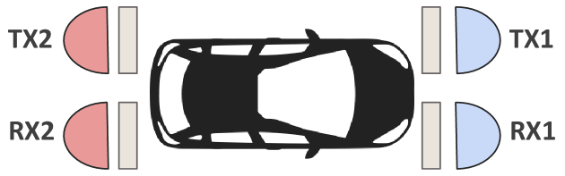
Our scenario consists of a set of vehicles moving at a constant speed in an urban environment. Each vehicle is equipped with two transmitting antennas (TX1 and TX2) and two receiving antennas (RX1 and RX2), where TX1 and RX1 point forward, and TX2 and RX2 point backward, as illustrated in Fig. 1. Each transmit (receive) antenna is a Uniform Linear Array (ULA) with () elements.
Based on the channel matrix , which represents the channel between transmitter and receiver , we can derive the optimal beamforming vector at the transmitter that maximizes the received Signal to Interference plus Noise Ratio (SINR). This vector is selected within a set of codewords (i.e., the codebook) that depends on , i.e.,
| (1) |
where denotes the transmitter codebook. On the other hand, we assume that the receiver points its beam in the boresight direction using beamforming vector .
As described in Sec. III-A, vehicles can sense the channel and receive SCI to reduce the probability of collision by avoiding selecting resources already reserved by other transmitters. Then, vehicle receives SCI using codeword , i.e.,
| (2) |
where denotes the steering directions on the azimuth plane () and on the elevation plane () of the beamforming vector . Thus, if the transmitter codebook and the receiver codebook are the same (i.e., ), vehicle selects the same codeword for both data transmission and sensing (i.e., ).
We can evaluate the probability of collision as the probability that two or more pairs of nodes select the same resources for transmission. For each transmission from vehicle to vehicle , we define the set of transmitter-receiver pairs that share the same resources as . The SINR between transmitter and receiver at distance is given by
| (3) |
where is the Boltzmann constant, is the noise temperature, is the channel bandwidth, is the channel matrix, and are the optimal beamforming vectors of the transmitters (both intended and interfering, respectively), and is the beamforming vector of the intended receiver. The expression in Eq. 3 accounts for the interference due to concurrent transmissions from vehicle to vehicle , which overlap with the intended transmission from to . Then, vehicles and are in coverage and can successfully receive and decode data transmissions if , where is the SINR threshold.
II-B Transmission Model
The SCI is transmitted over the PSCCH, and can be decoded by sensing the channel [4]. As described in Sec. III-A, SCI is used to select resources, i.e., Physical Resource Blocks (PRBs), to be used for data transmissions over the PSSCH. From [14], a PRB consists of subcarriers in frequency and Orthogonal Frequency Division Multiplexing (OFDM) symbols in time, i.e., in a slot (excluding Automatic Gain Control (AGC) symbol and a guard symbol). Overall, a group of PRBs create a subchannel, and there are consecutive subchannels in the available bandwidth. Now, the number of Resource Elements (REs) allocated for transmission per slot, i.e., excluding PRBs used for control, is:
| (4) |
where is the number of REs allocated to the DeModulation Reference Signal (DMRS) for channel estimation, and is the number of PRBs used for PSCCH. Based on Eq. 4, the number of bits per slot that can be allocated for transmission () is
| (5) |
where is the code rate, is the modulation order, is the number of layers, and is the overhead for the 2nd-stage SCI, which is transmitted over the PSSCH [4].
III Resource Allocation in NR V2X
In this section we describe resource allocation (Sec. III-A) and directional beamformed resource allocation (Sec. III-B) in NR V2X.
III-A Resource Allocation in NR V2X Mode 2
The NR V2X standard defines two resource allocation modes (namely Mode 1 and Mode 2) for V2X sidelink communication [15]. In Mode 1 (similar to Mode 3 in Long Term Evolution (LTE) V2X), the selection of the resources is coordinated by a Next Generation Node B (gNB), which reduces the probability of collision but requires vehicles to be in coverage of a cellular infrastructure. In Mode 2 (similar to Mode 4 in LTE V2X), vehicles can autonomously select their sidelink resources without the coordination of a gNB, which permits network operations without coverage. Mode 2 supports both dynamic and Semi Persistent Scheduling (SPS), with the latter reserving resources for multiple consecutive transmissions.
In NR V2X Mode 2 SPS, each vehicle reserves resources for data transmissions for a number of consecutive Transport Blocks (TBs) given by the Reselection Counter (RC). The RC is based on the value of the Resource Reservation Interval (RRI): if RRI ms, the RC is randomly selected within the interval , where ; if RRI ms, the RC is randomly selected within the interval [16]. We define two quantities:
-
•
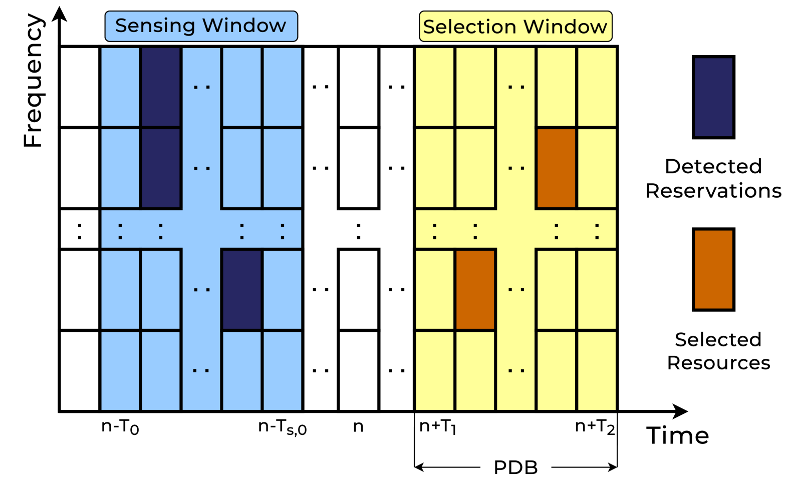
The “Sensing Window,” i.e., the set of channel resources (in the time and frequency domains) that the vehicle “senses,” i.e., listens to. In this phase, each vehicle receives the 1st-stage SCI, transmitted by other vehicles in the Sensing Window resources. Specifically, it indicates the sidelink resources that other vehicles have reserved for their SCI and TB transmissions in the PSCCH and PSSCH, respectively.
-
•
The “Selection Window,” i.e., the set of candidate (not reserved) time and frequency resources that may be used for transmission. The Selection Window is identified based on the Sensing Window, which is derived from the decoded 1st-stage SCI and its RSRP, measuring the quality of the signal.
III-B Directional Beamformed Resource Allocation
Resource allocation in NR V2X Mode 2 as explained in Sec. III-A does not consider directionality and spatial diversity while selecting resources, which is essential in FR2. In particular, resource allocation is based on the assumption that vehicles can sense the channel via omnidirectional communication, which permits to receive SCI from most neighbors, thus reducing the probability of collision. In FR2, instead, it may be essential to establish directional communication even for SCI transmissions, in order to compensate for the higher path loss at these frequencies, and extend the range via beamforming. Directional communication, however, requires precise alignment of the transmitting and receiving beams, and may suffer from the hidden node problem since a vehicle can only receive SCI if it is within the direction of the transmitter. To address these challenges, we define a directional beamformed resource allocation (DBRA) scheme for NR V2X that takes into account the directionality and spatial diversity introduced by using antenna arrays for beamforming in FR2. We define the following procedure, also illustrated in Figs. 3 and 2.
-
•
Definition of the Sensing Window: At slot , the Sensing Window is defined in the range , where is a preconfigured integer, equivalent to ms or ms in number of slots, and is the sensing processing time in number of slots [7]. Ideally, exhaustive search should be used to receive the SCI through a predefined codebook of directions covering the entire angular space [17]. However, this approach would introduce a large delay required to sweep all possible directions during the sensing procedure. Additionally, it could intensify the exposed node problem by detecting resources that would not cause interference. Therefore, we restrict SCI transmission to two specific directions, as opposed to omnidirectional sensing in baseline NR V2X Mode 2. These directions are the “primary direction,” determined based on the receiver’s location, and the “paired direction,” which is the opposite of the primary. The received SCI is used to identify the set of resources that cannot be selected for subsequent transmissions. Specifically, resources are marked as “reserved” if the relative RSRP is higher than a threshold, meaning that there might be other concurrent transmissions in those resources.
-
•
Definition of the Selection Window: The Selection Window is defined in the range , where is the number of slots required for selecting resources, and is less than or equal to the Packet Delay Budget (PDB) in slots to ensure timely transmission. In fact, the PDB is determined by the V2X application, and refers to the latency deadline by which TBs must be transmitted [18]. The PDB is critical in NR V2X to ensure timely delivery of data, especially for safety-related applications. As the PDB increases, we can extend the length of the Selection Window, so the set of available resources for transmission. Within the Selection Window, the vehicle randomly selects a set of free resources (slots) based on the Sensing Window, where is the size of the data to send, and is given in Eq. 5.
-
•
As described in Sec. III-A, resources are selected for a number of consecutive TBs given by the RC, which is specific to each receiver. At each transmission, the RC is decreased by 1. When it reaches 0, the same set of resources is selected with probability , while with probability a new Sensing Window is defined to select a new set of resources.
| Parameter | Symbol | Value |
| OFDM symbols per slot | 12 | |
| Subcarriers per PRB | 12 | |
| REs for DMRS | 18 | |
| PRBs per subchannel | 25 | |
| Number of subchannels | {1, 2, 3, 4} | |
| PRBs used for PSCCH | 50 | |
| 2nd-stage SCI overhead [Bits] | 48 | |
| Code rate | 0.7 | |
| Modulation order | 6 | |
| Number of layers | 1 | |
| Resource Reservation Interval [ms] | RRI | 100 |
| Application rate [Mbps] | {5.7, 20, 40} | |
| TX antenna elements | {4, 16, 64} | |
| RX antenna elements | 2 | |
| Total bandwidth [MHz] | 400 | |
| Transmit power [dBm] | 23 | |
| Noise temperature [K] | 300 | |
| SNR threshold [dB] | 0 | |
| Resource reuse probability | 0 | |
| Available resources [%] | 20 | |
| Carrier frequency [GHz] | 60 |
IV Performance Evaluation
IV-A Simulation Parameters
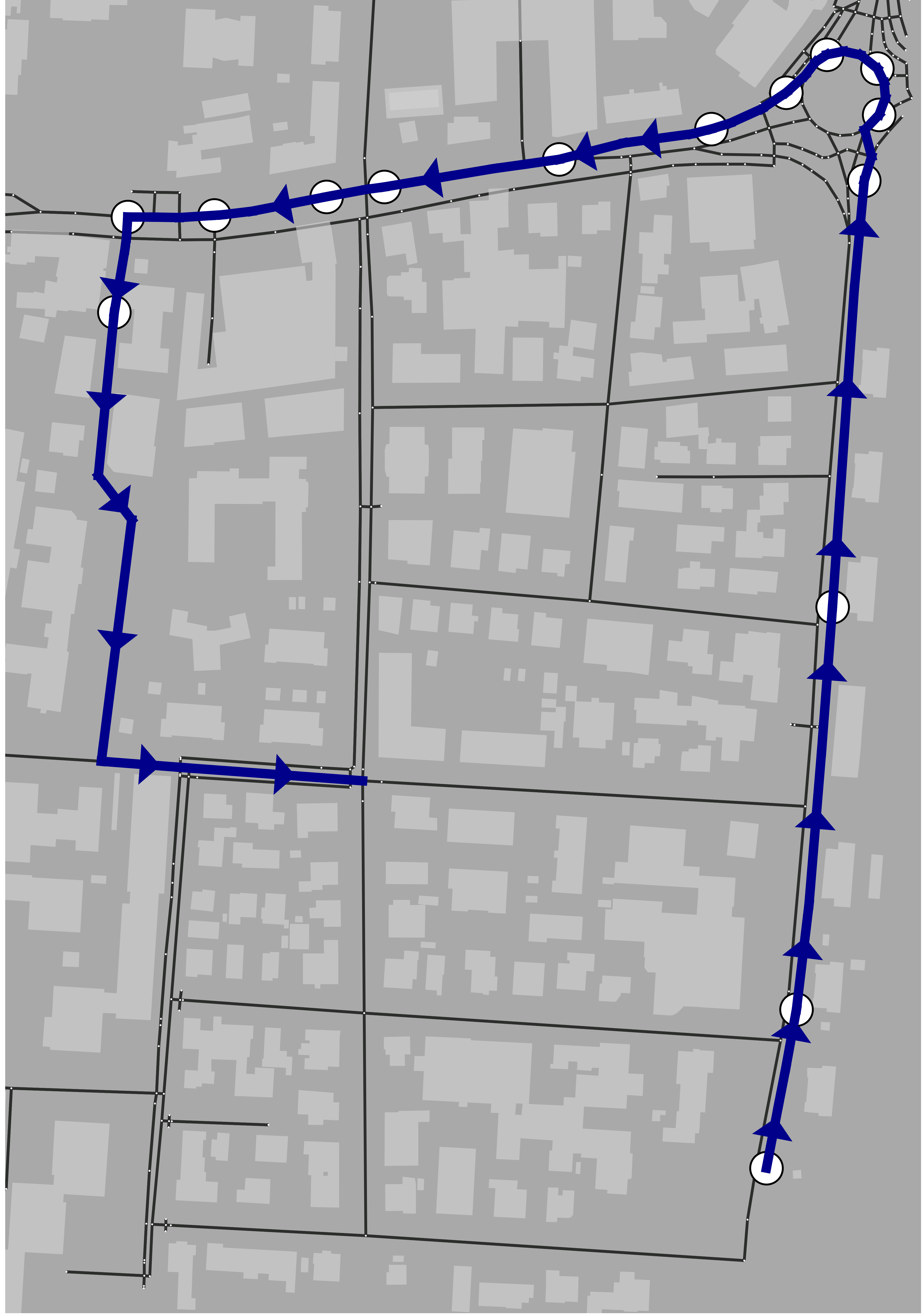
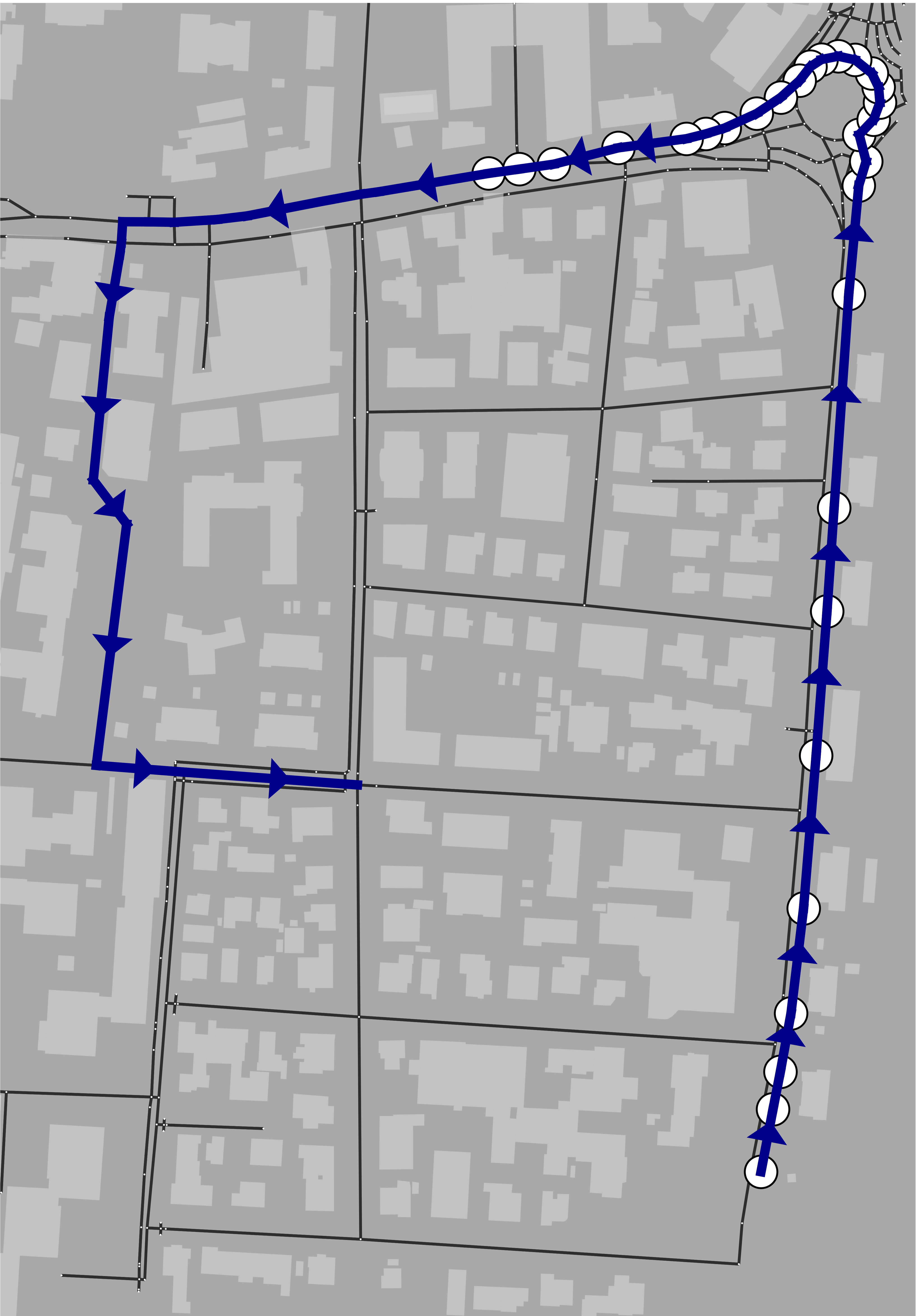
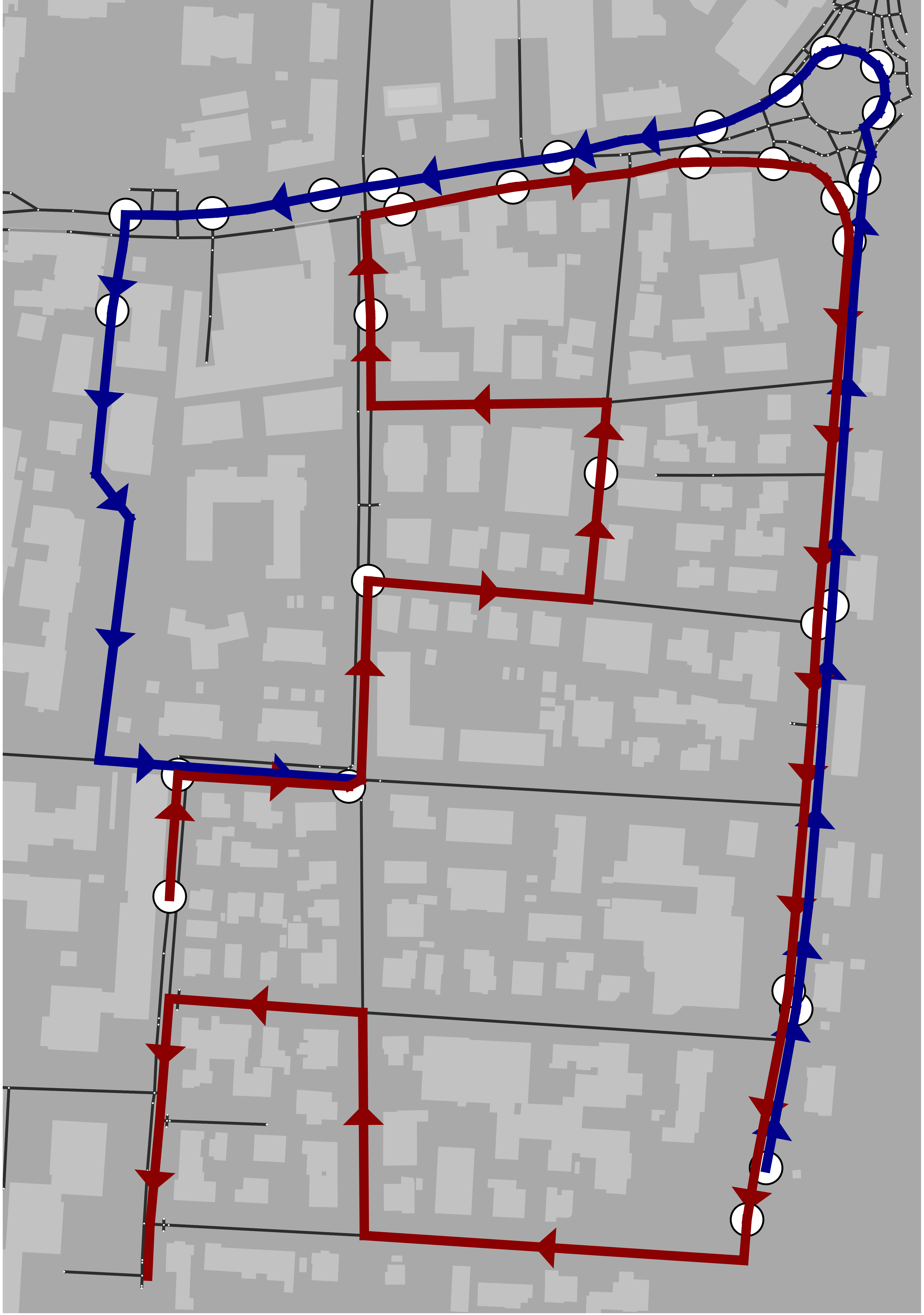
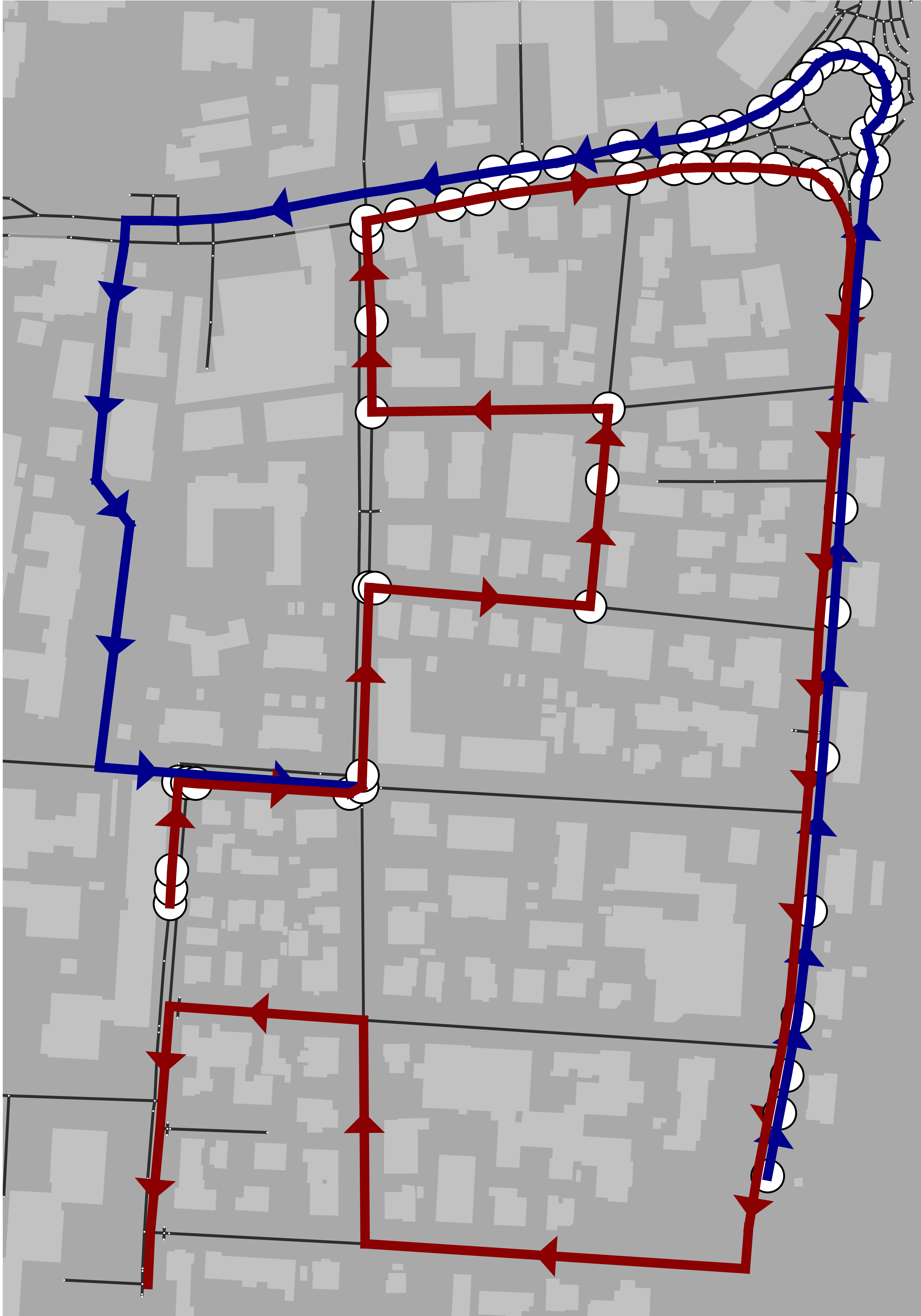
The simulation scenario is implemented in Python, and the physical layer is designed based on 3GPP Rel-18 specifications for NR V2X. The positions of the vehicles are obtained from OpenStreetMap data, specifically for a small area within the city of Padova, Italy. Vehicles move along the grid, defined by OpenStreetMap, following a constant velocity model, traveling at a fixed speed of 10 m/s. Each vehicle transmits data frames (e.g., generated from onboard sensors) of size Mb at a rate of fps, to up to neighboring vehicles (set to 5 in our simulations), therefore the resulting application rate is Mbps.
We consider V2V communication and SCI transmissions in FR2 in the unlicensed bands at 60 GHz, with a total bandwidth of MHz. The transmit (receive) antenna array is a ULA with () elements. The radiation pattern of both is based on the 3GPP Technical Report in [19].
The rest of the simulation parameters are reported in Table I.
Our simulator implements and uses the NVIDIA Sionna Ray Tracer (RT) to compute the channel and characterize the propagation of the signal [20]. This RT is Graphics Processing Unit (GPU) accelerated, which improves the performance in terms of speed and scalability. For each pair of vehicles, we compute the channel matrix using Sionna, and derive the optimal beamforming vector to maximize the SINR, as described in Sec. II-A.
We analyze four different scenarios in an urban environment, as illustrated in Fig. 4:
- •
- •
Table II reports the statistics (number of vehicles, and average and standard deviation of the distance between pairs of vehicles) for the considered urban scenarios. As expected, as the number of vehicles increases, the average distance and variance decrease accordingly.
Additionally, we explored four different Physical Resource Frame Structure (PRFS) configurations:
-
•
PRFS-1: Numerology with .
-
•
PRFS-2: Numerology with .
-
•
PRFS-3: Numerology with .
-
•
PRFS-4: Numerology with .
Notably, is a function of the numerology. As the numerology decreases, with fixed bandwidth, the slot duration increases (from 31.25 s for numerology 6 to 125 s for numerology 3 [14]), so the number of slots in the time domain decreases. As a result, more subchannels are required in the frequency domain to compensate this condition, and maintain the same total number of resources (from for numerology 6 to for numerology 3).
We compare the following resource allocation schemes:
-
•
DBRA: It is the directional beamformed resource allocation scheme presented in Sec. III-B, where SCI is transmitted in both the primary and paired directions.
-
•
DBRA-O: It is the same as DBRA, but SCI is transmitted only in the primary direction to reduce interference.
-
•
RRA (benchmark): Resources are selected randomly in the Selection Window.
Each scheme requires a specific number of resources to be allocated for SCI transmissions, as reported in Table III.
IV-B Simulation Results
| Scenario | Vehicles | Avg. distance [m] | Std. dev. distance [m] |
|---|---|---|---|
| 1W-LD | 15 | 54.2 | 42.0 |
| 1W-HD | 30 | 19.2 | 17.4 |
| 2W-LD | 30 | 64.5 | 42.1 |
| 2W-HD | 60 | 21.0 | 19.7 |
| Scheme | Primary Direction | Paired Direction |
|---|---|---|
| DBRA | 12 PRBs + 48 bits | 12 PRBs |
| DBRA-O | 12 PRBs | N/A |
| RRA | N/A | N/A |
In the following results, we assume that each vehicle can communicate with neighbors. Fig. 5 shows the boxplot of the SINR for the three resource allocation schemes. We observe that DBRA consistently outperforms its competitors in terms of both median and minimum SINR. In fact, DBRA can sense SCI in both primary and paired directions, thereby improving resource selection. As expected, as increases, the SINR also increases given the higher beamforming gain.
As far as the antenna configuration is concerned, in Fig. 6 we observe that the collision probability decreases as increases: for instance, in the 2W-HD scenario, it is approximately 13% for vs. 7% for for DBRA. On one side, configures larger beams and the vehicles can receive more SCI transmissions, reducing the exposed node problem and resulting in better resource allocation. On the other side, provides more spatial diversity by beamforming, which also improves the SINR. Overall, the latter is the dominant component, which demonstrates that directional resource allocation is feasible and convenient in NR V2X. In general, DBRA outperforms DBRA-O given that more SCI transmissions are received: in the 1W-HD scenario and for , the collision probability goes from 11% to almost 15%, respectively. Notice that the collision probability is higher in 2W-HD and 1W-HD compared to 2W-LD and 1W-LD since the network is more congested (i.e., there are more vehicles).
Since the trends for the average collision probability in the different scenarios are similar, we focus on the 1W-HD scenario for the remainder of our evaluation. Fig. 7 illustrates the average collision probability as a function of the PRFS configuration and the application rate. We observe that the collision performance improves as PRFS decreases for all resource allocation schemes, and it is up to 25% for PRFS-4 and Mbps. As the numerology decreases, the PRB size also decreases, which effectively reduces the number of resources that need to be allocated for sending data. As such, the system configures fewer transmissions, so the collision probability decreases. At the same time, with a smaller (narrower) PRB, the impact of thermal noise is less significant, which improves the SINR and further demonstrates the lower collision probability as PRFS decreases.
Another important observation is that, as the application rate increases, the average collision probability also increases. This is because vehicles are required to use more resources (i.e., select more PRBs in the Selection Window) to transmit data within the PDB. Interestingly, as increases, the benefits of DBRA with respect to its competitors are less evident since vehicles tend to use all the available resources, regardless of the optimization approach. When and Mbps, the total number of available resources is likely higher than the number of resources to be allocated for sending data, so we can optimize the selection of the available resources based on the SCI: for DBRA, the collision probability is up to 50% and 70% lower than DBRA-O and RRA, respectively. In contrast, for Mbps the system is close to the saturation point, and the collision probability becomes comparable in all schemes. For example, for PRFS-1, according to Eq. 5, and we have 80 slots of s within a 10-ms PDB. Then, for ( Mb), we need at least slots for data transmission, which is only 15% of the available resources. For Mbps ( Mb), we have , meaning that 100% of the resources are consumed.
Now, we consider another scenario where each vehicle only communicates with one receiver (i.e., ). In Fig. 8 we evaluate the impact of the PDB and the antenna array size when Mbps. Notably, as the PDB decreases, the collision probability of RRA improves, while for DBRA it is the opposite. This is due to the fact that, as we set more critical latency constraints, the total number of resources in the Selection Window decreases, and vehicles may be required to use most of the resources to satisfy the PDB requirement, regardless of the available SCI. Consequently, DBRA tends to approximate RRA.
V Conclusions
In this work, we explored uncoordinated resource allocation for NR V2X Mode 2 in the 60 GHz unlicensed bands. In this scheme, vehicles independently select resources for transmission from a predefined pool, using the SCI received from their neighbors to facilitate this selection. Specifically, the SCI is used to identify the available resources, and reduce the probability of collision. While NR V2X assumes omnidirectional sensing, we considered directional beamforming for both data and SCI transmissions. We evaluated the performance of this approach via simulations as a function of the density of vehicles, the PRFS, the antenna array size, and the PDB. We demonstrated that directional resource allocation via SCI can actually reduce the probability of collision compared to some benchmark schemes.
As part of our future work, we will consider the impact of mobility, as well as errors in the estimate of the position of the vehicles. Moreover, we will formulate an analytical model for the collision probability to validate our simulation results.
References
- [1] A. Gohar and G. Nencioni, “The role of 5G technologies in a smart city: The case for intelligent transportation system,” Sustainability, vol. 13, no. 9, p. 5188, May 2021.
- [2] D. Kombate et al., “The Internet of vehicles based on 5G communications,” in IEEE International Conference on Internet of Things (iThings) and IEEE Green Computing and Communications (GreenCom) and IEEE Cyber, Physical and Social Computing (CPSCom) and IEEE Smart Data (SmartData), 2016.
- [3] T. Zugno, M. Drago, M. Giordani, M. Polese, and M. Zorzi, “Toward standardization of millimeter-wave vehicle-to-vehicle networks: Open challenges and performance evaluation,” IEEE Communications Magazine, vol. 58, no. 9, pp. 79–85, Sep. 2020.
- [4] S.-Y. Lien et al., “3GPP NR sidelink transmissions toward 5G V2X,” IEEE Access, vol. 8, pp. 35 368–35 382, Feb. 2020.
- [5] K. Matrouk, Y. Trabelsi, V. Gomathy, U. A. Kumar, C. Rathish, and P. Parthasarathy, “Energy efficient data transmission in intelligent transportation system (ITS): Millimeter (mm wave) based routing algorithm for connected vehicles,” Optik, vol. 273, p. 170374, Feb. 2023.
- [6] I. Rasheed, F. Hu, Y.-K. Hong, and B. Balasubramanian, “Intelligent vehicle network routing with adaptive 3D beam alignment for mmWave 5G-based V2X communications,” IEEE Transactions on Intelligent Transportation Systems, vol. 22, no. 5, pp. 2706–2718, May 2020.
- [7] M. H. C. Garcia et al., “A Tutorial on 5G NR V2X Communications,” IEEE Communications Surveys & Tutorials, vol. 23, no. 3, pp. 1972–2026, Thirdquarter 2021.
- [8] 3GPP, “NR; Physical layer measurements (Release 18),” TS 38.215, 2024.
- [9] P. Tarafder and W. Choi, “MAC protocols for mmWave communication: A comparative survey,” Sensors, vol. 22, no. 10, p. 3853, May 2022.
- [10] M. Giordani, A. Zanella, and M. Zorzi, “Millimeter wave communication in vehicular networks: Challenges and opportunities,” in 6th International Conference on Modern Circuits and Systems Technologies (MOCAST), May 2017.
- [11] M. S. Bahbahani, E. Alsusa, and A. Hammadi, “A directional TDMA protocol for high throughput URLLC in mmWave vehicular networks,” IEEE Transactions on Vehicular Technology, vol. 72, no. 3, pp. 3584–3599, Mar. 2022.
- [12] L. Su et al., “Content distribution based on joint V2I and V2V scheduling in mmWave vehicular networks,” IEEE Transactions on Vehicular Technology, vol. 71, no. 3, pp. 3201–3213, Mar. 2022.
- [13] T. Higuchi, M. Giordani, A. Zanella, M. Zorzi, and O. Altintas, “Value-anticipating V2V communications for cooperative perception,” in IEEE Intelligent Vehicles Symposium (IV), 2019.
- [14] 3GPP, “NR; Physical layer procedure for data (Release 18),” TS 38.214, 2024.
- [15] ——, “Study on NR vehicle-to-everything (V2X) (Release 16),” TR 38.885, 2019.
- [16] L. Lusvarghi, A. Molina-Galan, B. Coll-Perales, J. Gozalvez, and M. L. Merani, “A comparative analysis of the semi-persistent and dynamic scheduling schemes in NR-V2X mode 2,” Vehicular Communications, vol. 42, p. 100628, Aug. 2023.
- [17] M. Giordani, M. Polese, A. Roy, D. Castor, and M. Zorzi, “A tutorial on beam management for 3GPP NR at mmWave frequencies,” IEEE Communications Surveys & Tutorials, vol. 21, no. 1, pp. 173–196, Firstquarter 2018.
- [18] A. Molina-Galan, L. Lusvarghi, B. Coll-Perales, J. Gozalvez, and M. L. Merani, “On the Impact of Re-evaluation in 5G NR V2X Mode 2,” IEEE Transactions on Vehicular Technology, Feb. 2023.
- [19] 3GPP, “Study on channel model for frequencies from 0.5 to 100 GHz (Release 14),” TR 38.901, 2018.
- [20] J. Hoydis et al., “Sionna: An Open-Source Library for Next-Generation Physical Layer Research,” arXiv preprint arXiv:2203.11854, Mar. 2022. [Online]. Available: https://arxiv.org/abs/2203.11854