ChatStitch: Visualizing Through Structures via Surround-View Unsupervised Deep Image Stitching with Collaborative LLM-Agents
Abstract
Collaborative perception has garnered significant attention for its ability to enhance the perception capabilities of individual vehicles through the exchange of information with surrounding vehicle-agents. However, existing collaborative perception systems are limited by inefficiencies in user interaction and the challenge of multi-camera photorealistic visualization. To address these challenges, this paper introduces ChatStitch, the first collaborative perception system capable of unveiling obscured blind spot information through natural language commands integrated with external digital assets. To adeptly handle complex or abstract commands, ChatStitch employs a multi-agent collaborative framework based on Large Language Models. For achieving the most intuitive perception for humans, ChatStitch proposes SV-UDIS, the first surround-view unsupervised deep image stitching method under the non-global-overlapping condition. We conducted extensive experiments on the UDIS-D, MCOV-SLAM open datasets, and our real-world dataset. Specifically, our SV-UDIS method achieves state-of-the-art performance on the UDIS-D111we extract a subset of data from the original UDIS-D dataset for the multi-image stitching experiment. dataset for 3, 4, and 5 image stitching tasks, with PSNR improvements of 9%, 17%, and 21%, and SSIM improvements of 8%, 18%, and 26%, respectively.
I Introduction
Perception plays a crucial role in intelligent unmanned systems, where its primary goal is to extract pertinent information from the surrounding environment and convey it to subsequent tasks such as mapping, planning, and control. With the continuous advancements in deep learning, individual perception has made significant strides across various perception tasks, including image stitching[1, 2, 3, 4], object detection[5, 6, 7, 8], and semantic segmentation[9, 10, 11, 12]. Despite the immense potential exhibited by individual perception, this approach often encounters issues such as occlusions, primarily due to the limited viewpoint of a single agent. To address this challenge, collaborative perception[13] has garnered widespread attention from both the academic and industrial communities in recent years. The objective of collaborative perception is to enhance the perception capabilities of individual vehicles by exchanging complementary information with surrounding agents.
Recent efforts have made valuable contributions both in the development of high-quality real or simulated datasets and in devising effective solutions to realize collaborative perception[14, 15, 16, 17, 18]. However, existing collaborative perception approaches predominantly focus on the exchange of information between agents, with a notable absence of human involvement. On one hand, current collaborative schemes lack responsiveness to human directives[19, 20, 21]; on the other hand, these approaches primarily concentrate on enhancing the effectiveness of perception tasks[22, 23, 24], such as object detection, and often overlook the direct intuitive experiences of humans in photo-realistic environments.
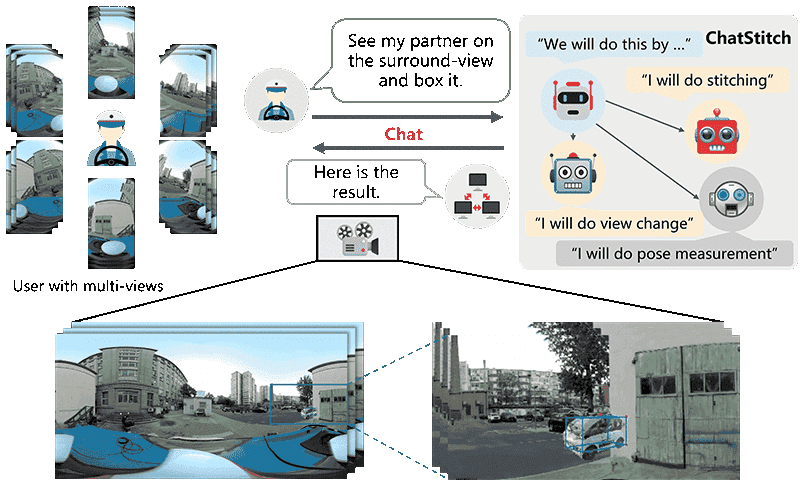
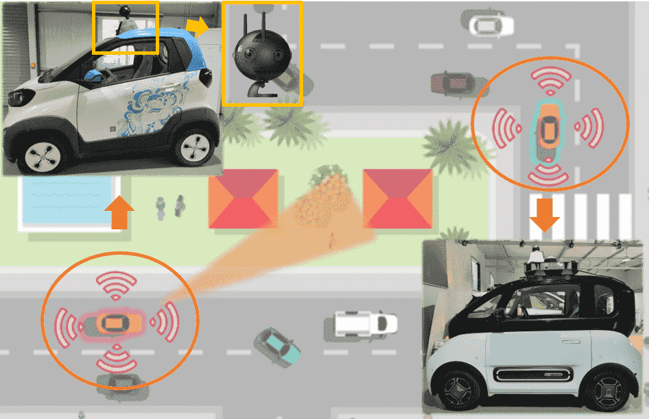
To address these needs, we introduce ChatStitch, the first collaborative perception system capable of revealing obscured blind spot information through natural language commands integrated with external digital assets. To utilize ChatStitch, users simply engage in dialogue with the system, issuing commands in natural language without the need to partake in the intermediate perception steps. This process is illustrated in Fig. 1.
To adeptly handle complex or abstract commands, ChatStitch employs a multi-agent collaborative framework based on Large Language Models (LLMs). The core concept revolves around utilizing multiple LLM-agents, each designated with a specific role, to decompose the overall collaborative perception requirements into distinct tasks. This reflects the functional segmentation typically established within technological frameworks. This workflow offers two primary advantages. Firstly, the Large Language Models are capable of processing human natural language commands, allowing for intuitive and dynamic adjustments to the collaborative perception displays, thereby achieving precise tuning and feedback. Secondly, the collaborative framework enhances the effectiveness and accuracy of collaborative perception by allocating specific tasks among specialized agents, thus expanding the boundaries of collaborative perception capabilities.

To achieve the most intuitive perception for humans, we propose SV-UDIS in ChatStitch, which stitches multiple surround view images in driving scenarios into a panoramic image. The current state-of-the-art (SoTA) unsupervised image stitching algorithms[3, 25] mainly focus on two-image stitching tasks. Although they can also perform multi-image stitching, they are not suitable for surround view images in driving scenarios. On one hand, in these scenarios, the overlapping areas between the images to be stitched are extremely small, resulting in severe stretching at the edges of the warped images. On the other hand, only adjacent images have overlapping areas, so there is no common reference image that has shared view areas with all other images, as shown in Fig. 2(b). For clarity, we define the above surround-view stitching task as a multi-image stitching problem under the non-global-overlapping condition. A detailed definition of this problem can be found in Section IV-A; more discussion on multi-image stitching please refer to our supplementary materials. Our proposed SV-UDIS method, through masked cylindrical projection, rectangular warping constraints, and motion propagation, achieves multi-image stitching under the non-global overlapping condition, providing humans with intuitive visual effects.
To demonstrate the visual advantages of collaborative perception in intuitive scenarios such as occluded buildings, we conducted experiments on UDIS-D[2] dataset; MCOV-SLAM[26] dataset and our real-world dataset. The results indicate that ChatStitch can generate photorealistic collaborative perception outcomes through occluded buildings responding to a variety of human language commands.Our proposed SV-UDIS achieves SoTA performance on the UDIS-D dataset for 3, 4, and 5 image stitching tasks, with PSNR improvements of 9, 17, and 21, and SSIM improvements of 8, 18, and 26, respectively.
In brief, we have made the following contributions:
-
•
We develop an innovative framework, named ChatStitch, which is the first collaborative perception system capable of unveiling obscured blind spot information through natural language commands integrated with external digital assets.
-
•
We propose SV-UDIS, the first surround-view unsupervised deep image stitching framework under the non-global-overlapping condition, which stitches common surround images in driving scenarios into a panorama, providing intuitive visual effects.
-
•
We achieved photorealistic perspective effects in challenging scenarios, like occluded buildings, on both public and real-world datasets. Our method achieves SoTA performance on UDIS-D and MOCV-SLAM open datasets, resulting in a significant improvement in performance.
| Method # |
|
Dim. |
|
Editable |
|
Language |
|
Stitching | ||||||||
| AirSim[27] | \usym2613 | 3D | \usym1F5F8 | \usym1F5F8 | \usym1F5F8 | \usym2613 | \usym1F5F8 | \usym2613 | ||||||||
| OpenScenario[28] | \usym2613 | 3D | \usym1F5F8 | \usym1F5F8 | \usym1F5F8 | \usym2613 | \usym1F5F8 | \usym2613 | ||||||||
| 51Sim-One[29] | \usym2613 | 3D | \usym1F5F8 | \usym1F5F8 | \usym1F5F8 | \usym2613 | \usym2613 | \usym2613 | ||||||||
| Who2com[30] | \usym2613 | 3D | \usym1F5F8 | \usym1F5F8 | \usym1F5F8 | \usym2613 | \usym2613 | \usym2613 | ||||||||
| When2com[31] | \usym2613 | 3D | \usym1F5F8 | \usym1F5F8 | \usym1F5F8 | \usym2613 | \usym1F5F8 | \usym2613 | ||||||||
| MP-Pose[32] | \usym2613 | 3D | \usym1F5F8 | \usym1F5F8 | \usym1F5F8 | \usym2613 | \usym2613 | \usym2613 | ||||||||
| CoBEVT[33] | \usym2613 | 3D | \usym1F5F8 | \usym1F5F8 | \usym1F5F8 | \usym2613 | \usym1F5F8 | \usym2613 | ||||||||
| CoCa3D[22] | \usym2613 | 3D | \usym1F5F8 | \usym1F5F8 | \usym1F5F8 | \usym2613 | \usym1F5F8 | \usym2613 | ||||||||
| VIMI[23] | \usym2613 | 3D | \usym1F5F8 | \usym1F5F8 | \usym1F5F8 | \usym2613 | \usym2613 | \usym2613 | ||||||||
| HM-ViT[34] | \usym2613 | 3D | \usym1F5F8 | \usym1F5F8 | \usym1F5F8 | \usym2613 | \usym2613 | \usym2613 | ||||||||
| P-CNN[35] | \usym1F5F8 | 2D | \usym1F5F8 | \usym2613 | \usym2613 | \usym2613 | \usym2613 | \usym2613 | ||||||||
| BEVGen[19] | \usym1F5F8 | 2D | \usym1F5F8 | \usym1F5F8 | \usym2613 | \usym2613 | \usym1F5F8 | \usym2613 | ||||||||
| BEVControl[20] | \usym1F5F8 | 2D | \usym1F5F8 | \usym1F5F8 | \usym2613 | \usym2613 | \usym2613 | \usym2613 | ||||||||
| DriveDreamer[36] | \usym1F5F8 | 2D | \usym1F5F8 | \usym1F5F8 | \usym2613 | \usym1F5F8 | \usym2613 | \usym2613 | ||||||||
| DrivingDiffusion[37] | \usym1F5F8 | 2D | \usym1F5F8 | \usym1F5F8 | \usym2613 | \usym1F5F8 | \usym2613 | \usym2613 | ||||||||
| P2OD[38] | \usym1F5F8 | 2D | \usym1F5F8 | \usym2613 | \usym2613 | \usym2613 | \usym2613 | \usym2613 | ||||||||
| MagicDrive[39] | \usym1F5F8 | 2D | \usym1F5F8 | \usym1F5F8 | \usym2613 | \usym2613 | \usym2613 | \usym2613 | ||||||||
| UniSim[21] | \usym1F5F8 | 3D | \usym2613 | \usym1F5F8 | \usym2613 | \usym2613 | \usym2613 | \usym2613 | ||||||||
| MARS[40] | \usym1F5F8 | 3D | \usym2613 | \usym1F5F8 | \usym2613 | \usym2613 | \usym1F5F8 | \usym2613 | ||||||||
| ChatSim[24] | \usym1F5F8 | 3D | \usym1F5F8 | \usym1F5F8 | \usym1F5F8 | \usym1F5F8 | \usym1F5F8 | \usym2613 | ||||||||
| ChatStitch(Ours) | \usym1F5F8 | 3D | \usym1F5F8 | \usym1F5F8 | \usym1F5F8 | \usym1F5F8 | \usym1F5F8 | \usym1F5F8 |
II Related work
Collaborative perception. Existing collaborative perception methods are primarily categorized into three main types[41]: Early Collaboration[42, 43, 44], Intermediate Collaboration[31, 45, 46, 33, 22], and Late Collaboration[47, 16]. A comparison of different methods is shown in Table I. However, regardless of the type of collaborative perception method employed, most focus primarily on the interactions between agents and the final task outcomes, lacking human participation and intuitive perception in collaborative perception methods. In our work, Chatstitch, adhering to the philosophy of human-in-the-loop, enables the adjustment and intuitive display of perception tasks through the processing of human natural language.
Unsupervised image stitching. Image stitching technology[48] combines multiple images with overlapping areas to generate an image with a larger field of view. In recent years, learning-based image stitching methods[49] have emerged. Among them, due to the difficulty in obtaining real stitched labels, unsupervised stitching methods[2, 3, 50, 51] represented by UDIS[2] and UDIS2[3] are more popular than supervised methods[52, 53, 54, 55]. However, few have considered multi-image stitching under the non-global-overlapping condition, which is common in driving scenarios, such as the camera configurations used in the NuScenes[56], Waymo[57] and PandaSet[58] datasets, where all images are horizontally arranged with extremely low overlapping areas. In this paper, we propose SV-UDIS, a multi-image stitching algorithm for non-global-overlapping situations.
Large Language Model and multi-agent framework. Large Language Models are designed to integrate vast amounts of data for understanding, generating, and responding to human language. Since Google introduced the Transformer model [59], a plethora of models and methods based on it have emerged, particularly exemplified by the Large Language Models such as GPT[60] and BERT[61]. Building on LLMs, many efforts have begun utilizing rich multi-agent collaborative pattern components[24], enabling agents to function optimally in their respective roles across various domains. In our work, we explore the use of a multi-agent framework to accomplish collaborative perception tasks and to display the intuitive results of such collaboration.
III Multi-Agent Collaborative Framework
ChatStitch analyzes complex and abstract commands in human-machine collaboration, providing users with photorealistic collaborative perception visualization videos. Please refer to Fig. 3. The challenge of directly applying a single LLM-agent lies in its struggle with multistep reasoning and cross-referencing [24]. Drawing from this insight, we employ a multi-agent collaborative framework with LLM agents, where each agent is responsible for managing a specific module of the collaborative perception task.
III-A Agents’ Functionality
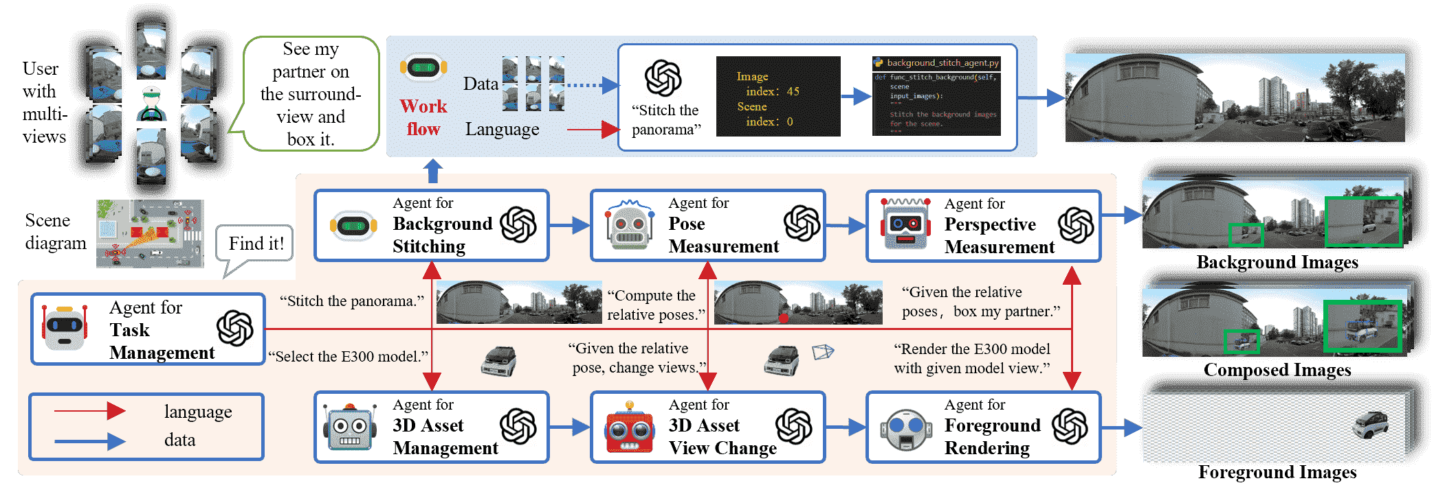
In our framework, agents have two primary functions: On one hand, they receive concise, individual instructions from the Task Management Agent, which have been decomposed from larger tasks, and convert these instructions into corresponding parameters using predefined LLM settings. On the other hand, they input these transformed parameters into specific functions to execute the related operations. In other words, each agent is a composite of a specific LLM and corresponding functional modules. This structure not only allows the agents to process human language instructions but also to perform precise operations accordingly. For an example of how an agent converts parameters, please refer to the supplementary materials.
Task Management Agent. The Task Management Agent converts complex and abstract human commands, expressed in sophisticated language, into multiple concise task statements. This agent’s specialized LLM module is designed to decompose these intricate commands into a combination of specific tasks. The corresponding specific function of this agent then channels these output sentences into relevant agents according to their interrelationships.
Background Stitching Agent. The Background Stitching Agent seamlessly stitches vehicle images into a panoramic view, providing users with a 360° surround visual field. This agent’s dedicated LLM module receives stitching instructions and executes the corresponding specific function. Notably, within this agent, we introduce a novel stitching method SV-UDIS, which addresses the issue of multi-image stitching under the non-global-overlapping condition. For detailed information, please refer to Section IV.
Relative Pose Measurement. The Relative Pose Measurement Agent transforms the positions of partners into its own coordinate system and marks them on the panoramic view. This agent’s specialized LLM module receives the IDs and corresponding GPS positions of all vehicles, converting them into the appropriate parameters. Its corresponding specific function then translates the partner positions into its own image coordinate system and marks the respective locations on the panoramic view.
Perspective Measurement. The Perspective Measurement Agent translates 3D partner dimensions into panoramic view representations, marking bounding boxes accordingly. Its specialized LLM module processes vehicle IDs and dimensions, converting them into parameters for perspective transformations. This function maps dimensions onto the image coordinate system, delineating bounding boxes on the panoramic view.
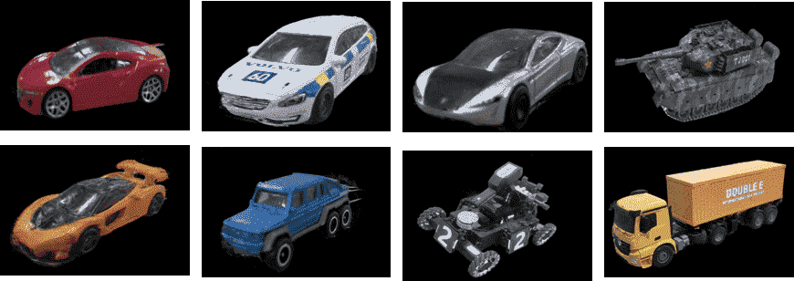
3D Asset Management. The 3D Asset Management Agent selects and manages partner 3D models based on specific instructions. Its LLM module identifies relevant models from the 3D Asset Bank and outputs their IDs, enabling modification and replacement as needed. For a more comprehensive introduction to the 3D Asset Bank, please refer to the supplementary materials.
3D Asset View Change. The 3D Asset View Change Agent determines external view parameters based on partners’ relative positions. Its LLM module processes vehicle IDs and orientations, converting them into parameters. The function then applies coordinate transformations to align with the model’s system and stores the respective viewpoints.
Foreground Rendering. The Foreground Rendering Agent combines viewpoint data and 3D asset information to render partners in a collaborative perception scenario. Its LLM module receives vehicle IDs and activates a specific function, which uses these parameters to call the instant-ngp interface[62] for rendering partners’ images.
III-B Workflow
ChatStich is composed of multiple agents that collaboratively produce panoramic images of a scene based on human instructions. The Task Management Agent breaks down complex human instructions into simpler task directives and delivers them to subsequent other agents. These agents work in two separate processes: Background Stitching and Foreground Rendering.
In the Background Stitching process, the initial step involves stitching images from cameras surrounding the vehicle to create a panoramic view. Subsequently, relative positions and perspective scaling ratios are calculated based on the coordinates of collaborative units, and these are marked on the panoramic image.
In the Foreground Rendering process, the preferred models from the 3D Asset Bank are selected based on prior knowledge. The rendering angles are then calculated based on the poses, and interfaces are called to visually represent the collaborators effectively.
The final images from Foreground Rendering and Background Stitching are integrated to achieve a photo-realistic result for collaborative perception. Thanks to the Task Management Agent’s ability to store instructions and parameters for other agents, it enables scene modifications through multiple rounds of instructions, enhancing dynamic interaction and responsiveness in the scene.
IV SV-UDIS
In this section, we propose SV-UDIS, the first surround-view unsupervised deep image stitching method under the non-global-overlapping condition. we first describe the definition of the non-global-overlapping condition, and then introduce the overall framework of SV-UDIS, as shown in Fig. 4.
IV-A Problem Definition
In this paper, we aim to stitch adjacent images captured by the surround view cameras into a panoramic image, with the camera configuration identical to that of MCOV-SLAM[26]. For a set of surround view image data with the resolution of collected at a certain moment, we define the non-global-overlapping condition (shown in Fig. 2(b)) as: for any image captured by camera , there is and only exists overlapping areas with images captured by adjacent cameras. Represented as:
| (1) |
Similarly, we define the global-overlapping condition (shown in Fig. 2(a)) as: there exists an image , with which all other images have overlapping areas. Represented as:
| (2) |
IV-B Unsupervised Multi-Image Stitching
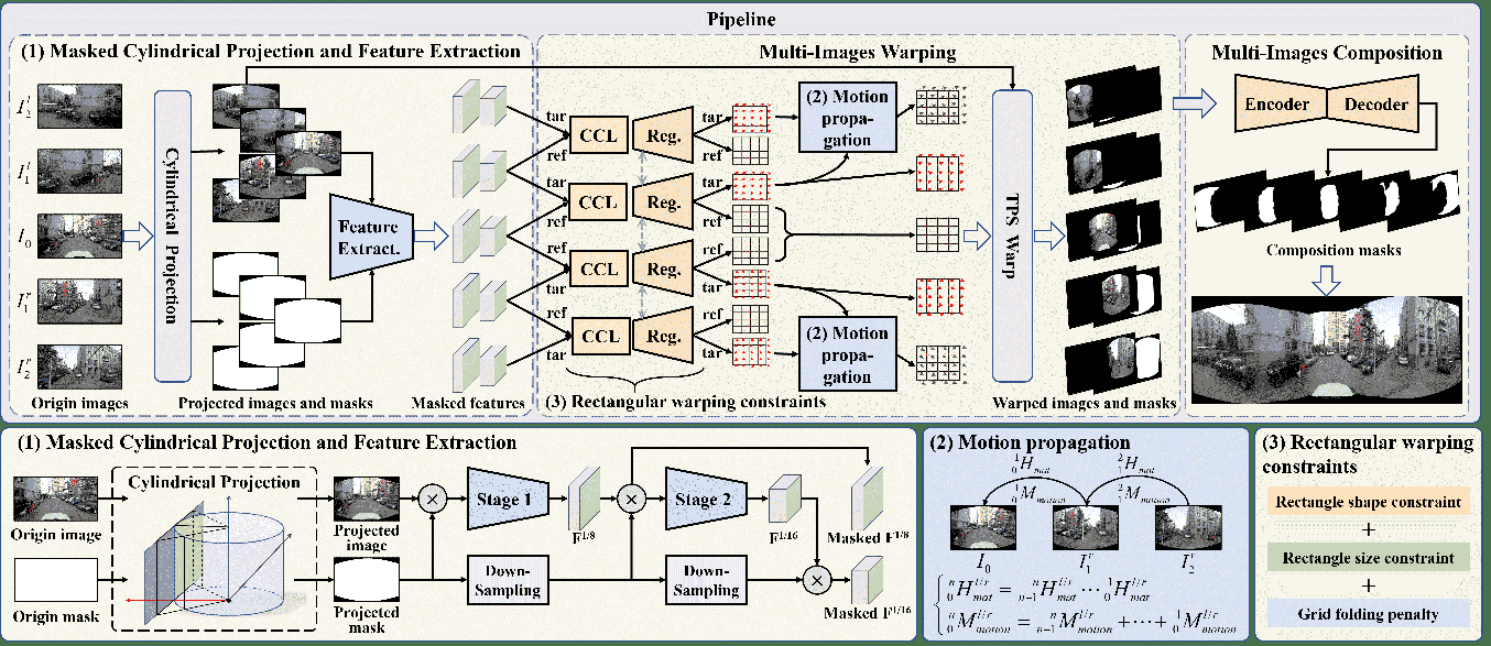
The proposed SV-UDIS framework, as shown in Fig. 4, mainly includes three stages: Masked cylindrical projection and feature extraction, multi-image warping, and multi-image composition. In the first stage, we perform cylindrical projection on the input images, generate projected images and projected masks, and extract multi-scale features. In the second stage, we take two adjacent images as a group, regress their features, and generate the mesh warping of the target image for each group. Then, using our proposed motion propagation strategy, we calculate the mesh motion between the edge image and the central image, thereby generating aligned images and masks through TPS transformation[3]. In the third stage, we predict the image fusion masks through a UNet-like network, thereby generating the final stitched image. A more detailed processing procedure are reported in the supplementary materials.
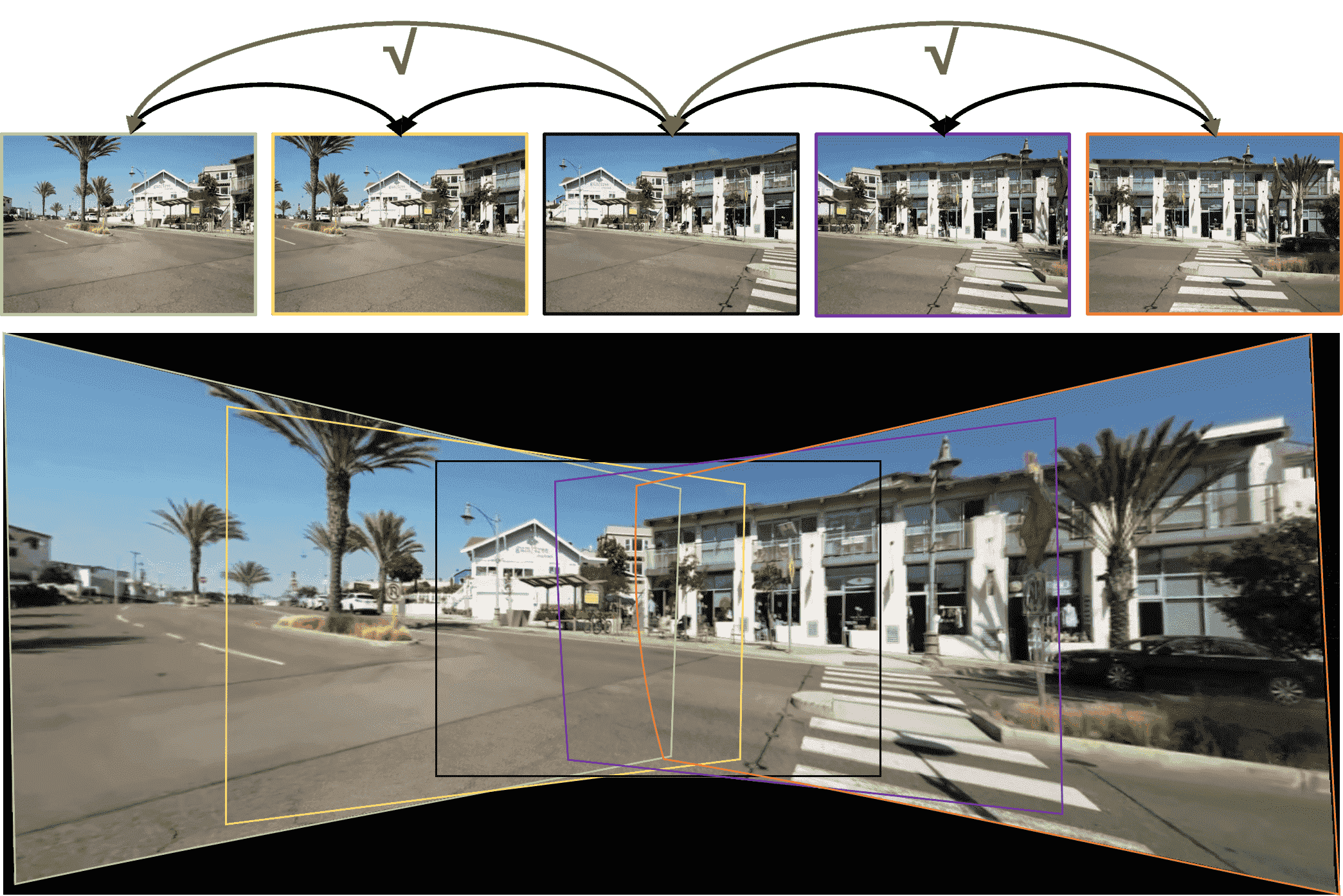
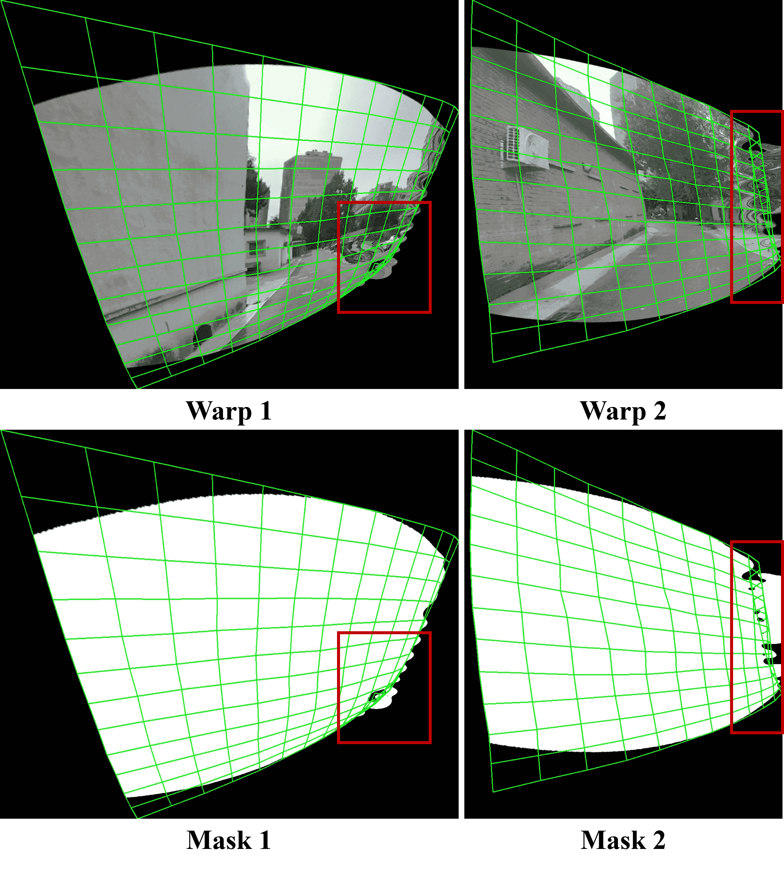
Masked cylindrical projection. In this paper, we aim to stitch multiple images with a large horizontal field of view. To maintain the spatial constraints and visual consistency of the images, we need to process the images with cylindrical projection, i.e., project the images from each camera onto the cylindrical surface, and then unfold the cylindrical surface to achieve the projection deformation of each image. The impact of whether to perform cylindrical projection on the multi-image stitching task with a large horizontal field of view is shown in Fig. 2. A detailed procedure of cylindrical projection can be found in our supplementary material.
After performing cylindrical projection on the input image, we obtain the projected image and its mask. We use ResNet50[63] with pretrained parameters as the backbone network to extract high-dimensional semantic features, and successively obtain feature maps and with resolutions of 1/8 and 1/16 of the original image, respectively. Due to the presence of some black areas in the corners of the projected image, in order to avoid learning these black areas and their contours as significant features, we apply the projected mask during the feature extraction process. As shown in Fig. 4, we finally obtain masked and .
Motion propagation. In the second stage of the process illustrated in Fig. 4, we take two adjacent images as a pair, where the image closer to the center of the field of view serves as the reference image , and the image closer to the edge of the field of view serves as the target image . For each pair of ref-tar images, we use the contextual correlation layer (CCL)[64] to calculate the correlation between feature maps, and then predict the initial motion and the residual motion of the grid control points of the target image through regression networks[3]. For the initial motion, it represents the 4-pt parameterization of the homography warp[65]. We then convert it into a matrix representation , using the normalized Direct Linear Transform (DLT) algorithm. For the residual motion, we divide the target image evenly into a grid of rows and columns, representing the movement of control points.
To stitch all images together to generate a panoramic image, it is necessary to convert the control point motion between adjacent images into global control point motion, that is, to calculate the control point motion of all images relative to the central image. We denote the image in the center of the field of view as , and the images on the left and right sides as and , respectively. Through our motion propagation strategy, the initial homography warp and residual motion of any image on the left or right side relative to the central image can be represented as:
| (3) |
Through the above motion propagation strategy, we can calculate the control point motion of all images relative to the central image, thereby performing globally unified warping and alignment on all images.
| Multi-agent collaboration | language command category | |||
| Show | Unshow | Select | Abstract | |
| 0.704 | 0.211 | 0.368 | 0.462 | |
| ✓ | 0.963 | 0.947 | 0.789 | 0.923 |
| Datasets | Methods | 2 images | 3 images | 4 images | 5 images | |||||||||||||||
| Easy | Moderate | Hard | Average | Easy | Moderate | Hard | Average | Easy | Moderate | Hard | Average | Easy | Moderate | Hard | Average | |||||
|
15.87 | 12.76 | 10.68 | 12.86 | 16.87 | 12.69 | 11.35 | 13.31 | 15.08 | 12.52 | 11.36 | 12.79 | 13.66 | 12.29 | 11.40 | 12.26 | ||||
| UDIS2[3] | 30.19 | 25.84 | 21.57 | 25.43 | 25.18 | 22.11 | 19.12 | 21.66 | 23.21 | 20.84 | 18.20 | 20.36 | 21.53 | 20.15 | 17.57 | 19.46 | ||||
| Ours | 28.79 | 24.57 | 20.71 | 24.28 | 27.69 | 24.05 | 20.60 | 23.58 | 27.66 | 24.04 | 20.93 | 23.77 | 26.89 | 24.34 | 21.30 | 23.62 | ||||
|
12.59 | 11.33 | 10.09 | 11.21 | 12.69 | 11.79 | 10.85 | 11.66 | 12.35 | 11.62 | 10.85 | 11.51 | 12.28 | 11.55 | 10.85 | 11.47 | ||||
| UDIS2[3] | 17.66 | 15.88 | 13.62 | 15.50 | 15.47 | 14.05 | 12.90 | 13.98 | 14.46 | 13.34 | 12.35 | 13.25 | 13.71 | 12.83 | 12.03 | 12.74 | ||||
| Ours | 17.32 | 15.79 | 14.35 | 15.67 | 16.40 | 15.33 | 14.53 | 15.31 | 16.69 | 15.85 | 14.98 | 15.73 | 16.21 | 15.48 | 14.68 | 15.36 | ||||
| Datasets | Methods | 2 images | 3 images | 4 images | 5 images | |||||||||||||||
| Easy | Moderate | Hard | Average | Easy | Moderate | Hard | Average | Easy | Moderate | Hard | Average | Easy | Moderate | Hard | Average | |||||
|
0.530 | 0.286 | 0.146 | 0.303 | 0.572 | 0.273 | 0.157 | 0.310 | 0.459 | 0.258 | 0.157 | 0.275 | 0.355 | 0.252 | 0.164 | 0.241 | ||||
| UDIS2[3] | 0.933 | 0.875 | 0.739 | 0.838 | 0.848 | 0.768 | 0.624 | 0.728 | 0.779 | 0.705 | 0.573 | 0.667 | 0.719 | 0.649 | 0.550 | 0.624 | ||||
| Ours | 0.914 | 0.841 | 0.692 | 0.803 | 0.881 | 0.829 | 0.691 | 0.784 | 0.883 | 0.834 | 0.698 | 0.790 | 0.848 | 0.833 | 0.715 | 0.789 | ||||
|
0.356 | 0.264 | 0.175 | 0.256 | 0.364 | 0.279 | 0.203 | 0.273 | 0.352 | 0.280 | 0.199 | 0.268 | 0.352 | 0.271 | 0.191 | 0.262 | ||||
| UDIS2[3] | 0.709 | 0.629 | 0.476 | 0.591 | 0.566 | 0.503 | 0.401 | 0.479 | 0.514 | 0.444 | 0.355 | 0.427 | 0.488 | 0.411 | 0.337 | 0.401 | ||||
| Ours | 0.751 | 0.694 | 0.555 | 0.655 | 0.688 | 0.634 | 0.595 | 0.634 | 0.700 | 0.656 | 0.621 | 0.655 | 0.673 | 0.624 | 0.577 | 0.619 | ||||
Rectangular warping constraints. Under the non-global-overlapping condition, the overlapping area between adjacent images is usually small. Therefore, the target image warped by the homography matrix often has severe shape stretching at the edges, as shown in Fig. 2. After motion propagation, this shape stretching at the edges is dramatically amplified, resulting in an image with severely irregular edges and scale scaling after stitching.
To mitigate the issue of shape stretching at the edges and to ensure a more natural visual effect in the stitched image, we propose the rectangular warping constraints. The basic idea behind these constraints is that the warped target image should be as close to a rectangle as possible, avoiding severe shape stretching and scale scaling. We design a loss function to implement these constraints, as shown in Eq. 4 , which is composed of three parts: rectangle shape constraint, rectangle size constraint, and grid folding penalty. For the specific meanings and details of each term in the formula, please refer to our supplementary materials.
| (4) |
| Datasets | Methods | PSNR | SSIM | |||||||||
| E | M | H | A | E | M | H | A | |||||
|
15.87 | 12.76 | 10.68 | 12.86 | 0.530 | 0.286 | 0.146 | 0.303 | ||||
| APAP[66] | 27.96 | 24.39 | 20.21 | 23.79 | 0.901 | 0.837 | 0.682 | 0.794 | ||||
| SPW[67] | 26.98 | 22.67 | 16.77 | 21.60 | 0.880 | 0.758 | 0.490 | 0.687 | ||||
| LPC[68] | 26.94 | 22.63 | 19.31 | 22.59 | 0.878 | 0.764 | 0.610 | 0.736 | ||||
| UDIS[2] | 25.16 | 20.96 | 18.36 | 21.17 | 0.834 | 0.669 | 0.495 | 0.648 | ||||
| Ours | 28.79 | 24.57 | 20.71 | 24.28 | 0.914 | 0.841 | 0.692 | 0.803 | ||||
|
12.59 | 11.33 | 10.09 | 11.21 | 0.356 | 0.264 | 0.175 | 0.256 | ||||
| UDIS[2] | 18.03 | 16.17 | 13.37 | 15.60 | 0.674 | 0.561 | 0.320 | 0.498 | ||||
| Ours | 17.32 | 15.80 | 14.35 | 15.67 | 0.751 | 0.694 | 0.555 | 0.655 | ||||
V Experiments
V-A Experimental settings
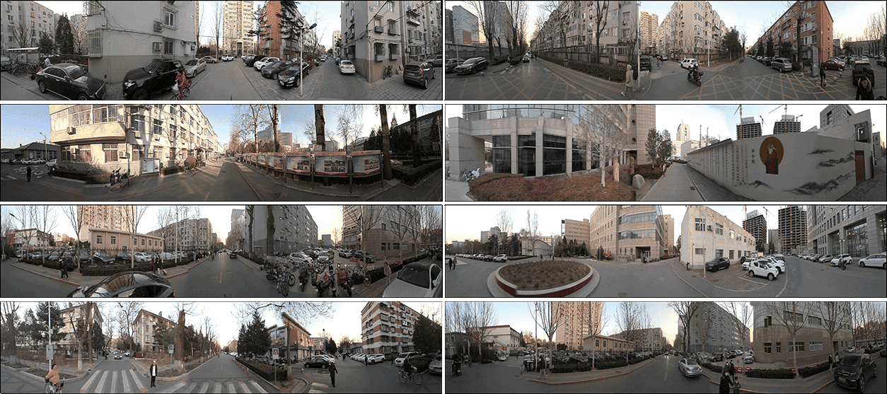
ChatStitch For system-level perception tasks involving Large Language Models, we conducted tests on our own real-world datasets. We aligned the positioning data from integrated navigation with panoramic image data based on GPS time, selecting a 15-second segment of typical vehicle occlusion and revelation for testing. All our Large Language Models utilized GPT-4o.
SV-UDIS. For the multi-image stitching task under the non-global-overlapping condition, we train and test our model on the UDIS-D[2] dataset and the vehicle surround perception dataset released by MCOV-SLAM[26]. For more experimental settings and implementation details, please refer to our supplementary materials.
V-B Results
V-B1 System Results
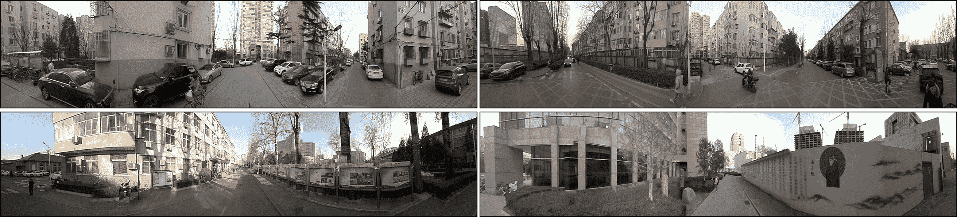
Results with language commands. We have selected two categories of commands, complex and abstract, to represent the most commonly used forms of human language. Complex commands consist of sentences with multiple meanings, detailed instructions, and several directives, while abstract commands are highly generalized and concise ultimate directives. To better demonstrate the perspective capabilities of ChatStitch, we have utilized images captured by an Insta360 camera to create panoramic views that serve as the background in our results.
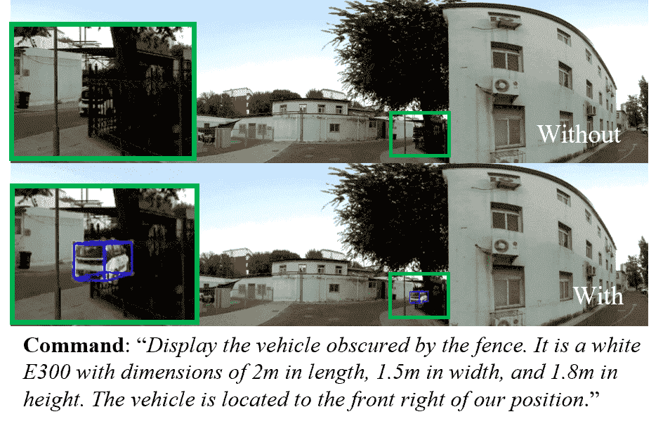
Complex command. We provided the system with detailed information about the type, size, and location of collaborative vehicles. Fig. 5 displays the final results. From this, we can observe that: 1) all the information requested in the complex commands has been successfully addressed, and 2) the intuitive effects of potential collaborative targets are visible even behind obstructing buildings.
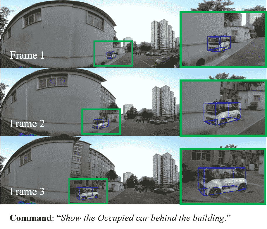
Abstract command. We issued a highly generalized final effect command to the system. The outcome is visible in Fig. 6. From this, it is evident that the highly generalized command contains minimal simple information.
Comparison with Single LLM. We attempted to consolidate all instructions into a single LLM model and compared the outcomes with those derived from a multi-agent decomposition. The results, as shown in Table II, indicate that multi-agent systems demonstrate a better understanding of abstract instructions.
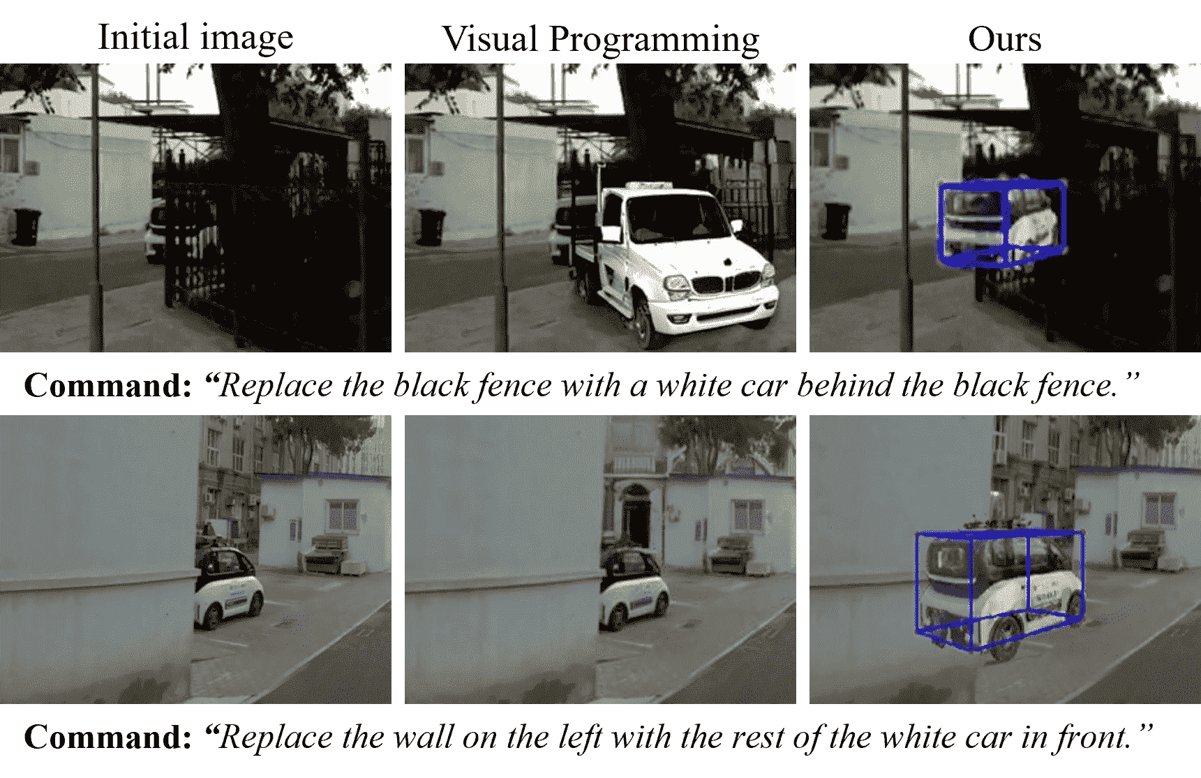
Comparison with Visual Programming(VisProg)[70]. We utilized VisProg object replacement operation to remove occlusions and compared the results with our method, as shown in Fig. 7. ChatStitch accurately performed perspective adjustment and localization of occluded objects, whereas VisProg consistently produced incorrect results. The reason for this discrepancy is that VisProg does not inherently support perspective, and is unable to obtain information about occluded objects.
V-B2 Stitching Results
We conducted extensive experiments on the UDIS-D[2] dataset and the MCOV-SLAM[26] dataset to demonstrate the performance of our proposed stitching framework, especially its ability to handle multi-image stitching tasks under the non-global-overlapping condition.
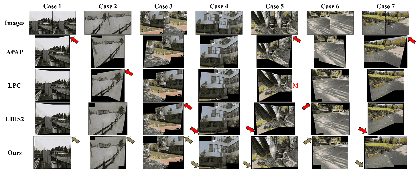
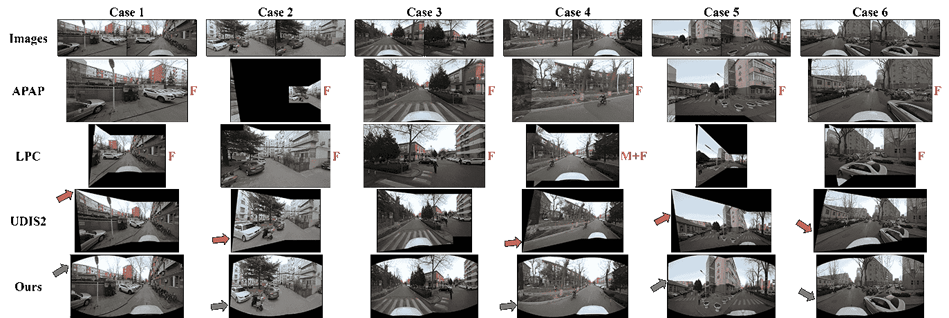
Quantitative comparison. We first conduct multi-image stitching comparison with UDIS2[3] on the two datasets, calculating PSNR and SSIM metrics to compare the image warping and alignment performance. The results are shown in Table III, where represents the identity matrix, indicating no warping or alignment of the target image, serving as a reference. The evaluation results are divided into three levels based on performance, as described in UDIS[2] and UDIS2[3]. Next, we conduct two-image stitching comparison with other classic methods[66, 67, 68, 2] on these two datasets. The results are shown in Table IV.
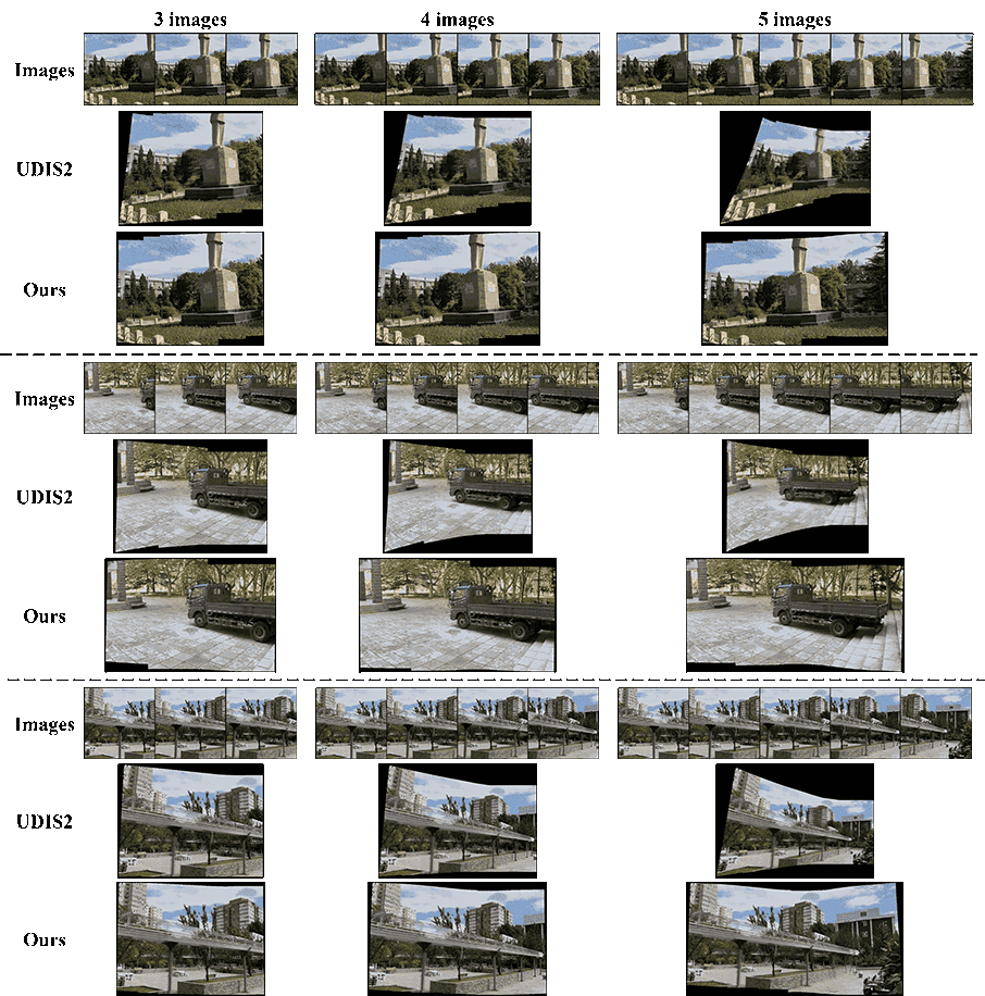
Qualitative comparison. Fig. 8 shows the qualitative results of two-image stitching on the two datasets. It can be seen that even at extremely low overlap rates, our method can still smoothly warp the target image. Fig. 9 shows the results of multi-image stitching under the non-global-overlapping condition using our method. We present more comparison results in our supplementary materials.
Ablation studies. We investigated the impact of cylindrical projection and rectangular warping constraints on the effects of two-image and multi-image stitching. Both quantitative and qualitative experimental results are reported in the supplementary material.
VI Conclusion
This paper introduces ChatStitch, the first collaborative perception system capable of unveiling obscured blind spot information through natural language commands integrated with external digital assets. To adeptly handle complex or abstract commands, ChatStitch employs a multi-agent collaborative framework based on Large Language Models. For achieving photorealistic collaborative perception, we propose SV-UDIS within ChatStitch, which stitches surround-view images in driving scenarios. Experiments demonstrate that ChatStitch can generate photorealistic collaborative perception outcomes that effectively respond to a variety of human language commands, enabling a perspective view of occluded objects. In the future, we will focus on integrating more collaborative perception functionalities such as object detection and depth estimation.
Appendix A Contents
In this document, we provide the following supplementary contents:
-
•
Discussion of Multi-image Stitching Tasks (Section I; Appendix B).
-
•
More Details about Agents (Section III-A; Appendix C)
-
•
More Details about the Pipeline of SV-UDIS (Section IV-B; Appendix D).
-
•
More Details about Experimental settings (Section V-A; Appendix E).
-
•
More Experiments of SV-UDIS (Section V-B2; Appendix F).
Appendix B Discussion of Multi-image Stitching Tasks
Most stitching algorithms focus on stitching two images. Theoretically, multi-image stitching can be achieved by performing multiple pairwise stitching. However, the final stitching effect is influenced by various factors such as the overlapping rate of the input images and the design of the stitching algorithm. In this section, we discuss the problems that may arise when extending a two-image stitching algorithm to multi-image stitching.
SoTA two-image stitching methods (such as APAP[66], AANAP[69], LPC[68], UDIS[2], UDIS2[3], etc.) typically select one image as the reference image and another image as the target image, then warp the target image to achieve alignment. If the multiple images to be stitched satisfy the global-overlapping condition described in Eq. 2, it is only necessary to select a common reference image, and then take turns to warp all other images as the target image, to achieve a good multi-image stitching result. In this case, the multi-image stitching problem can be transformed into a two-image stitching problem under no cumulative distortion, as shown in Fig. 2(a).
However, the surround-view images in autonomous driving scenarios usually satisfy the non-global-overlapping condition described in Eq. 1. In this case, it is necessary to first stitch two adjacent images together, and then stitch them with the next image, and so on. This recursive stitching approach will cause the image distortion (especially projective distortion) to accumulate gradually during the stitching process, resulting in significant distortion in the final result. In addition, images that satisfy the non-global-overlapping condition usually have a lower overlap rate. Existing SoTA methods already show serious distortion when stitching two images, and may even fail to complete multi-image stitching, as shown in Fig. 19 and Fig. 16.
In this paper, our goal is to achieve multi-image stitching under the non-global-overlapping condition in autonomous driving scenarios. We maintain spatial consistency under a large field of view through cylindrical projection and combine it with rectangular warping constraints to reduce projective distortion. Finally, we calculate the global control point motion through our motion propagation strategy to achieve globally consistent multi-image stitching.
Appendix C More Details about Agents
In ChatStitch, agents are composed of specially designed LLM modules paired with corresponding functions. They have equal access to system data and the ability to manage their own parameters. This section provides a detailed overview of agent design and typical methods.
C-A Example of agent prompt
We employ the GPT-4o model as the language interface for the agent modules. Each agent’s prompt includes its role definition, a basic description of its corresponding function, and descriptions of both input and output data. To optimize the performance of the LLM and its corresponding function, the LLM is tasked with translating complex instructions into parameters stored in a JSON file, while the function reads this JSON file to execute tasks under the LLM’s parameter control. Additionally, examples are included in the design to clarify specific input and output formats.
It is important to note that, to enhance the reference to external data assets, we have pre-loaded content from the 3D Asset Bank into the LLM module as selectable parameters. This approach allows ChatStitch to adjust its functions according to the actual needs of the scene, thereby enhancing the system’s adaptability. An example of a perspective measurement prompt is shown in Fig. 10.

C-B More Details about 3D Asset Bank
To enhance the utilization of external data assets, we have provided a library of existing vehicle models. The construction of the 3D Asset Bank follows the process outlined below.
-
1.
Photograph the target vehicle while ensuring the following requirements are met: Use a smartphone or camera to capture images by circling around the object. The angle between consecutive shots should not exceed 3°, and ensure there is an overlap between images.
-
2.
Import the collected images into the COLMAP to compute the intrinsic and extrinsic parameters for each image,
-
3.
Utilize the SAM2 model to extract the mask of the target vehicle. By multiplying the original images with the mask images, obtain a set of images featuring only the target vehicle with the background removed.
-
4.
Input the processed images along with the parameters calculated by COLMAP into InstantNGP. After training, this process yields a NeRF model for the specific target vehicle.
Following the guidance of the above process, we can flexibly expand and utilize external data assets. Some example models are shown in Fig. 11.
C-C More Details about Relative Pose Measurement
The LLM of the Relative Pose Measurement Agent receives language instructions from the Task Management Agent and outputs the corresponding vehicle ID parameters. The corresponding function reads the vehicle ID parameters and GPS location information, then calculates the relative pose between the vehicles.
To compute the relative pose between vehicles, the system utilizes a hierarchical coordinate transformation framework, as illustrated in Fig. 12. Several key coordinate systems are defined:
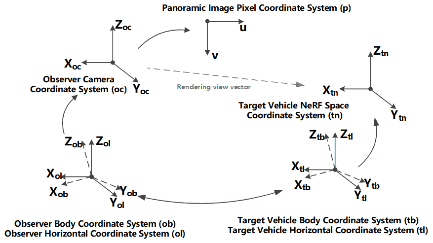
-
•
Observer Camera Coordinate System (oc): Originating from the observer’s camera, this coordinate system represents the relative pose of observed objects.
-
•
Observer Body Coordinate System (ob) and Observer Horizontal Coordinate System (ol): These systems bridge the observer’s camera coordinates with the global frame.
-
•
Target Vehicle Body Coordinate System (tb) and Target Vehicle Horizontal Coordinate System (tl): These systems represent the pose of the target vehicle in its local reference frame.
-
•
Target Vehicle NeRF Space Coordinate System (tn): This system is used to describe the target vehicle’s pose in the NeRF (Neural Radiance Field) space for rendering or reconstruction purposes.
-
•
Panoramic Image Pixel Coordinate System (p): This system links the target vehicle’s pixel position in the panoramic image to its corresponding real-world coordinates.
To calculate the relative pose and rendering vector of the target vehicle in the observer’s camera coordinate system, the system uses the following known inputs:
-
•
GPS coordinates of both the observer vehicle and the target vehicle.
-
•
The transformation between the Observer Body Coordinate System (ob) and the Observer Camera Coordinate System (oc), provided by the camera’s intrinsic and extrinsic parameters.
-
•
The transformation between the Target Vehicle Body Coordinate System (tb) and the Target Vehicle NeRF Space Coordinate System (tn).
The output is the pixel coordinates of the target vehicle in the observer’s camera image plane and the corresponding rendering direction vector.
-
1.
GPS-Based Global Transformation: Using the GPS coordinates of the observer vehicle and the target vehicle, the relative position of the target vehicle in the Observer Body Coordinate System (ob) is calculated. Denoting the GPS coordinates as for the observer and for the target, their relative position in the observer’s body frame is computed via:
where accounts for the Earth’s curvature and local alignment.
-
2.
Transformation to Observer Camera Coordinate System: The position of the target vehicle in the observer’s camera coordinate system is obtained using the known extrinsic transformation matrix (camera pose with respect to the observer body):
-
3.
Projection to Image Plane: The 3D point is projected onto the image plane using the camera’s intrinsic matrix . The pixel coordinates are given by:
where , and are focal lengths, while are the principal point offsets.
-
4.
Rendering Vector Calculation: The rendering vector in the Target Vehicle NeRF Space Coordinate System (tn) is calculated by first transforming the position in the observer’s camera coordinate system to the target vehicle’s NeRF space using:
where is the transformation from the target body to the NeRF space, and is derived from the relative pose between the two vehicles.
The rendering vector is then normalized as:
By following this hierarchical process, the system accurately computes the pixel coordinates of the target vehicle in the observer’s camera image and determines the corresponding rendering direction vector in the target vehicle’s NeRF space.
Appendix D More Details about the Pipeline of SV-UDIS
The framework of the SV-UDIS algorithm proposed in Section IV is shown in Fig. 4. Our goal is to construct a self-supervised stitching framework with learnable parameters , which takes images satisfying the non-global-overlapping condition described in Eq. 1 as input, and stitches them to generate a panoramic image . It is defined as
| (5) |
In this section, we provide a detailed explanation of the aspects omitted in the main text, which include cylindrical projection, optimization function of warping, and multi-image composition.
D-A Cylindrical Projection
For any pixel point on the input image , it is projected into the camera coordinate system according to the camera’s internal parameters , then transformed into the cylindrical latitude and longitude coordinate system , and finally unfolded to obtain the pixel coordinates on the projected image. The specific process is:
| (6) | ||||
The above is the forward projection process. However, to obtain a cylindrical projected image, it is necessary to reverse project the point on the cylindrical image to the corresponding pixel point on the original image, and perform pixel interpolation to obtain a complete cylindrical image. The specific process is as follows:
| (7) | ||||
D-B Optimization Function of Warping
The complete image warping loss function includes three parts: alignment constraint , distortion constraint , and the rectangular warping constraint we proposed. The alignment and distortion terms are consistent with [3].
| (8) |
The rectangular warping constraints described in Eq. 4 we proposed includes three parts: rectangle shape constraint , rectangle size constraint , and grid folding penalty .
For the rectangle shape constraint, we hope that the warped grid as a whole maintains horizontal or vertical orientation. Denoting the sets of horizontal and vertical edges of the warped grid as and , and the unit vectors in the horizontal and vertical directions as and , respectively. We define this constraint as follows:
| (9) | ||||
For the rectangle size constraint, we aim to minimize significant changes in the length of the warped grid. We define this constraint as follows:
| (10) | ||||
For the grid folding penalty, the warped grid should not exhibit folding phenomena, that is, the relative positional relationship among all grid edges — up, down, left, and right — should remain unchanged. Fig. 13 provides a schematic diagram of the grid folding phenomenon, where the grid looks like a rolled-up piece of paper, which can severely affect the warping of the target image. Therefore, we control the orientation of the grid edge vector and through the function . It is specifically defined as follows:
| (11) | ||||
D-C Multi-Images Composition
We adopt the unsupervised seamless composition module proposed by UDIS2[3] for image composition, and extend it to multi-image stitching. For the warped images and masks, we also take two adjacent images as a pair, and then predict the composition masks for each pair of images. At this point, except for the two images located at the edge of the field of view, each other image has two composition masks. Multiplying them together gives us the final composition masks shown in Fig. 4. Finally, the final stitched image can be generated using the warped images and the final composition masks.
Appendix E More Details about Experimental settings
E-A System-level Perception Experimental Details
As shown in Fig. 14, the target vehicle of the system uses a Baojun E100, while the chase vehicle employs a Baojun E300. The distance between the two vehicles is 5 meters, and the moving speed during the experiment is 10 km/h. The chase vehicle is equipped with a camera model of insta360 Pro 2, which has a diameter of 143 mm and utilizes 6 x 200° F2.4 fisheye lenses. Pose estimation is achieved using integrated navigation, and the photos obtained have a resolution of 8k, with the image format being JPEG.
E-B Visual Programming Comparison Experimental Details
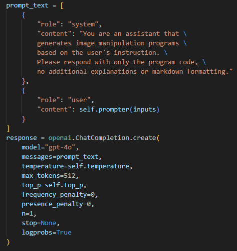
We have configured the experimental environment for Visual Programming on a server and successfully run the natural language image editing test. The experimental platform is based on Ubuntu 20.04.2 LTS, with the CUDA 12.2 graphics acceleration library. The system is equipped with an NVIDIA GeForce RTX 3090 Ti GPU and an Intel(R) Xeon(R) Gold 5215 CPU @ 2.50GHz. The experimental environment was created and deployed using Anaconda, with Python 3.10 as the programming language. The dependencies installed are listed in Table V. We replaced the original text-davinci-003 model with GPT-4o and modified the API call format to adapt to GPT-4o, as detailed in Fig. 15.
| Open-source library name | Version |
| openai | 0.28.0 |
| ipdb | 0.13.9 |
| Pillow | 9.2.0 |
| transformers | 4.27.2 |
| pytest | 7.1.3 |
| opencv-python | 4.6.0.66 |
| scipy | 1.9.2 |
| face-detection | 0.2.2 |
| augly | 1.0.0 |
| diffusers | 0.14.0 |
| accelerate | 0.17.1 |
| ipykernel | 6.15.2 |
E-C SV-UDIS Experimental Details
To verify the performance of the proposed SV-UDIS algorithm, we train and test our model on the UDIS-D[2] dataset and the vehicle surround perception dataset released by MCOV-SLAM[26]. For the UDIS-D dataset, when performing two-image stitching, we use the original dataset released by Nie et al.[2]; when performing multi-image stitching, we extract a portion of data from it and reorganize it into the input form of multi-image stitching. For the MCOV-SLAM dataset, we extract a set of surround image data every 50 frames from the original image sequence released by Pan et al[26]., and randomly divide them into training and testing sets at a ratio of 0.85 for the training set. Additionally, when using the UDIS2[3] method for multi-image stitching, the first step is to stitch two adjacent images together, then stitch them with the next image, and so on.
We train our multi-warp network on these two datasets for 150 epochs, with settings for the optimizer, learning rate, and number of control points consistent with UDIS2[3]. For the multi-warp stage, , , and are set to 0.5, 0.2, and 10, respectively. For the multi-composition stage, we use the pretrained model provided by UDIS2[3]. All implementations are based on PyTorch and the NVIDIA RTX 4090 GPU.
Appendix F More Experiments of SV-UDIS
F-A Two-Image Stitching
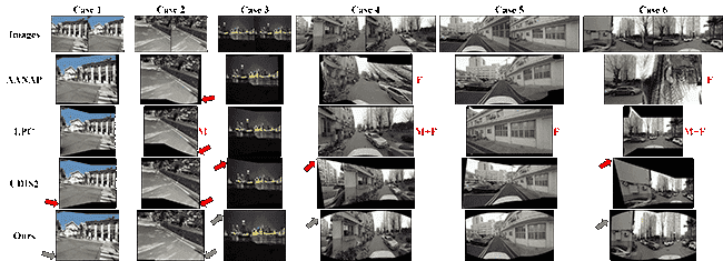
Fig. 18 and Fig. 19 respectively show the comparison of two-image stitching results on the UDIS-D[2] and MCOV-SLAM[26] datasets. Traditional methods APAP[66] and LPC[68] experienced a large number of stitching failures on the MCOV-SLAM dataset. Although UDIS2[3] can achieve good alignment results on both datasets, there is serious projective distortion, leading to severe stretching in the warped images. In contrast, our method can achieve precise alignment while reducing the projective distortion of the warped image, providing a solid foundation for multi-image stitching.
F-B Multi-Image Stitching
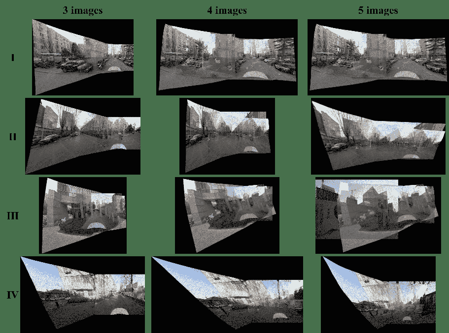
Fig. 20 shows a comparison of multi-image stitching results on the UDIS-D[2] dataset using our method and UDIS2[3]. As can be seen, our method, through the motion propagation and rectangular warping constraints, can effectively extend two-image stitching to multi-image stitching, ensuring alignment accuracy while reducing projective distortion.
Fig. 16 shows the multi-image stitching results of UDIS2[3] on the MOCV-SLAM[26] dataset. When stitching three images, UDIS2 already shows signs of stitching failure. When stitching 4 or 5 images, UDIS2 almost completely fails to stitch. In contrast, Fig. 21 shows the results of stitching five images on the MCOV-SLAM dataset using our proposed SV-UDIS.
F-C Ablation Studies
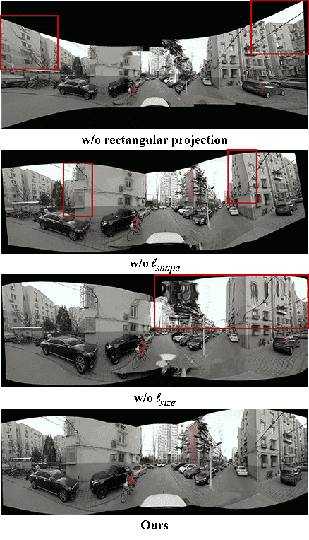
We conduct ablation studies on cylindrical projection and different rectangular warping constraints. The quantitative results and qualitative results are shown in Table VI and Fig. 17, respectively. From these, it can be seen that:
-
•
Cylindrical projection can effectively improve the alignment accuracy on the MCOV-SLAM[26] dataset, and can significantly alleviate the projective distortion when stitching multiple images.
-
•
The rectangular shape constraint may reduce the alignment accuracy, but it can effectively alleviate the geometric structure distortion and skewness when stitching multiple images.
-
•
The rectangular size constraint may slightly reduce the alignment accuracy, but it can effectively alleviate the blurring of the image caused by drastic changes in grid size.
-
•
The rectangular fold constraint can slightly improve the alignment accuracy, while avoiding the grid folding phenomenon shown in Fig. 13.
| Datasets | Methods | 2 images | 3 images | 4 images | 5 images | |||||||
| PSNR | SSIM | PSNR | SSIM | PSNR | SSIM | PSNR | SSIM | |||||
|
w/o | 24.60 | 0.820 | 23.95 | 0.794 | 24.17 | 0.803 | 24.09 | 0.804 | |||
| w/o | 24.41 | 0.807 | 23.74 | 0.786 | 24.03 | 0.796 | 23.94 | 0.797 | ||||
| w/o | 24.10 | 0.796 | 23.44 | 0.777 | 23.62 | 0.783 | 23.52 | 0.784 | ||||
| Ours | 24.28 | 0.803 | 23.58 | 0.784 | 23.77 | 0.790 | 23.62 | 0.789 | ||||
|
w/o cylindrical projection | 15.11 | 0.592 | 15.39 | 0.572 | 15.28 | 0.595 | 15.10 | 0.572 | |||
| w/o | 15.81 | 0.662 | 15.87 | 0.649 | 15.77 | 0.665 | 15.59 | 0.638 | ||||
| w/o | 13.92 | 0.549 | 14.21 | 0.540 | 13.97 | 0.561 | 13.83 | 0.528 | ||||
| w/o | 15.66 | 0.654 | 15.24 | 0.632 | 15.72 | 0.653 | 15.35 | 0.619 | ||||
| Ours | 15.67 | 0.655 | 15.31 | 0.634 | 15.73 | 0.655 | 15.36 | 0.619 | ||||
References
- [1] P. Du, J. Ning, J. Cui, S. Huang, X. Wang, and J. Wang, “Geometric structure preserving warp for natural image stitching,” in 2022 IEEE/CVF Conference on Computer Vision and Pattern Recognition (CVPR), 2022, pp. 3678–3686.
- [2] L. Nie, C. Lin, K. Liao, S. Liu, and Y. Zhao, “Unsupervised deep image stitching: Reconstructing stitched features to images,” IEEE Transactions on Image Processing, vol. 30, pp. 6184–6197, 2021.
- [3] ——, “Parallax-tolerant unsupervised deep image stitching,” in 2023 IEEE/CVF International Conference on Computer Vision (ICCV), 2023, pp. 7365–7374.
- [4] C. Zhu, Y. Yang, H. Liang, Z. Dong, and M. Fu, “Uvss: Unified video stabilization and stitching for surround view of tractor-trailer vehicles,” in 2023 IEEE/RSJ International Conference on Intelligent Robots and Systems (IROS), 2023, pp. 9014–9020.
- [5] A. Wang, H. Chen, L. Liu, K. Chen, Z. Lin, J. Han, and G. Ding, “Yolov10: Real-time end-to-end object detection,” arXiv preprint arXiv:2405.14458, 2024.
- [6] Z. Li, X. Xu, S. Lim, and H. Zhao, “Unimode: Unified monocular 3d object detection,” in Proceedings of the IEEE/CVF Conference on Computer Vision and Pattern Recognition, 2024, pp. 16 561–16 570.
- [7] Z. Liu, H. Sakuma, and M. Okutomi, “Vsrd: Instance-aware volumetric silhouette rendering for weakly supervised 3d object detection,” in Proceedings of the IEEE/CVF Conference on Computer Vision and Pattern Recognition, 2024, pp. 17 354–17 363.
- [8] Y. Ranasinghe, D. Hegde, and V. M. Patel, “Monodiff: Monocular 3d object detection and pose estimation with diffusion models,” in Proceedings of the IEEE/CVF Conference on Computer Vision and Pattern Recognition, 2024, pp. 10 659–10 670.
- [9] Z. Xu, D. Wu, C. Yu, X. Chu, N. Sang, and C. Gao, “Sctnet: Single-branch cnn with transformer semantic information for real-time segmentation,” in Proceedings of the AAAI Conference on Artificial Intelligence, vol. 38, no. 6, 2024, pp. 6378–6386.
- [10] Y. Xiong, B. Varadarajan, L. Wu, X. Xiang, F. Xiao, C. Zhu, X. Dai, D. Wang, F. Sun, F. Iandola et al., “Efficientsam: Leveraged masked image pretraining for efficient segment anything,” in Proceedings of the IEEE/CVF Conference on Computer Vision and Pattern Recognition, 2024, pp. 16 111–16 121.
- [11] A. Wang, H. Chen, Z. Lin, J. Han, and G. Ding, “Repvit: Revisiting mobile cnn from vit perspective,” in Proceedings of the IEEE/CVF Conference on Computer Vision and Pattern Recognition, 2024, pp. 15 909–15 920.
- [12] N. Cavagnero, G. Rosi, C. Cuttano, F. Pistilli, M. Ciccone, G. Averta, and F. Cermelli, “Pem: Prototype-based efficient maskformer for image segmentation,” in Proceedings of the IEEE/CVF Conference on Computer Vision and Pattern Recognition, 2024, pp. 15 804–15 813.
- [13] A. Dorri, S. S. Kanhere, and R. Jurdak, “Multi-agent systems: A survey,” Ieee Access, vol. 6, pp. 28 573–28 593, 2018.
- [14] Y. Li, D. Ma, Z. An, Z. Wang, Y. Zhong, S. Chen, and C. Feng, “V2x-sim: Multi-agent collaborative perception dataset and benchmark for autonomous driving,” IEEE Robotics and Automation Letters, vol. 7, no. 4, pp. 10 914–10 921, 2022.
- [15] R. Xu, H. Xiang, X. Xia, X. Han, J. Li, and J. Ma, “Opv2v: An open benchmark dataset and fusion pipeline for perception with vehicle-to-vehicle communication,” in 2022 International Conference on Robotics and Automation (ICRA). IEEE, 2022, pp. 2583–2589.
- [16] H. Yu, Y. Luo, M. Shu, Y. Huo, Z. Yang, Y. Shi, Z. Guo, H. Li, X. Hu, J. Yuan et al., “Dair-v2x: A large-scale dataset for vehicle-infrastructure cooperative 3d object detection,” in Proceedings of the IEEE/CVF Conference on Computer Vision and Pattern Recognition, 2022, pp. 21 361–21 370.
- [17] Y. Hu, S. Fang, Z. Lei, Y. Zhong, and S. Chen, “Where2comm: Communication-efficient collaborative perception via spatial confidence maps,” Advances in neural information processing systems, vol. 35, pp. 4874–4886, 2022.
- [18] Z. Lei, S. Ren, Y. Hu, W. Zhang, and S. Chen, “Latency-aware collaborative perception,” in European Conference on Computer Vision. Springer, 2022, pp. 316–332.
- [19] A. Swerdlow, R. Xu, and B. Zhou, “Street-view image generation from a bird’s-eye view layout,” IEEE Robotics and Automation Letters, 2024.
- [20] K. Yang, E. Ma, J. Peng, Q. Guo, D. Lin, and K. Yu, “Bevcontrol: Accurately controlling street-view elements with multi-perspective consistency via bev sketch layout,” arXiv preprint arXiv:2308.01661, 2023.
- [21] Z. Yang, Y. Chen, J. Wang, S. Manivasagam, W.-C. Ma, A. J. Yang, and R. Urtasun, “Unisim: A neural closed-loop sensor simulator,” in CVPR, 2023.
- [22] Y. Hu, Y. Lu, R. Xu, W. Xie, S. Chen, and Y. Wang, “Collaboration helps camera overtake lidar in 3d detection,” in Proceedings of the IEEE/CVF Conference on Computer Vision and Pattern Recognition, 2023, pp. 9243–9252.
- [23] Z. Wang, S. Fan, X. Huo, T. Xu, Y. Wang, J. Liu, Y. Chen, and Y.-Q. Zhang, “Vimi: Vehicle-infrastructure multi-view intermediate fusion for camera-based 3d object detection,” arXiv preprint arXiv:2303.10975, 2023.
- [24] Y. Wei, Z. Wang, Y. Lu, C. Xu, C. Liu, H. Zhao, S. Chen, and Y. Wang, “Editable scene simulation for autonomous driving via collaborative llm-agents,” in Proceedings of the IEEE/CVF Conference on Computer Vision and Pattern Recognition, 2024, pp. 15 077–15 087.
- [25] L. Nie, C. Lin, K. Liao, Y. Zhang, S. Liu, R. Ai, and Y. Zhao, “Eliminating warping shakes for unsupervised online video stitching,” in Computer Vision – ECCV 2024. Cham: Springer Nature Switzerland, 2024, pp. 390–407.
- [26] Y. Yang, M. Pan, D. Tang, T. Wang, Y. Yue, T. Liu, and M. Fu, “Mcov-slam: A multicamera omnidirectional visual slam system,” IEEE/ASME Transactions on Mechatronics, vol. 29, no. 5, pp. 3556–3567, 2024.
- [27] S. Shah, D. Dey, C. Lovett, and A. Kapoor, “Airsim: High-fidelity visual and physical simulation for autonomous vehicles,” in Field and Service Robotics, 2017. [Online]. Available: https://arxiv.org/abs/1705.05065
- [28] “Openscanerio Editor,” https://github.com/ebadi/openscenarioeditor. [Online]. Available: https://github.com/ebadi/openscenarioeditor
- [29] “51Sim-One,” https://wdp.51aes.com/news/27. [Online]. Available: https://wdp.51aes.com/news/27
- [30] Y.-C. Liu, J. Tian, C.-Y. Ma, N. Glaser, C.-W. Kuo, and Z. Kira, “Who2com: Collaborative perception via learnable handshake communication,” in 2020 IEEE International Conference on Robotics and Automation (ICRA). IEEE, 2020, pp. 6876–6883.
- [31] Y.-C. Liu, J. Tian, N. Glaser, and Z. Kira, “When2com: Multi-agent perception via communication graph grouping,” in Proceedings of the IEEE/CVF Conference on computer vision and pattern recognition, 2020, pp. 4106–4115.
- [32] Y. Zhou, J. Xiao, Y. Zhou, and G. Loianno, “Multi-robot collaborative perception with graph neural networks,” IEEE Robotics and Automation Letters, vol. 7, no. 2, pp. 2289–2296, 2022.
- [33] R. Xu, Z. Tu, H. Xiang, W. Shao, B. Zhou, and J. Ma, “Cobevt: Cooperative bird’s eye view semantic segmentation with sparse transformers,” arXiv preprint arXiv:2207.02202, 2022.
- [34] H. Xiang, R. Xu, and J. Ma, “Hm-vit: Hetero-modal vehicle-to-vehicle cooperative perception with vision transformer,” in Proceedings of the IEEE/CVF International Conference on Computer Vision, 2023, pp. 284–295.
- [35] J. Xiong, R. Bi, Y. Tian, X. Liu, and D. Wu, “Toward lightweight, privacy-preserving cooperative object classification for connected autonomous vehicles,” IEEE Internet of Things Journal, vol. 9, no. 4, pp. 2787–2801, 2021.
- [36] X. Wang, Z. Zhu, G. Huang, X. Chen, and J. Lu, “Drivedreamer: Towards real-world-driven world models for autonomous driving,” arXiv preprint arXiv:2309.09777, 2023.
- [37] X. Li, Y. Zhang, and X. Ye, “Drivingdiffusion: Layout-guided multi-view driving scene video generation with latent diffusion model,” arXiv preprint arXiv:2310.07771, 2023.
- [38] R. Bi, J. Xiong, Y. Tian, Q. Li, and K.-K. R. Choo, “Achieving lightweight and privacy-preserving object detection for connected autonomous vehicles,” IEEE Internet of Things Journal, vol. 10, no. 3, pp. 2314–2329, 2022.
- [39] R. Gao, K. Chen, E. Xie, L. Hong, Z. Li, D.-Y. Yeung, and Q. Xu, “MagicDrive: Street view generation with diverse 3d geometry control,” in International Conference on Learning Representations, 2024.
- [40] Z. Wu, T. Liu, L. Luo, Z. Zhong, J. Chen, H. Xiao, C. Hou, H. Lou, Y. Chen, R. Yang, Y. Huang, X. Ye, Z. Yan, Y. Shi, Y. Liao, and H. Zhao, “Mars: An instance-aware, modular and realistic simulator for autonomous driving,” CICAI, 2023.
- [41] Y. Han, H. Zhang, H. Li, Y. Jin, C. Lang, and Y. Li, “Collaborative perception in autonomous driving: Methods, datasets, and challenges,” IEEE Intelligent Transportation Systems Magazine, 2023.
- [42] Q. Chen, S. Tang, Q. Yang, and S. Fu, “Cooper: Cooperative perception for connected autonomous vehicles based on 3d point clouds,” in 2019 IEEE 39th International Conference on Distributed Computing Systems (ICDCS). IEEE, 2019, pp. 514–524.
- [43] E. Arnold, M. Dianati, R. de Temple, and S. Fallah, “Cooperative perception for 3d object detection in driving scenarios using infrastructure sensors,” IEEE Transactions on Intelligent Transportation Systems, vol. 23, no. 3, pp. 1852–1864, 2020.
- [44] Y. Li, S. Ren, P. Wu, S. Chen, C. Feng, and W. Zhang, “Learning distilled collaboration graph for multi-agent perception,” Advances in Neural Information Processing Systems, vol. 34, pp. 29 541–29 552, 2021.
- [45] T.-H. Wang, S. Manivasagam, M. Liang, B. Yang, W. Zeng, and R. Urtasun, “V2vnet: Vehicle-to-vehicle communication for joint perception and prediction,” in Computer Vision–ECCV 2020: 16th European Conference, Glasgow, UK, August 23–28, 2020, Proceedings, Part II 16. Springer, 2020, pp. 605–621.
- [46] R. Xu, H. Xiang, Z. Tu, X. Xia, M.-H. Yang, and J. Ma, “V2x-vit: Vehicle-to-everything cooperative perception with vision transformer,” in European conference on computer vision. Springer, 2022, pp. 107–124.
- [47] Y. Yuan, H. Cheng, and M. Sester, “Keypoints-based deep feature fusion for cooperative vehicle detection of autonomous driving,” IEEE Robotics and Automation Letters, vol. 7, no. 2, pp. 3054–3061, 2022.
- [48] M. Fu, H. Liang, C. Zhu, Z. Dong, R. Sun, Y. Yue, and Y. Yang, “Image stitching techniques applied to plane or 3-d models: A review,” IEEE Sensors Journal, vol. 23, no. 8, pp. 8060–8079, 2023.
- [49] N. Yan, Y. Mei, L. Xu, H. Yu, B. Sun, Z. Wang, and Y. Chen, “Deep Learning on Image Stitching With Multi-viewpoint Images: A Survey,” Neural Processing Letters, vol. 55, no. 4, pp. 3863–3898, Aug. 2023. [Online]. Available: https://doi.org/10.1007/s11063-023-11226-z
- [50] H. Wu, C. Bao, Q. Hao, J. Cao, and L. Zhang, “Improved unsupervised stitching algorithm for multiple environments superudis,” Sensors, vol. 24, no. 16, 2024. [Online]. Available: https://www.mdpi.com/1424-8220/24/16/5352
- [51] J. Ni, Y. Li, C. Ke, Z. Zhang, W. Cao, and S. X. Yang, “A fast unsupervised image stitching model based on homography estimation,” IEEE Sensors Journal, vol. 24, no. 18, pp. 29 452–29 467, 2024.
- [52] L. Nie, C. Lin, K. Liao, M. Liu, and Y. Zhao, “A view-free image stitching network based on global homography,” Journal of Visual Communication and Image Representation, vol. 73, p. 102950, 2020. [Online]. Available: https://www.sciencedirect.com/science/article/pii/S1047320320301784
- [53] D.-Y. Song, G. Lee, H. Lee, G.-M. Um, and D. Cho, “Weakly-supervised stitching network for real-world panoramic image generation,” in Computer Vision – ECCV 2022, S. Avidan, G. Brostow, M. Cissé, G. M. Farinella, and T. Hassner, Eds. Cham: Springer Nature Switzerland, 2022, pp. 54–71.
- [54] D.-Y. Song, G.-M. Um, H. K. Lee, and D. Cho, “End-to-end image stitching network via multi-homography estimation,” IEEE Signal Processing Letters, vol. 28, pp. 763–767, 2021.
- [55] L. Nie, C. Lin, K. Liao, and Y. Zhao, “Learning edge-preserved image stitching from multi-scale deep homography,” Neurocomputing, vol. 491, pp. 533–543, 2022. [Online]. Available: https://www.sciencedirect.com/science/article/pii/S0925231221018701
- [56] H. Caesar, V. Bankiti, A. H. Lang, S. Vora, V. E. Liong, Q. Xu, A. Krishnan, Y. Pan, G. Baldan, and O. Beijbom, “nuscenes: A multimodal dataset for autonomous driving,” in 2020 IEEE/CVF Conference on Computer Vision and Pattern Recognition (CVPR), 2020, pp. 11 618–11 628.
- [57] P. Sun, H. Kretzschmar, X. Dotiwalla, A. Chouard, V. Patnaik, P. Tsui, J. Guo, Y. Zhou, Y. Chai, B. Caine, V. Vasudevan, W. Han, J. Ngiam, H. Zhao, A. Timofeev, S. Ettinger, M. Krivokon, A. Gao, A. Joshi, Y. Zhang, J. Shlens, Z. Chen, and D. Anguelov, “Scalability in perception for autonomous driving: Waymo open dataset,” in 2020 IEEE/CVF Conference on Computer Vision and Pattern Recognition (CVPR), 2020, pp. 2443–2451.
- [58] P. Xiao, Z. Shao, S. Hao, Z. Zhang, X. Chai, J. Jiao, Z. Li, J. Wu, K. Sun, K. Jiang, Y. Wang, and D. Yang, “Pandaset: Advanced sensor suite dataset for autonomous driving,” in 2021 IEEE International Intelligent Transportation Systems Conference (ITSC), 2021, pp. 3095–3101.
- [59] A. Vaswani, N. Shazeer, N. Parmar, J. Uszkoreit, L. Jones, A. N. Gomez, L. Kaiser, and I. Polosukhin, “Attention is all you need,” in Proceedings of the 31st International Conference on Neural Information Processing Systems, ser. NIPS’17. Red Hook, NY, USA: Curran Associates Inc., 2017, p. 6000–6010.
- [60] “Gpt-4o,” https://openai.com/index/hello-gpt-4o/. [Online]. Available: https://openai.com/index/hello-gpt-4o/
- [61] J. Devlin, M.-W. Chang, K. Lee, and K. Toutanova, “BERT: Pre-training of deep bidirectional transformers for language understanding,” in Proceedings of the 2019 Conference of the North American Chapter of the Association for Computational Linguistics: Human Language Technologies, Volume 1 (Long and Short Papers), J. Burstein, C. Doran, and T. Solorio, Eds. Minneapolis, Minnesota: Association for Computational Linguistics, Jun. 2019, pp. 4171–4186. [Online]. Available: https://aclanthology.org/N19-1423
- [62] T. Müller, A. Evans, C. Schied, and A. Keller, “Instant neural graphics primitives with a multiresolution hash encoding,” ACM Trans. Graph., vol. 41, no. 4, pp. 102:1–102:15, Jul. 2022. [Online]. Available: https://doi.org/10.1145/3528223.3530127
- [63] K. He, X. Zhang, S. Ren, and J. Sun, “Deep residual learning for image recognition,” in 2016 IEEE Conference on Computer Vision and Pattern Recognition (CVPR), 2016, pp. 770–778.
- [64] L. Nie, C. Lin, K. Liao, S. Liu, and Y. Zhao, “Depth-aware multi-grid deep homography estimation with contextual correlation,” IEEE Transactions on Circuits and Systems for Video Technology, vol. 32, no. 7, pp. 4460–4472, 2022.
- [65] D. DeTone, T. Malisiewicz, and A. Rabinovich, “Deep image homography estimation,” 2016. [Online]. Available: https://arxiv.org/abs/1606.03798
- [66] J. Zaragoza, T.-J. Chin, Q.-H. Tran, M. S. Brown, and D. Suter, “As-projective-as-possible image stitching with moving dlt,” IEEE Transactions on Pattern Analysis and Machine Intelligence, vol. 36, no. 7, pp. 1285–1298, 2014.
- [67] T. Liao and N. Li, “Single-perspective warps in natural image stitching,” IEEE Transactions on Image Processing, vol. 29, pp. 724–735, 2020.
- [68] Q. Jia, Z. Li, X. Fan, H. Zhao, S. Teng, X. Ye, and L. J. Latecki, “Leveraging line-point consistence to preserve structures for wide parallax image stitching,” in 2021 IEEE/CVF Conference on Computer Vision and Pattern Recognition (CVPR), 2021, pp. 12 181–12 190.
- [69] C.-C. Lin, S. U. Pankanti, K. N. Ramamurthy, and A. Y. Aravkin, “Adaptive as-natural-as-possible image stitching,” in 2015 IEEE Conference on Computer Vision and Pattern Recognition (CVPR), 2015, pp. 1155–1163.
- [70] T. Gupta and A. Kembhavi, “Visual programming: Compositional visual reasoning without training,” in 2023 IEEE/CVF Conference on Computer Vision and Pattern Recognition (CVPR), 2023, pp. 14 953–14 962.