Demonstration of High-Fidelity Entangled Logical Qubits using Transmons
Abstract
Quantum error correction (QEC) codes are necessary to fault-tolerantly operate quantum computers. However, every such code is inherently limited by its inability to detect logical errors. Here, we propose and implement a method that leverages dynamical decoupling (DD) to drastically suppress logical errors. The key to achieving this is to use the logical operators of the QEC code as DD pulses, which we refer to as logical dynamical decoupling (LDD). The resulting hybrid QEC-LDD strategy is in principle capable of handling arbitrary weight errors. We test QEC-LDD using IBM transmon devices and the code, demonstrating performance that significantly exceeds the capabilities of using either this code or DD in isolation. We present a method that allows for the detection of logical errors affecting logically encoded Bell states, which, in this case, arise primarily from crosstalk among physical qubits. Building on this, we experimentally demonstrate high-fidelity entangled logical qubits.
Quantum error correction (QEC) [1, 2, 3, 4] is fundamental to the realization of fault-tolerant quantum computation [5, 6, 7, 8], ensuring the preservation of quantum information undergoing error processes during computation and storage [9, 10]. Numerous successful experimental demonstrations of QEC across various platforms have been reported over the years [11, 12, 13, 14, 15], with the scale and pace accelerating recently towards genuine fault tolerance [16, 17, 18, 19, 18, 20, 21, 22, 23, 24].
Fault-tolerant quantum computing will require the stability of logical qubits over the potentially hours-long timescales of quantum algorithms solving utility-scale problems [25, 26, 27]. Above threshold, over such timescales low-weight physical errors may transform into logical errors of weight higher than any deployed fixed-distance QEC code can handle. This can become a concern even below threshold since long-range spatial and temporal correlations may develop that violate the assumptions underlying fault tolerance theory [28, 29, 30, 31, 32].
Conventionally, suppressing higher-weight errors requires increasing the QEC code distance, e.g., by means of code concatenation [33, 34], or increasingly larger codes such as is done with surface codes [35, 36], color codes [37], or quantum low-density parity-check codes [38]. Although effective, these strategies result in significant overhead, substantially increasing the number of physical qubits required and the time required to decode and correct errors.
Here, we propose and demonstrate a low-cost method that combines a fixed-distance QEC or quantum error detection (QED) code with dynamical decoupling (DD) [39, 40, 41, 42]. This hybrid method, which we call QEC-LDD, can handle arbitrary-weight errors.
Here, LDD stands for ‘logical dynamical decoupling’; the decoupling sequence is implemented using the logical operators of the QEC code as pulses.
We prove a corresponding QEC-LDD theorem which, informally, posits that the most general set of errors acting on an code, namely errors with weights up to , can all either be suppressed using LDD or corrected using the code, for any . This seemingly paradoxical result is enabled by virtue of the fact that the LDD sequence suppresses all logical errors as well as some physical errors, thus leaving a much smaller subset of errors for the code to handle, which turn out to all be correctable. Notably, these are not the errors the code was originally designed to correct; indeed, the result holds in particular also for purely error detecting codes. The QEC-LDD theorem is a formal result, in the sense that QEC-LDD, if implemented literally as described in the theorem, is not expected to outperform a pure DD protocol (absent any QEC) on physical qubits. Nevertheless, the QEC-LDD theorem serves as a useful framework for less ambitious protocols that do not attempt to remove all errors but instead focus on the more physically relevant subset. We discuss and illustrate this conclusion in detail in this work, in the context of a transmon-based demonstration of entangled logical qubits.
Standard, ‘physical’ DD, where DD pulses act not at the logical level but at the physical qubit level, has recently shown great progress, improving the fidelity of storing quantum states [43, 44, 45, 46, 47, 48, 49], circuits [50, 51, 52], and even the performance of entire algorithms [53, 54, 55, 56]. Furthermore, physical DD can be seamlessly combined with fault-tolerant QEC [57, 58] and several recent QEC experiments have used physical DD profitably [18, 21, 19, 59, 20, 60].
However, such pulse sequences can introduce additional errors due to control imperfections in the pulses and due to crosstalk, potentially overshadowing the benefits of DD. To address this challenge, we design our LDD sequences to be robust against such control errors [61, 62] and crosstalk [63, 64, 65, 66, 67], ensuring that the advantages of logical error suppression are not compromised. This robust design allows our LDD implementation to enhance the protection of the code space as intended, effectively targeting both logical and control errors. We demonstrate the practical utility and advantages of this approach using -qubit IBM quantum processors.
The workhorse in our demonstrations is the quantum error detection code, whose two logical qubits we use to prepare logically encoded Bell states. To demonstrate the effectiveness of LDD in suppressing logical errors, we first need a method to detect such errors. However, this code is constrained by its low distance and is incapable of detecting prevalent logical errors, including crosstalk errors. To overcome this limitation, we design experiments in which, through the use of logically encoded Bell states, we nevertheless unequivocally detect the occurrence of logical errors for a known input logical state. This is then followed by the implementation of various versions of LDD, each employing different subsets of logical operators to construct the sequence. These implementations effectively demonstrate significant suppression of logical errors and substantial improvement in the fidelity of the code space.
The structure of this paper is as follows. In Section I we provide pertinent background on the error model and DD from the perspective of group averaging. We discuss standard Pauli-group DD as well as DD implemented using the stabilizers and or logical operators of a stabilizer code. In Section II we state and prove the QEC-LDD Theorem. We also illustrate the theorem using the example of the code. We then turn to our experimental demonstration of high-fidelity logical Bell states in Section III. This section describes our experimental design and methodology, evidence that both physical DD and error detection with postselection improve logical Bell state fidelity, and finally the evidence that the hybrid QEC-LDD strategy is significantly better.
We conclude in Section IV and provide supporting technical details in the Appendix.
I Background
I.1 Quantum codes and logical errors
An code encodes logical qubits into physical qubits with distance [68]. The weight of an error is the number of physical qubits it affects simultaneously. The highest-weight errors an code can correct or detect are and , respectively. A code is a pure quantum error detection (QED) code, and a distance- QEC code can always be used as a QED code for errors of weight . The code distance is the minimum number of physical qubits that must experience an error to cause an undetectable logical error, i.e., an error forming a logical operation inside the code space. These logical errors can either be inherently present or result from the accumulation of lower-weight errors over time. For example, in the context of superconducting qubits with fixed-frequency couplers, a prevalent challenge is crosstalk [69, 70], which inherently introduces weight-two errors that can present as logical errors for distance- codes.
I.2 Logical dynamical decoupling
Let be the full Pauli group with elements generated by and the phase factors . Let be the Abelian factor group with elements (here is the group of unitary operators on ).
Consider the most general ‘total decoherence’ system-bath interaction for qubits:
| (1) |
We let , the -qubit identity operator. The pure-bath Hamiltonian is harmless.
In its simplest form, accounting only for first-order decoupling and ignoring pulse errors, DD theory can be understood as group symmetrization [71, 72]. Choose a decoupling group that consists of a set of unitary transformations (pulses) acting purely on the system: , where . We assume that each such pulse is a unitary operator defined up to a global phase, i.e. ; however, to simplify the notation we write, e.g., instead of (the equivalence class of up to a global phase). Similarly to and , we assume that can be written as for some group . In particular, we assume that the pulses are instantaneous and cycle over all elements of the group . This yields the DD pulse sequence:
| (2) |
Here, is the pulse interval, is the total duration of one repetition of the sequence, is the free-evolution unitary, and is the group-symmetrized system-bath Hamiltonian, where
| (3) |
is the projection of the arbitrary bounded system-bath operator onto the subalgebra of operators that commute with every element of (i.e., its commutant). We say that decouples (to first order) if where is a constant, including zero.
For example, decouples an arbitrary -qubit system-bath Hamiltonian since then , albeit at a sequence time cost of [40]. To illustrate this, consider ; the most general system-bath Hamiltonian of a single qubit is with . If , then simplifies into the well-known XY4 sequence [73], and indeed, .
Higher-order decoupling sequences are known that achieve suppression up to arbitrary order [i.e., leaving an unsuppressed error term in ] [74, 75, 76, 77, 78], but for simplicity, in this work we restrict our attention to first-order sequences. Note that a common misconception is that DD is not effective against purely Markovian noise [79]; however this is not the case, essentially since even in the Markovian limit the bath can have a nonzero correlation time [80, 81, 82, 83].
In general, decoupling using subgroups of will eliminate parts of , presenting an opportunity to selectively combine DD with QEC [84, 57] while taking advantage of biased noise [85, 86]. Recall that an stabilizer code is defined as the eigenspace of a stabilizer group of order (with commuting generators ). A stabilizer group is any subgroup of that excludes (which implies that it is Abelian). This factors the -qubit Hilbert space into logical qubits with an associated group of canonical logical operators (we use to denote a generating set; ) and syndrome qubits (which can be used to detect errors). Specifically, syndrome qubits can be used to detect Pauli group terms that anticommute with at least one of the stabilizer generators [3]. Since is commutative, operators in can be simultaneously diagonalized. This simultaneous diagonalization partitions the Hilbert space into an orthogonal sum of subspaces, each of dimension , corresponding to choices of eigenvalues of for (each such eigenvalue is ), i.e., different values of the syndrome. We call these “syndrome spaces”. is associated with the trivial (no error, corresponding to eigenvalue of all ) syndrome and that two logical operators act identically on if they only differ by a stabilizer element, i.e., the full group of logical operators is , the centralizer of in .
For a code , the stabilizer group is uniquely defined as
| (4) |
Its centralizer is also uniquely defined. However, the group of canonical logical operators is not unique: one can choose arbitrary stabilizers () and multiply the generators by those to obtain other choices of the group .
It is always possible to write the system-bath interaction [Eq. 1] as
| (5) |
grouping together terms with similar action on the code space . Altogether, this expression has linearly independent terms corresponding to the elements of . Specifically, collects all the distinct Pauli operators (including ); such terms act as the identity operator on the code space and, therefore, are harmless. collects all Pauli operators in ; these terms leave the code space (and each of the other syndrome spaces) invariant but cause harmful logical errors, since by construction, the code cannot detect such errors. Finally, collects all remaining terms in , which correspond to potentially detectable errors: given the value of the syndrome one can either detect all of them or correct some of them.
A key observation is that the decoupling group is arbitrary and may, in particular, be formed from the stabilizer group and/or the group of canonical logical operators of a stabilizer code , or even a subset of either one [87, 72, 88, 89, 58, 90]. One approach for selectively combining DD with QEC, which leverages this flexibility, is to use DD only to suppress the errors between or within the syndrome spaces, including the code space (i.e., errors in ). Errors causing transitions between the syndrome spaces (i.e., elements of ) are the ones the code aims to detect or correct. The former are decoupled by while the latter are decoupled by . For any choice of , the decoupling condition is that there exists at least one element of that anticommutes with a given error. Based on these properties, it was shown in Ref. [58] that combining the full set of stabilizer and canonical logical operator generators to generate the DD group , optimally achieves the goal of decoupling the errors between or within the syndrome spaces, in the sense of minimizing the length of the DD pulse sequence. This is known as ‘stabilizer-logical DD’ (SLDD) and incurs a single sequence cost of , instead of in the case of full Pauli group decoupling. The savings are substantial when . Adding QEC syndrome measurements and recovery operations based on syndrome measurements then detects the remaining errors between syndrome spaces that DD did not suppress [i.e., the terms in the case of a ’th-order DD sequence] or successfully corrects some of them, resulting in a hybrid QEC-DD strategy.
II The QEC-LDD Theorem
The main weakness of SLDD is that it still incurs a cost that is exponential in the number of physical qubits . Here, we present a different hybrid approach, shifting more of the burden for handling correctable errors to the QEC code and using only the logical operators as DD pulses . We call this approach ‘logical DD’ (LDD). Compared to SLDD, this approach has the desired effect of reducing the single sequence time-cost to for first-order decoupling, independent of . Table 1 summarizes the relative resource cost of full Pauli group DD, SLDD, and LDD.
| Comparative DD resource cost | ||
|---|---|---|
| Decoupling group | # of pulses | suppresses all errors afflicting code space / requires QEC |
| Pauli group | Yes / No | |
| SLDD | Yes / No | |
| LDD | No / Yes | |
II.1 Theorem statement and proof
The LDD sequence is purely responsible for decoupling the logical errors acting within each syndrome space, but unlike SLDD, it no longer decouples some of the physical errors between the syndrome spaces. Correcting these errors is accomplished by syndrome measurements in conjunction with error recovery.
For each code there is a choice of which errors to correct: for each of the nontrivial syndromes, one may choose a recovery operation; this choice determines which errors are successfully corrected and which result in a logical error. Once such a choice is made, we call the errors that are successfully corrected “correctable”.
We summarize this in the following theorem:
Theorem 1 (QEC-LDD).
Consider the most general system-bath Hamiltonian acting on qubits [Eq. 5]. Let be an stabilizer code (with any ). Let denote its group of canonical logical operators. Choose the decoupling group , henceforth the LDD group. Then decouples all logical errors, that is, every term in , as well as some errors in . There is a choice of recovery operation such that all remaining non-decoupled errors in are correctable by . Conversely, for any recovery operation chosen in this way, only those errors that are not decoupled by are correctable.
Proof.
We first establish when an error is decoupled. Let be the Hilbert space of qubits. Then and all elements of (and, hence, of and ) are unitary operators on . We let . Consider a term in corresponding to some . It is decoupled if and only if there exists anticommuting with . Indeed, then and
| (6) |
so . If there is no such then all elements of commute with (because every two elements of either commute or anticommute). Then all for all , hence (i.e., the term is undecoupled). It follows that decouples all logical errors, since every such error anticommutes with an element of . The errors in that anticommute with an element of are also decoupled. All terms in are undecoupled since they all commute with .
The key observation in the proof is that the statement of the theorem is invariant under Clifford maps, which we now show.
Now consider any Clifford unitary . Let , be the distance of the code , , , , etc. For a recovery map (for every value of the syndrome) for we can construct the corresponding recovery map for . If the statement of the theorem is true for the original code , then it remains true for because it only depended on the commutation relations between elements of and those are preserved under the group homomorphism . By applying this observation to instead of we observe that the converse also holds.
In 1 in Appendix C, extending earlier methods for stabilizer code encoding [91, 92, 93], we show that for any code and any choice of the canonical logical operators there is a Clifford unitary (which we may call “unencoding circuit”) such that the corresponding code consists of states of the form , where , and consists of Paulis acting trivially on the last qubits. We call such code a trivial code: its logical qubits can be chosen to coincide with the first physical qubits and stabilizer generators can be chosen to be enforcing that the last qubits are set to , and .
It follows that it is sufficient to prove the statement of the theorem for this trivial code. Hence, from now on we assume that is the trivial code described above. is undecoupled if and only if it commutes with all Paulis acting on the first qubits. This is true if and only if acts trivially on the first qubits. (Equivalently, is decoupled if and only if acts non-trivially on one or more of the first qubits.) Measuring the stabilizers is equivalent to measuring the last qubits. Any such measurement outcome corresponds to errors , where and is an arbitrary stabilizer. A (unitary) recovery operation corrects such an error if and only if . In particular, if we apply corresponding to the measured syndrome , we correct all non-decoupled errors, proving the first statement of the theorem. On the other hand, all such recovery maps act trivially on the first qubits, so if acts non-trivially on the first qubits (i.e. if is decoupled), it remains uncorrected by any such procedure. ∎
We emphasize a few key points:
-
•
The claim holds even for (or ), i.e., an error detecting code becomes an error correcting code subject to LDD.
-
•
In fact, the notion of correctable errors used here ignores the code distance altogether. For any distance, the QEC-LDD protocol has at least non-correctable single-qubit errors (these are decoupled by LDD).111Consider the group and divide the physical qubits into three classes according to the action of the elements of on a particular qubit. 1. Every element of acts as on that qubit. 2. Every element of acts as or one other Pauli (, , or ) on that qubit. 3. For every Pauli in there is which acts like that Pauli on that qubit. Let be the number of physical qubits in each class. Restrict every element of to the qubits from class 3. Such a restriction does not change the commutation relations. Let the resulting group be . We have , which in turn is embedded in . Therefore, . The number of uncorrectable single-qubit errors is . E.g., for the code , . For example, in the standard distance- surface code there is a weight error, which can be “corrected” to become a weight error. That does not contradict the theorem, because that error is suppressed by LDD.
-
•
For each syndrome, the corresponding recovery operation is unique up to multiplication by stabilizers.
-
•
All decoupled errors are not correctable; it is the role of LDD to suppress such errors.
II.2 Illustration of the QEC-LDD Theorem: the code
To illustrate the QEC-LDD construction, we analyze the example of the code (see Appendix A for a review of this code). The stabilizer group of this code is . A set of logical operators for the code can be chosen such that , , and , i.e., . Up to a global phase, is the generator set of the -element decoupling group . This LDD group suppresses every logical error in the -element : the group-averaged logical system-bath Hamiltonian vanishes, as every one of its terms is a logical operator that anticommutes with an element of .
The errors that are not suppressed are easily seen to be the -element set , since they commute with all elements of . Each such error is detectable because it anticommutes with at least one element of . Moreover, every such error is correctable since it is equal to the product of the stabilizer and , where can be determined (up to the global phase) from the value of the syndrome. The recovery operation is then the weight-one operator .
Ignoring phases, the Pauli group on physical qubits, , has elements. Of these, are the elements of , are the unsuppressed errors , which leaves other elements such that corresponding anticommutes with at least one element of and is, therefore, suppressed by it.
Appendix C illustrates the unencoding of the code. In this case, decouples all errors on the first two (data) qubits and only or are left as undecoupled bit-flip errors on the last two qubits.
II.3 Avoiding the use of virtual- gates
One of the limitations of our experimental setup is that physical gates are unavailable: fixed-frequency transmons utilize virtual- gates [94, 95]. Such gates are problematic for DD [95]. We now demonstrate that there are DD sequences satisfying the conditions of the QEC-LDD theorem which do not use any physical pulses. To construct such a sequence, we first choose generators of that do not involve physical gates. An example choice would be . One could follow the construction below with this choice. However, in order to improve the ability of the DD sequence to suppress crosstalk we suggest a different choice. First, multiply the original generators of (that is, ) by the stabilizers , , , and , respectively, to obtain . Then, after some group operations, we can write the same group using a different set of generators containing no ’s: . The DD sequence consisting of two repetitions of , , , , , , , then corresponds to the decoupling group , and involves no gates.
This sequence was obtained as follows: denote the generators of (or ) as and choose any Gray code — a sequence of bitstrings such that neighboring bitstrings differ in only a single digit. Finally, pick (for ), where is interpreted as a multiindex (i.e. ). The pulses of the DD sequence are for .
However, in our experiments we found that a decoupling group generated by a subgroup of and a subgroup of works better in practice because of its robustness and ability to suppress crosstalk. The next section is dedicated to demonstrating experimentally how the hybrid QEC-LDD protocol results in a significant fidelity enhancement of entangled logical qubits.
| No DD | XY4 | UR6 | UR8 | UR10 | UR18 | RGA8a | |
|---|---|---|---|---|---|---|---|
III Experimental design and methodology
The data for the experiments we report here were collected on two separate occasions from a total of sets of four-qubit experiments run on the ibm_kyiv [96] quantum processor. Dataset 1, using sets of qubits, was collected during the week of August 12th (2024). Dataset 2, using sets of qubits, was collected on March 1st and 2nd (2025). These four-qubit sets differ from those in dataset 1 in order to test the robustness of our results. The figure captions below specify the dataset. For each data point in our results, fidelity is independently calculated for each qubit set and then bootstrapped by resampling. The mean fidelity and standard deviation are derived from the bootstrapped data, where larger error bars indicate greater variability among the qubit sets.
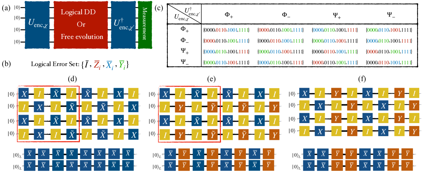
The ibm_kyiv processor consists of coupled, fixed-frequency transmons [97]. Such qubits exhibit an always-on interaction between adjacent pairs [98]. This crosstalk gives rise to weight-2 error terms that correspond to logical errors with our code choice. Other errors of weight , if present, would likewise correspond to logical errors. To demonstrate that LDD can suppress all logical errors, we design an experiment that enables the unequivocal detection of such errors. To this end, we use the two logical qubits of the code to create logical Bell states and . The corresponding encoding circuits , where , create two copies of physical Bell states, followed by the application of a logical controlled-NOT () to generate the logical Bell states (see Appendix A).
To estimate the fidelity of a logical Bell state , we start from the physical ground state , encode into the state of interest by applying , and then let it evolve for some time , either freely or subject to DD.
If after time we unencode by applying , then measuring the bitstring would indicate that no error occurred.
If, instead, we obtain any of the odd-Hamming weight bitstrings, this would signal detection of a physical error, as such states are not in the codespace. The final possibility is that we obtain one of the other even-Hamming weight bitstrings , corresponding to a logical error. This procedure can be used to estimate the probability of finding the ground state as the empirical fraction of ground state measurement outcomes, which is also the fidelity of the logical Bell state .
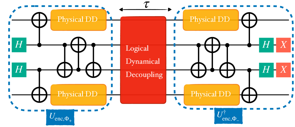
To obtain the fidelity of a logical error, we first observe that each of the logical Bell states is related to the other three logical Bell states through a specific logical error: , where and or ; i.e., a logical operator that acts on either of the two logical qubits. We thus proceed as follows: instead of applying , at we deliberately unencode into a different logical Bell state [see Fig. 1(a)]. In this manner, each of the even-weight bitstrings gives us a measure of the occurrence of one of the logical errors , where is determined by the unencoding we choose [see Fig. 1(b,c)]. Using this methodology, we can detect the occurrence of different types of logical errors and quantify the associated error probability.
In more detail, each row in Fig. 1(c) shows a different initially encoded logical Bell state. Each column corresponds to one of the unencoding circuits. In each unencoding scenario, the different bitstrings indicate that the state being unencoded is either the initial logical Bell state or some other logical Bell state. For example, consider the case where we originally encode and then unencode into at . If the state being unencoded is indeed , then the bitstring signals that a logical error () has occurred. However, if no error has occurred, then due to unencoding into , the result should be the bitstring. Generalizing, it is possible to detect the different logical errors using the experiments indicated in Fig. 1(c).
However, we specifically choose the unencoding so that it is always the bitstring that corresponds to the occurrence of the logical error operator in which we are interested. We make this choice since is the ground state of the system and therefore is robust against relaxation errors. This strongly increases the likelihood that the detected errors are purely logical and are unaffected by thermal relaxation. Note that due to this choice, the bitstring that corresponds to the fidelity of the prepared initial state varies [black color-coded bitstrings in Fig. 1(c)].
From here on, we use the notation to denote the procedure of preparing the encoded logical Bell state and unencoding into , i.e., of using the encoding unitary and the unencoding unitary .
We note that logical state tomography is an alternative method for learning about the performance of LDD, and in particular, for certifying the entanglement of logical Bell states. However, the code imposes some additional challenges in performing logical tomography, which precluded its use in our work; see Appendix D for details.
III.1 Physical dynamical decoupling improves logical Bell state fidelity
We first show that we can substantially improve the logical Bell fidelity by padding the idle gaps of the encoding circuits with physical (as opposed to logical) DD sequences. An idle gap is a temporal circuit segment during which no gates are applied. Such gaps occur, e.g., when a pair of qubits is involved in a two-qubit gate that takes much longer than a single-qubit gate simultaneously being applied to another qubit; the latter is then idle after the completion of the single-qubit gate, while awaiting the completion of the two-qubit gate.
As shown in Fig. 2, we inserted various DD sequences into the idle gaps of Bell state circuits. This includes XY4 [40], universally robust sequences URn [62] for , and RGA8a [61]; the former are illustrated along with robust variants in Fig. 1(d-f).
We performed the experiments (during the week of August 12th 2024) on fourteen different sets of qubits of ibm_kyiv and report the average fidelity values in Table 2. In these experiments, we encoded and unencoded the same state, i.e., used along with . We see that using DD, the encoding fidelity improves by for all four logical Bell states, with XY4 and RGA8a being the top performers (we attribute the lower performance of the longer URn sequences to pulse interference effects [95]).
In all, these results demonstrate that logical Bell state preservation can benefit significantly from physical DD. Having established the utility of physical DD, we proceed to combine it with LDD in the next section.
III.2 Logical error suppression and detection by LDD
For all our experimental results, ‘No DD’ refers to encoding without any physical or logical DD. In all other experiments, we use physical XY4 to pad all the encoding and unencoding circuits gaps, and combine them with various flavors of LDD. This choice allows us to clearly assess the improvements introduced by DD, compared to relying solely on the code’s error detection capabilities.
III.2.1 Logical errors
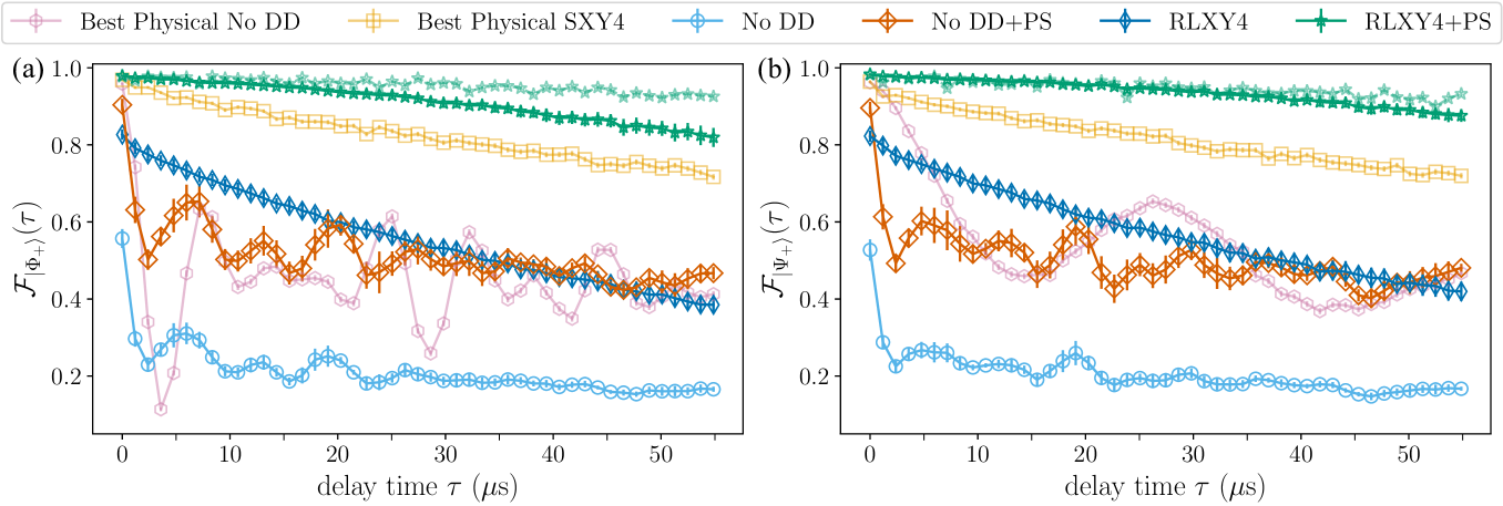
We start by gradually increasing the time delay (up to 55 s) between the encoding and unencoding without DD. This situation is relevant in the context of QEC experiments. For example, one could prepare an encoded qubit and then leave it idle while other logical operations are applied to other encoded qubits [19].
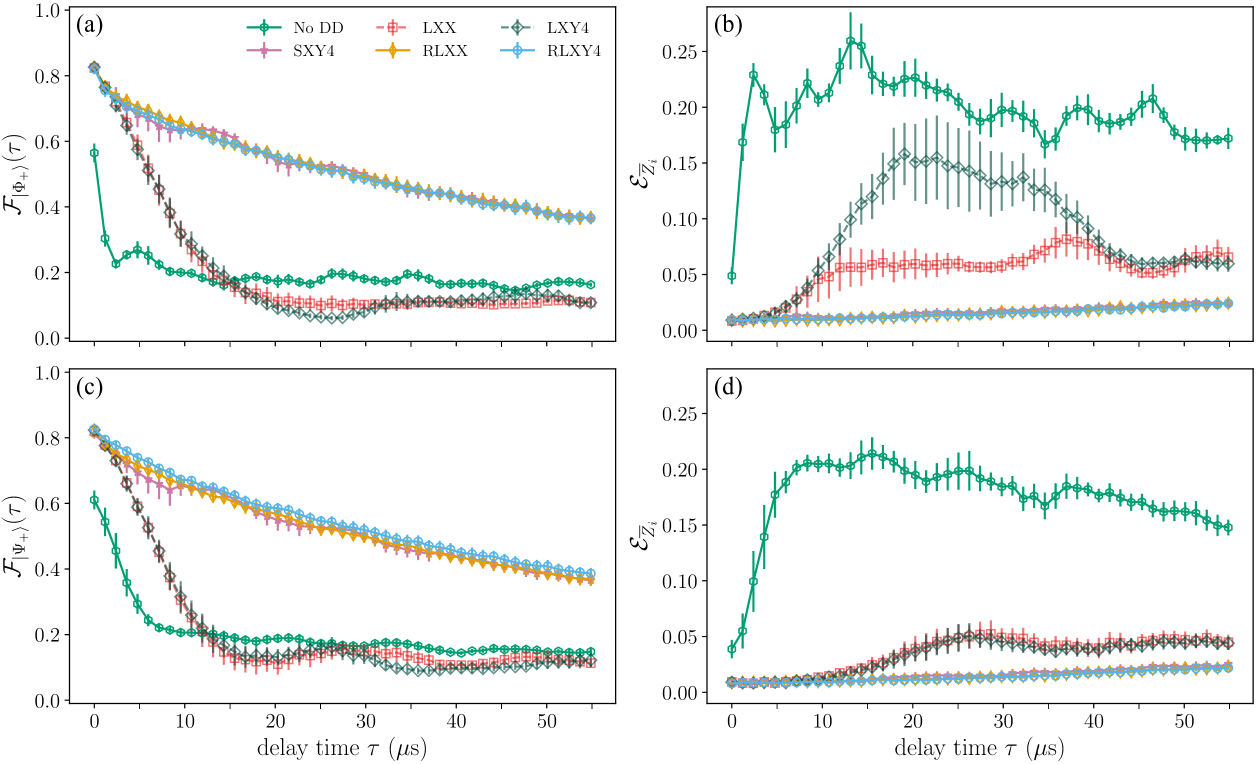
We perform the error detection using the logical Bell states and as discussed in Section III, and display the results in Fig. 3. As can be seen in Fig. 3(a) and (c), without LDD the free evolution fidelity (denoted as No DD) decays rapidly and exhibits crosstalk-induced oscillations. Fig. 3(b) and (d) show that logical errors accumulate over time. We next use two types of LDD sequences to suppress this effect: Logical XX (LXX) and Logical XY4 (LXY4). Physical-level schematics of these LDD sequences are shown in the boxed four-pulse sequences of Fig. 1(d) and (e), respectively (disregarding the tilde notation). Their logical-level counterparts are shown at the bottom of Fig. 1. We generate both LXX and LXY4 using the native logical operations of the code. For example, in the upper part of Fig. 1(d), reading the first column from top to bottom yields , which is the column at the bottom of Fig. 1(d). Reading the pulse sequences from left to right, the staggering (appearance of delays as indicated by the identity operations) is deliberately introduced to suppress crosstalk at the physical level [65]; see Appendix B for more details.
The corresponding results are shown as dashed lines in Fig. 3. At short times (s), these results are better than those without DD because some errors (including crosstalk) are suppressed by both LXX and LXY4. However, at longer times, the benefit is lost and, moreover, small oscillations appear that indicate the presence of coherent errors [99]. To overcome this, we create robust versions of LXY4 and LXX by ensuring that all physical qubits in the code undergo physical DD sequences robust to pulse errors. Specifically, we use the universally robust (UR) sequence family [62], and ensure that each physical qubit undergoes a UR4 sequence, i.e., or , where a tilde denotes an or rotation by instead of . These robust versions, which we call RLXX and RLXY4, are the full sequences shown in Fig. 1(d) and (e). The performance of these sequences is shown by the solid lines in Fig. 3 and exhibits a significant improvement. Notably, the logical Bell state fidelities decay more slowly and without oscillations (panels (a) and (c)), and the logical errors are strongly suppressed (panels (b) and (d)).
In addition, we apply the physical staggered XY4 (SXY4) sequence. This corresponds to applying a single XY4 sequence to each physical qubit but in a staggered manner to reduce crosstalk [65]. This sequence, shown in Fig. 1(f), also corresponds to an LDD sequence for the code (bottom of panel (f)). However, it is not a universal logical sequence, but rather a purely logical--error suppressing sequence. Interestingly, Fig. 3 shows that SXY4 performs on par with RLXX and RLXY4. This finding signals that the dominant logical errors are of -type. We confirm this in the following.
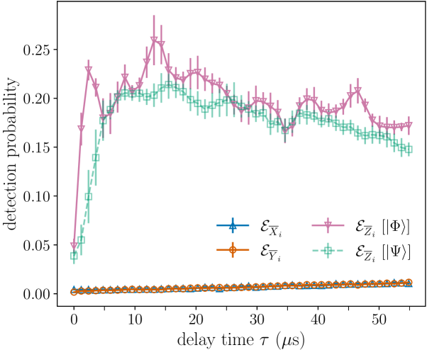
III.2.2 Logical and errors
So far, we have only discussed the detection and suppression of -type logical errors. In order to detect and -type logical errors, we proceed in analogy to the error detection procedure, but with a different unencoding step. Namely, we start by encoding the logical state, and then unencode in either to detect -type errors or in to detect -type errors. The results are shown in Fig. 4 where, for comparison, we have also included the no-DD and results shown in Fig. 3(b,d), which measure -type logical errors. It is clear from Fig. 4 that while unsuppressed logical errors accumulate rapidly, logical errors of and -type grow much more slowly. This confirms that crosstalk is the main source of logical errors.
III.2.3 LDD with postselection
Having implemented LDD, we can further improve the results by using the error detection capability of the code, which allows us to perform postselection. We do so by discarding any measurement outcome outside the logical basis (which would be the result of a physical error); i.e., we only keep measurement results corresponding to the bitstrings .
In Fig. 5(a) and (b) we show the fidelities of and for dataset 2 (Section III). Without DD, the fidelity decays rapidly while exhibiting crosstalk oscillations, as seen for dataset 1 in Fig. 3. The fidelity improves once we perform postselection as described above. This leaves us with bitstrings corresponding to logical states, but logical errors still reduce the fidelity. Using LDD in the form of the RLXY4 sequence – which suppresses both logical errors and physical errors – followed by postselection, we achieve fidelities for and for over a s period. The average fidelities over the same period are 91.12 for and 93.66 for . For the particular set of qubits numbered (light dashed lines), we find that the combination of LDD and postselection yields average fidelities of for and for , which is significantly higher than when we use only the error detection capability of the code: for and for .
III.2.4 Beyond breakeven and the state-of-the-art
Fig. 5 also includes results for physical (unencoded) Bell states. Here we show only the best Bell pair among all pairs we tested, both without DD and with staggered (crosstalk-robust [65]) XY4. The former (‘Best Physical No DD’) exhibits strong crosstalk-induced oscillations with an overall fidelity comparable to that of the mean logical encoded Bell pairs case without DD (No DD+PS). Adding SXY4 significantly improves the fidelity and outperforms even the mean fidelity of logical Bell pairs with LDD (RLXY4). This shows that LDD by itself is not better than working with physical qubits and a crosstalk-robust DD sequence. However, physical Bell pairs with SXY4 are significantly worse than RLXY4+PS, i.e., the case of LDD with postselection on the results of the code. This constitutes clear evidence of beyond-breakeven performance for our QEC-LDD strategy.
Overall, it is clear that the combination of LDD and postselection significantly boosts the fidelity of logical Bell states. Moreover, our results improve upon the current state-of-the-art using superconducting transmon qubits. E.g., Ref. [100] used distance surface codes to encode the four logical Bell states, with a peak encoding fidelity of 79.5. In contrast, we find an average postselected encoding fidelity of 98.05. The averaging is over the sets of qubits and over the two logical Bell states we prepare.
Ref. [101] used the heavy-hex surface code with variable distance and reported a peak postselected fidelity of 93.7 after the first stabilizer round for , declining to after five rounds, which corresponds to s on ibm_torino.
In contrast, we find an average peak postselected encoding fidelity of 98.05 that declines to 84.87 after s, and a peak postselected fidelity of 98.00 (also averaged over the two logical Bell states we prepare) for the best set of qubits, that declines to 92.89 after s.
III.3 Physical error suppression and detection by LDD
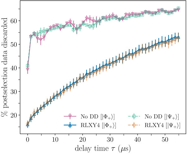
The LDD sequences suppress not only logical errors but physical errors as well. To see this, consider, e.g., the LXX sequence [Fig. 1(d)]. As described in Section III.2.1, reading the pulse sequence vertically, each time step of this sequence operates in the logical subspace as . Simultaneously, reading the sequence horizontally over a complete round of LDD, all four physical qubits undergo the physical XX sequence (i.e., ), which suppresses the set of physical errors . Similarly, for the RLXY4 sequence [Fig. 1(e)], each physical qubit undergoes UR4. which robustly [62] suppresses the sets of physical errors (due to the sequence) and (due to the sequence).
One way to gauge the impact of this suppression of physical errors is shown in Fig. 6, which displays the percentage of discarded data per circuit as a result of postselection over s (out of shots), comparing No DD to RLXY4 for the two logical Bell states and . The results are obtained through bootstrapping across the ten sets of four qubits used in these experiments. Significantly less data are discarded with RLXY4 than without DD. Since discarded data correspond to the detection of physical errors, this means that LDD not only enhances the fidelity of logical Bell states by suppressing logical errors, but also reduces the occurrence of physical errors.
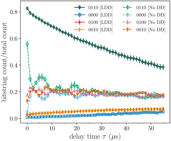
We can go further and use Algorithmic Error Tomography [54] to identify specific physical error types. For example, the and bitstrings correspond, respectively, to physical and errors in the logical Bell state experiment. In Fig. 7 we show the corresponding relative bitstring counts, which are measures of detecting either of these errors. Additionally, we show the and relative bitstring counts, which correspond to the logical fidelity and the logical error, respectively. Without LDD (dashed), we observe that the logical fidelity is low and both logical and physical errors increase and oscillate. With DD (solid), the RLXY4 sequence strongly suppresses both types of errors.
These results demonstrate that, as claimed, LDD sequences suppress both physical and logical errors.
IV Discussion
The operation of QEC codes is adversely affected by the occurrence of logical errors that the code cannot detect or correct. Here, we have shown how to combine QEC with dynamical decoupling implemented in terms of the logical operators of the code, resulting in a hybrid QEC-LDD strategy that is significantly more effective than either QEC or LDD alone.
We designed our LDD sequences to simultaneously perform logical error suppression and to be robust DD sequences at the physical level, resistant to both control errors and crosstalk. Our results, using the code and IBM transmon qubits, demonstrate a beyond-breakeven fidelity of entangled logical qubits.
Our findings address a need along the path toward fault-tolerant quantum computation: keeping codes relatively small and nimble while still effectively handling logical errors.
Future research should aim to optimize LDD sequences tailored to specific codes and integrate QEC-LDD into quantum algorithms. Another interesting future direction is optimization of QEC-LDD for tunable-coupler transmon devices; we present preliminary results in Appendix E.
Acknowledgements.
This material is based upon work supported by, or in part by, the Intelligence Advanced Research Projects Activity (IARPA), under the Entangled Logical Qubits program through Cooperative Agreement Number W911NF23-2-0216, by the U.S. Army Research Laboratory and the U.S. Army Research Office under contract/grant number W911NF2310255, and by the Defense Advanced Research Projects Agency under Agreement HR00112230006. The views, opinions and/or findings expressed are those of the author(s) and should not be interpreted as representing the official views or policies of the Department of Defense or the U.S. Government. This research was conducted using IBM Quantum Systems provided through University of Southern California’s IBM Quantum Innovation Center. The views expressed are those of the authors and do not reflect the official policy or position of IBM or the IBM Quantum team.Appendix A [[4,2,2]] code
The code is an error detection code that encodes logical qubits into physical qubits [102]. The stabilizer group is . Defining the logical states as
| (7) | ||||
a set of logical operators for the code can be defined such that , and , up to multiplication by a stabilizer element. Therefore, we have . Similar definitions apply to the logical operators: and , allowing us to form the full logical Pauli group. Using the same definitions, we have and similarly, , i.e., we can perform logical CNOTs by swapping the physical qubits.
Our particular choice of logical operators is motivated by the fact that and (i.e., the logical operators we use to implement the LDD sequences) have a natural staggering of their physical and gates. In other words, in the implementation of the logical operators comprising LDD, nearest-neighbor qubits are always interleaved with an identity operation (e.g., as opposed to ). This is critical for nearest-neighbor crosstalk cancellation [65].
To encode the logical Bell states and using the two logical qubits of the code, consider:
| (8a) | ||||
| (8b) | ||||
| (8c) | ||||
| (8d) | ||||
Thus, we proceed by preparing two physical copies of the target Bell state on the four physical qubits, then apply , which creates the intended Bell state. The Bell states are prepared similarly.
Appendix B Creating robust logical sequences
As discussed above, we use the logical operators and (along with identity operators) to generate the LDD groups , and . Cycling over the group elements creates the four-pulse sequences LXY4 and LXX shown in the red boxes of Fig. 1(d,e).
Since the main source of logical errors is crosstalk, we optimize LDD so that it cancels such errors. Thus, in the case of LXX, we insert a stabilizer every other pulse-step to consistently apply a staggered sequence to all qubits. These sequences correspond to applying logical and operators to both logical qubits.
To create the robust sequences, we mirror the original sequences (hence the eight-pulse sequences) and instead of and , we apply , respectively, such that each sequence undergoes a robust pulse sequence at the physical level. We also apply staggered physical XY4 to each qubit as shown in Fig. 1(f). This sequence is also inherently robust at the physical level since each qubit receives an XY4 sequence, which is robust to pulse errors [62]. However, it is not a universal decoupling sequence at the logical level, as seen in the figure (i.e., it lacks the ability to decouple arbitrary single logical-qubit errors).
Appendix C The encoding/unencoding Lemma
Encoding of stabilizer codes is a familiar problem [91]. Here we present an explicit version of encoding circuits that appears to be simpler than other versions found in the literature [92, 93].
C.1 Lemma and proof
Lemma 1.
For any stabilizer code it is always possible to construct a unencoding circuit such that converts any group of canonical logical operators and a corresponding stabilizer group into single-qubit Pauli and operators acting just on the first physical data qubits and into single-qubit Pauli stabilizer operators on the remaining ancilla qubits.
Proof.
Our proof is constructive and relies on the basic Clifford group identities and , where denotes the controlled-NOT gate with qubit as the control and qubit as the target. Note that this identity allows us to reduce the number of operators.
Consider first the case .
-
1.
Order the canonical logical operators and stabilizers as .
-
2.
Ensure that consists only of and physical operators: apply and to the qubits where and , respectively, are present in the expression for .
-
3.
Apply SWAP1,j if necessary to ensure is present in the expression for .
-
4.
Apply if necessary to cancel the sign if the sign was .
-
5.
Apply CNOT1,j to eliminate all components of except .
-
6.
Apply analogs of steps 2, 4, and 5 for .
-
7.
Now note that all the other operators contain (indeed, we have , , and all other operators commute with these two, hence they cannot contain , , or ), so the task is reduced to the case with and ; proceed recursively.
Next, consider the case . We have stabilizer operators on physical qubits and wish to transform them to .
-
1.
Apply analogs of previous steps 2-5 to to transform it into .
-
2.
Recursively call this procedure to transform the remaining components of the remaining stabilizers to , …, .
-
3.
Apply CNOT1,j gates to cancel the components of the remaining stabilizers (if they had one). Note that they could not have had or components because otherwise they would not commute with .
-
4.
Apply to cancel the sign of the remaining stabilizers if necessary.
∎
C.2 Illustration using the code
As an example, consider the code. The stabilizer is , and we choose the canonical logical operators as . The corresponding code basis states are
| (9) | ||||
Following the steps in the proof of 1, we obtain the following series of transformations:
| (10) |
where we have only indicated the transformations once, for the operator that induces the transformation per the proof of 1; e.g., is induced by but is applied to every operator in the first timestep, etc.
Thus, the unencoding circuit, i.e., the circuit mapping every logical and stabilizer operator from the code to the corresponding operators of the trivial code, is
| (11) |
where is the Hadamard on the th qubit.
After unencoding, we obtain the trivial code with and , that divides the code into data qubits and ancillas.
In the trivial code, error correction is as follows: apply when and when . Applying to these two recovery operators we find that to correct an undecoupled error in the original code, one should apply whenever and (or , since they are related by a stabilizer element) when .
Appendix D Issues involving the implementation of logical state tomography using the code
A general two-qubit state requires information about expectation values which requires independent measurement settings (achieved by measuring each qubit in three complementary bases; e.g., , , and ) [103]. This holds for logical tomography of a logical two-qubit state as well. There are a few ways in which a logical observable can be measured. First, one can use stabilizer-measurement-like circuits where the logical operator is measured by executing a circuit composed of CNOT gates targeting an ancilla qubit that is measured to learn the logical measurement outcome. This method can further be paired with a round of syndrome extraction using additional ancilla qubits to learn whether the state was in the code space to begin with. This combination of measurements allows us to invoke the code’s protection while simultaneously performing a measurement. The downside of this method is the additional overhead in CNOTs and ancilla qubits needed to perform the measurement protocol. In our case, this would require a substantial overhead in SWAP gates as well since the IBM QPU’s heavy-hex lattice does not pair naturally with the code. Using this logical measurement method would inevitably introduce more errors and reduce the accuracy of logical state tomography.
An alternative, less costly approach for performing logical measurements is to directly measure all data qubits of the code in lieu of introducing ancillas and additional CNOTs. However, this method is incompatible with extracting information about the entire stabilizer generator set while also performing the logical measurement. As a result, we would not be able to know with certainty that the system state was in the code space at the time of measurement. There is some nuance to this approach, which does allow us to learn information about stabilizers which commute qubit-wise (i.e., they share the same Pauli operator or on the same qubit) with the logical operator being measured. For example, we can simultaneously measure , , and the stabilizer since these operators all qubit-wise commute. Performing the measurement of each data qubit in the basis gives us information about each of these logical observables, as well as information about whether or not the system was in the logical code space with respect to the stabilizer generator . Unfortunately, this symmetry does not hold for the operators , , and since these operators do not all commute qubit-wise. This means that we cannot simultaneously learn information about these logical observables and information about whether or not the system was in the code space with respect to the stabilizer in the same shot, reducing our total information about the system. This would lead to a less precise estimation of the logical density matrix, as we will count more experimental shots involving the system outside of the logical state space in our estimation of the logical expectation value.
For these reasons, we did not use logical state tomography in this work.
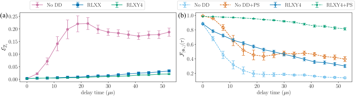
Appendix E Logical dynamical decoupling with tunable couplers
Here we present additional experiments on ibm_marrakesh, which features tunable couplers [104] unlike the always-on interaction in ibm_kyiv. Consequently, for this set of experiments, crosstalk is significantly reduced compared to the other set of results ( kHz vs tens of kHz). Nevertheless, a combination of dephasing and residual crosstalk accumulates, leading to logical errors. Figure 8 illustrates the performance of LDD sequences on this QPU, averaged over 9 different qubit sets. Fig. 8(a) [equivalent to Fig. 3(b)] shows that without DD, logical errors remain unsuppressed. However, both logical DD sequences we employ successfully suppress these errors. Fig. 8(b) [equivalent to Fig. 5(a)] demonstrates that using only postselection, the fidelity averages to , whereas combining postselection with LDD increases it to .
Optimizing LDD for specific types of tunable couplers to maximize the interplay between DD and couplers is an avenue for future work.
References
- Shor [1995] P. W. Shor, Scheme for reducing decoherence in quantum computer memory, Phys. Rev. A 52, R2493 (1995).
- Steane [1996] A. M. Steane, Error correcting codes in quantum theory, Phys. Rev. Lett. 77, 793 (1996).
- Gottesman [1996] D. Gottesman, Class of quantum error-correcting codes saturating the quantum hamming bound, Phys. Rev. A 54, 1862 (1996).
- Calderbank and Shor [1996] A. R. Calderbank and P. W. Shor, Good quantum error-correcting codes exist, Physical Review A 54, 1098 (1996).
- DiVincenzo and Shor [1996] D. P. DiVincenzo and P. W. Shor, Fault-tolerant error correction with efficient quantum codes, Physical Review Letters 77, 3260 (1996).
- D. Aharonov and M. Ben-Or [1997] D. Aharonov and M. Ben-Or, Fault tolerant quantum computation with constant error, in Proceedings of 29th Annual ACM Symposium on Theory of Computing (STOC) (ACM, New York, NY, 1997) p. 176.
- Gottesman [1998] D. Gottesman, Theory of fault-tolerant quantum computation, Physical Review A 57, 127 (1998).
- Knill et al. [1998] E. Knill, R. Laflamme, and W. H. Zurek, Resilient quantum computation, Science 279, 342 (1998).
- Lidar and Brun [2013] D. Lidar and T. Brun, eds., Quantum Error Correction (Cambridge University Press, Cambridge, UK, 2013).
- Campbell et al. [2017] E. T. Campbell, B. M. Terhal, and C. Vuillot, Roads towards fault-tolerant universal quantum computation, Nature 549, 172 EP (2017).
- Cory et al. [1998] D. G. Cory, M. D. Price, W. Maas, E. Knill, R. Laflamme, W. H. Zurek, T. F. Havel, and S. S. Somaroo, Experimental quantum error correction, Phys. Rev. Lett. 81, 2152 (1998).
- Chiaverini et al. [2004] J. Chiaverini, D. Leibfried, T. Schaetz, M. D. Barrett, R. B. Blakestad, J. Britton, W. M. Itano, J. D. Jost, E. Knill, C. Langer, R. Ozeri, and D. J. Wineland, Realization of quantum error correction, Nature 432, 602 (2004).
- Pittman et al. [2005] T. B. Pittman, B. C. Jacobs, and J. D. Franson, Demonstration of quantum error correction using linear optics, Physical Review A 71, 052332 (2005).
- Takita et al. [2017] M. Takita, A. W. Cross, A. D. Córcoles, J. M. Chow, and J. M. Gambetta, Experimental demonstration of fault-tolerant state preparation with superconducting qubits, Physical Review Letters 119, 180501 (2017).
- Harper and Flammia [2019] R. Harper and S. T. Flammia, Fault-tolerant logical gates in the ibm quantum experience, Physical Review Letters 122, 080504 (2019).
- Linke et al. [2017] N. M. Linke, M. Gutierrez, K. A. Landsman, C. Figgatt, S. Debnath, K. R. Brown, and C. Monroe, Fault-tolerant quantum error detection, Science Advances 3, e1701074 (2017).
- Krinner et al. [2022] S. Krinner, N. Lacroix, A. Remm, A. Di Paolo, E. Genois, C. Leroux, C. Hellings, S. Lazar, F. Swiadek, J. Herrmann, G. J. Norris, C. K. Andersen, M. Müller, A. Blais, C. Eichler, and A. Wallraff, Realizing repeated quantum error correction in a distance-three surface code, Nature 605, 669 (2022).
- Google Quantum AI and collaborators [2023] Google Quantum AI and collaborators, Suppressing quantum errors by scaling a surface code logical qubit, Nature 614, 676 (2023).
- Bluvstein et al. [2023] D. Bluvstein, S. J. Evered, A. A. Geim, S. H. Li, H. Zhou, T. Manovitz, S. Ebadi, M. Cain, M. Kalinowski, D. Hangleiter, J. P. Bonilla Ataides, N. Maskara, I. Cong, X. Gao, P. Sales Rodriguez, T. Karolyshyn, G. Semeghini, M. J. Gullans, M. Greiner, V. Vuletić, and M. D. Lukin, Logical quantum processor based on reconfigurable atom arrays, Nature 626, 58 (2023).
- Postler et al. [2024] L. Postler, F. Butt, I. Pogorelov, C. D. Marciniak, S. Heußen, R. Blatt, P. Schindler, M. Rispler, M. Müller, and T. Monz, Demonstration of fault-tolerant steane quantum error correction, PRX Quantum 5, 030326 (2024).
- Google Quantum AI and collaborators [2024a] Google Quantum AI and collaborators, Quantum error correction below the surface code threshold (2024a), arXiv:2408.13687 [quant-ph] .
- Reichardt et al. [2024] B. W. Reichardt, D. Aasen, R. Chao, A. Chernoguzov, W. van Dam, J. P. Gaebler, D. Gresh, D. Lucchetti, M. Mills, S. A. Moses, B. Neyenhuis, A. Paetznick, A. Paz, P. E. Siegfried, M. P. da Silva, K. M. Svore, Z. Wang, and M. Zanner, Demonstration of quantum computation and error correction with a tesseract code (2024), arXiv:2409.04628 [quant-ph] .
- Google Quantum AI and collaborators [2024b] Google Quantum AI and collaborators, Scaling and logic in the color code on a superconducting quantum processor (2024b), arXiv:2412.14256 [quant-ph] .
- Google Quantum AI and collaborators [2024c] Google Quantum AI and collaborators, Demonstrating dynamic surface codes (2024c), arXiv:2412.14360 [quant-ph] .
- Reiher et al. [2017] M. Reiher, N. Wiebe, K. M. Svore, D. Wecker, and M. Troyer, Elucidating reaction mechanisms on quantum computers, Proceedings of the National Academy of Sciences , 201619152 (2017).
- Gidney and Ekera [2021] C. Gidney and M. Ekera, How to factor 2048 bit rsa integers in 8 hours using 20 million noisy qubits, Quantum 5, 433 (2021).
- Dalzell et al. [2023] A. M. Dalzell, S. McArdle, M. Berta, P. Bienias, C.-F. Chen, A. Gilyén, C. T. Hann, M. J. Kastoryano, E. T. Khabiboulline, A. Kubica, G. Salton, S. Wang, and F. G. S. L. Brandão, Quantum algorithms: A survey of applications and end-to-end complexities (2023), arXiv:2310.03011 [quant-ph] .
- Alicki et al. [2006] R. Alicki, D. A. Lidar, and P. Zanardi, Internal consistency of fault-tolerant quantum error correction in light of rigorous derivations of the quantum Markovian limit, Phys. Rev. A 73, 052311 (2006).
- J. Preskill [2013] J. Preskill, Sufficient condition on noise correlations for scalable quantum computing, Quant. Inf. Comput. 13, 181 (2013).
- Clader et al. [2021] B. D. Clader, C. J. Trout, J. P. Barnes, K. Schultz, G. Quiroz, and P. Titum, Impact of correlations and heavy tails on quantum error correction, Physical Review A 103, 052428 (2021).
- Sriram et al. [2024] A. Sriram, N. O’Dea, Y. Li, T. Rakovszky, and V. Khemani, Non-uniform noise rates and griffiths phases in topological quantum error correction (2024), arXiv:2409.03325 [quant-ph] .
- Kam et al. [2024] J. F. Kam, S. Gicev, K. Modi, A. Southwell, and M. Usman, Detrimental non-markovian errors for surface code memory (2024), arXiv:2410.23779 [quant-ph] .
- E. Knill, R. Laflamme [1996] E. Knill, R. Laflamme, Concatenated Quantum Codes (1996), quant-ph/9608012 .
- Aliferis et al. [2006] P. Aliferis, D. Gottesman, and J. Preskill, Quantum accuracy threshold for concatenated distance-3 codes, Quant. Inf. Comput. 6, 97 (2006).
- Dennis et al. [2002] E. Dennis, A. Kitaev, A. Landahl, and J. Preskill, Topological quantum memory, Journal of Mathematical Physics 43, 4452 (2002).
- Fowler et al. [2012] A. G. Fowler, M. Mariantoni, J. M. Martinis, and A. N. Cleland, Surface codes: Towards practical large-scale quantum computation, Phys. Rev. A 86, 032324 (2012).
- Bombin and Martin-Delgado [2006] H. Bombin and M. A. Martin-Delgado, Topological quantum distillation, Physical Review Letters 97, 180501 (2006).
- Breuckmann and Eberhardt [2021] N. P. Breuckmann and J. N. Eberhardt, Quantum low-density parity-check codes, PRX Quantum 2, 040101 (2021).
- Viola and Lloyd [1998] L. Viola and S. Lloyd, Dynamical suppression of decoherence in two-state quantum systems, Phys. Rev. A 58, 2733 (1998).
- Viola et al. [1999] L. Viola, E. Knill, and S. Lloyd, Dynamical decoupling of open quantum systems, Phys. Rev. Lett. 82, 2417 (1999).
- Duan and Guo [1999] L.-M. Duan and G.-C. Guo, Suppressing environmental noise in quantum computation through pulse control, Physics Letters A 261, 139 (1999).
- Vitali and Tombesi [1999] D. Vitali and P. Tombesi, Using parity kicks for decoherence control, Physical Review A 59, 4178 (1999).
- Tripathi et al. [2025] V. Tripathi, N. Goss, A. Vezvaee, L. B. Nguyen, I. Siddiqi, and D. A. Lidar, Qudit dynamical decoupling on a superconducting quantum processor, Phys. Rev. Lett. 134, 050601 (2025).
- Pokharel et al. [2018] B. Pokharel, N. Anand, B. Fortman, and D. A. Lidar, Demonstration of fidelity improvement using dynamical decoupling with superconducting qubits, Phys. Rev. Lett. 121, 220502 (2018).
- Souza [2021] A. M. Souza, Process tomography of robust dynamical decoupling with superconducting qubits, Quantum Information Processing 20, 10.1007/s11128-021-03176-z (2021).
- Ezzell et al. [2023] N. Ezzell, B. Pokharel, L. Tewala, G. Quiroz, and D. A. Lidar, Dynamical decoupling for superconducting qubits: A performance survey, Phys. Rev. Appl. 20, 064027 (2023).
- Tong et al. [2024] C. Tong, H. Zhang, and B. Pokharel, Empirical learning of dynamical decoupling on quantum processors (2024), arXiv:2403.02294 [quant-ph] .
- Seif et al. [2024] A. Seif, H. Liao, V. Tripathi, K. Krsulich, M. Malekakhlagh, M. Amico, P. Jurcevic, and A. Javadi-Abhari, Suppressing correlated noise in quantum computers via context-aware compiling, in 2024 ACM/IEEE 51st Annual International Symposium on Computer Architecture (ISCA) (IEEE, 2024) pp. 310–324.
- Rahman et al. [2024] A. Rahman, D. J. Egger, and C. Arenz, Learning how to dynamically decouple (2024), arXiv:2405.08689 [quant-ph] .
- Arute et al. [2019] F. Arute, K. Arya, R. Babbush, D. Bacon, J. C. Bardin, R. Barends, R. Biswas, S. Boixo, F. G. S. L. Brandao, D. A. Buell, B. Burkett, Y. Chen, Z. Chen, B. Chiaro, R. Collins, W. Courtney, A. Dunsworth, E. Farhi, B. Foxen, A. Fowler, C. Gidney, M. Giustina, R. Graff, K. Guerin, S. Habegger, M. P. Harrigan, M. J. Hartmann, A. Ho, M. Hoffmann, T. Huang, T. S. Humble, S. V. Isakov, E. Jeffrey, Z. Jiang, D. Kafri, K. Kechedzhi, J. Kelly, P. V. Klimov, S. Knysh, A. Korotkov, F. Kostritsa, D. Landhuis, M. Lindmark, E. Lucero, D. Lyakh, S. Mandrà, J. R. McClean, M. McEwen, A. Megrant, X. Mi, K. Michielsen, M. Mohseni, J. Mutus, O. Naaman, M. Neeley, C. Neill, M. Y. Niu, E. Ostby, A. Petukhov, J. C. Platt, C. Quintana, E. G. Rieffel, P. Roushan, N. C. Rubin, D. Sank, K. J. Satzinger, V. Smelyanskiy, K. J. Sung, M. D. Trevithick, A. Vainsencher, B. Villalonga, T. White, Z. J. Yao, P. Yeh, A. Zalcman, H. Neven, and J. M. Martinis, Quantum supremacy using a programmable superconducting processor, Nature 574, 505 (2019).
- Jurcevic et al. [2021] P. Jurcevic, A. Javadi-Abhari, L. S. Bishop, I. Lauer, D. F. Bogorin, M. Brink, L. Capelluto, O. Günlük, T. Itoko, N. Kanazawa, A. Kandala, G. A. Keefe, K. Krsulich, W. Landers, E. P. Lewandowski, D. T. McClure, G. Nannicini, A. Narasgond, H. M. Nayfeh, E. Pritchett, M. B. Rothwell, S. Srinivasan, N. Sundaresan, C. Wang, K. X. Wei, C. J. Wood, J.-B. Yau, E. J. Zhang, O. E. Dial, J. M. Chow, and J. M. Gambetta, Demonstration of quantum volume 64 on a superconducting quantum computing system, Quantum Sci. Technol. 6, 025020 (2021).
- Bäumer et al. [2024] E. Bäumer, V. Tripathi, D. S. Wang, P. Rall, E. H. Chen, S. Majumder, A. Seif, and Z. K. Minev, Efficient long-range entanglement using dynamic circuits, PRX Quantum 5, 030339 (2024).
- Pokharel and Lidar [2023] B. Pokharel and D. A. Lidar, Demonstration of algorithmic quantum speedup, Phys. Rev. Lett. 130, 210602 (2023).
- Pokharel and Lidar [2024] B. Pokharel and D. Lidar, Better-than-classical grover search via quantum error detection and suppression, npj Quantum Information 10, 10.1038/s41534-023-00794-6 (2024).
- Singkanipa et al. [2024] P. Singkanipa, V. Kasatkin, Z. Zhou, G. Quiroz, and D. A. Lidar, Demonstration of algorithmic quantum speedup for an abelian hidden subgroup problem (2024), arXiv:2401.07934 [quant-ph] .
- Bäumer et al. [2024] E. Bäumer, V. Tripathi, A. Seif, D. Lidar, and D. S. Wang, Quantum fourier transform using dynamic circuits (2024), arXiv:2403.09514 [quant-ph] .
- Ng et al. [2011] H. K. Ng, D. A. Lidar, and J. Preskill, Combining dynamical decoupling with fault-tolerant quantum computation, Phys. Rev. A 84, 012305 (2011).
- Paz-Silva and Lidar [2013] G. A. Paz-Silva and D. A. Lidar, Optimally combining dynamical decoupling and quantum error correction, Scientific Reports 3, 10.1038/srep01530 (2013).
- Goto et al. [2023] H. Goto, Y. Ho, and T. Kanao, Measurement-free fault-tolerant logical-zero-state encoding of the distance-three nine-qubit surface code in a one-dimensional qubit array, Phys. Rev. Res. 5, 043137 (2023).
- Han et al. [2024] J.-X. Han, J. Zhang, G.-M. Xue, H. Yu, and G. Long, Protecting logical qubits with dynamical decoupling (2024), arXiv:2402.05604 [quant-ph] .
- Quiroz and Lidar [2013] G. Quiroz and D. A. Lidar, Optimized dynamical decoupling via genetic algorithms, Phys. Rev. A 88, 052306 (2013).
- Genov et al. [2017] G. T. Genov, D. Schraft, N. V. Vitanov, and T. Halfmann, Arbitrarily accurate pulse sequences for robust dynamical decoupling, Phys. Rev. Lett. 118, 133202 (2017).
- Wocjan [2006] P. Wocjan, Efficient decoupling schemes with bounded controls based on eulerian orthogonal arrays, Physical Review A 73, 062317 (2006).
- Tripathi et al. [2022] V. Tripathi, H. Chen, M. Khezri, K.-W. Yip, E. Levenson-Falk, and D. A. Lidar, Suppression of crosstalk in superconducting qubits using dynamical decoupling, Phys. Rev. Appl. 18, 024068 (2022).
- Zhou et al. [2023] Z. Zhou, R. Sitler, Y. Oda, K. Schultz, and G. Quiroz, Quantum crosstalk robust quantum control, Phys. Rev. Lett. 131, 210802 (2023).
- Evert et al. [2024] B. Evert, Z. G. Izquierdo, J. Sud, H.-Y. Hu, S. Grabbe, E. G. Rieffel, M. J. Reagor, and Z. Wang, Syncopated dynamical decoupling for suppressing crosstalk in quantum circuits (2024), arXiv:2403.07836 [quant-ph] .
- Brown and Lidar [2024] A. F. Brown and D. A. Lidar, Efficient chromatic-number-based multi-qubit decoherence and crosstalk suppression (2024), arXiv:2406.13901 .
- Knill and Laflamme [1997] E. Knill and R. Laflamme, Theory of quantum error-correcting codes, Phys. Rev. A 55, 900 (1997).
- Ku et al. [2020] J. Ku, X. Xu, M. Brink, D. C. McKay, J. B. Hertzberg, M. H. Ansari, and B. L. T. Plourde, Suppression of unwanted interactions in a hybrid two-qubit system, Phys. Rev. Lett. 125, 200504 (2020).
- Wei et al. [2022] K. X. Wei, E. Magesan, I. Lauer, S. Srinivasan, D. F. Bogorin, S. Carnevale, G. A. Keefe, Y. Kim, D. Klaus, W. Landers, N. Sundaresan, C. Wang, E. J. Zhang, M. Steffen, O. E. Dial, D. C. McKay, and A. Kandala, Hamiltonian engineering with multicolor drives for fast entangling gates and quantum crosstalk cancellation, Physical Review Letters 129, 060501 (2022).
- Zanardi [1999] P. Zanardi, Symmetrizing evolutions, Physics Letters A 258, 77 (1999).
- Zanardi [2000] P. Zanardi, Stabilizing quantum information, Physical Review A 63, 012301 (2000).
- Maudsley [1986] A. A. Maudsley, Modified carr-purcell-meiboom-gill sequence for nmr fourier imaging applications, Journal of Magnetic Resonance (1969) 69, 488 (1986).
- Khodjasteh and Lidar [2005] K. Khodjasteh and D. A. Lidar, Fault-tolerant quantum dynamical decoupling, Physical Review Letters 95, 180501 (2005).
- Uhrig [2007] G. S. Uhrig, Keeping a quantum bit alive by optimized -pulse sequences, Phys. Rev. Lett. 98, 100504 (2007).
- West et al. [2010] J. R. West, B. H. Fong, and D. A. Lidar, Near-optimal dynamical decoupling of a qubit, Phys. Rev. Lett. 104, 130501 (2010).
- Wang and Liu [2011] Z.-Y. Wang and R.-B. Liu, Protection of quantum systems by nested dynamical decoupling, Phys. Rev. A 83, 022306 (2011).
- Xia et al. [2011] Y. Xia, G. S. Uhrig, and D. A. Lidar, Rigorous performance bounds for quadratic and nested dynamical decoupling, Phys. Rev. A 84, 062332 (2011).
- Gough and Nurdin [2017] J. E. Gough and H. I. Nurdin, Can quantum markov evolutions ever be dynamically decoupled?, in 2017 IEEE 56th Annual Conference on Decision and Control (CDC) (2017) pp. 6155–6160.
- Szczygielski and Alicki [2015] K. Szczygielski and R. Alicki, Markovian theory of dynamical decoupling by periodic control, Physical Review A 92, 022349 (2015).
- Addis et al. [2015] C. Addis, F. Ciccarello, M. Cascio, G. M. Palma, and S. Maniscalco, Dynamical decoupling efficiency versus quantum non-markovianity, New Journal of Physics 17, 123004 (2015).
- Arenz et al. [2018] C. Arenz, D. Burgarth, P. Facchi, and R. Hillier, Dynamical decoupling of unbounded hamiltonians, Journal of Mathematical Physics, Journal of Mathematical Physics 59, 032203 (2018).
- Mozgunov and Lidar [2020] E. Mozgunov and D. Lidar, Completely positive master equation for arbitrary driving and small level spacing, Quantum 4, 227 (2020).
- Khodjasteh and Lidar [2003] K. Khodjasteh and D. A. Lidar, Quantum computing in the presence of spontaneous emission by a combined dynamical decoupling and quantum-error-correction strategy, Physical Review A 68, 022322 (2003), erratum: ibid, Phys. Rev. A 72, 029905 (2005).
- Aliferis et al. [2009] P. Aliferis, F. Brito, D. P. DiVincenzo, J. Preskill, M. Steffen, and B. M. Terhal, Fault-tolerant computing with biased-noise superconducting qubits: a case study, New Journal of Physics 11, 013061 (2009).
- Bonilla Ataides et al. [2021] J. P. Bonilla Ataides, D. K. Tuckett, S. D. Bartlett, S. T. Flammia, and B. J. Brown, The xzzx surface code, Nature Communications 12, 2172 (2021).
- Viola et al. [2000] L. Viola, E. Knill, and S. Lloyd, Dynamical generation of noiseless quantum subsystems, Phys. Rev. Lett. 85, 3520 (2000).
- Byrd and Lidar [2002] M. S. Byrd and D. A. Lidar, Comprehensive encoding and decoupling solution to problems of decoherence and design in solid-state quantum computing, Phys. Rev. Lett. 89, 047901 (2002).
- Lidar [2008] D. A. Lidar, Towards fault tolerant adiabatic quantum computation, Phys. Rev. Lett. 100, 160506 (2008).
- Quiroz et al. [2024] G. Quiroz, B. Pokharel, J. Boen, L. Tewala, V. Tripathi, D. Williams, L.-A. Wu, P. Titum, K. Schultz, and D. Lidar, Dynamically generated decoherence-free subspaces and subsystems on superconducting qubits, Reports on Progress in Physics 87, 097601 (2024).
- D. Gottesman [1997] D. Gottesman, Stabilizer Codes and Quantum Error Correction, Ph.D. thesis, California Institute of Technology, Pasadena, CA (1997), quant-ph/9705052 .
- Cleve and Gottesman [1997] R. Cleve and D. Gottesman, Efficient computations of encodings for quantum error correction, Physical Review A 56, 76 (1997).
- Higgott et al. [2021] O. Higgott, M. Wilson, J. Hefford, J. Dborin, F. Hanif, S. Burton, and D. E. Browne, Optimal local unitary encoding circuits for the surface code, Quantum 5, 517 (2021).
- McKay et al. [2017] D. C. McKay, C. J. Wood, S. Sheldon, J. M. Chow, and J. M. Gambetta, Efficient gates for quantum computing, Physical Review A 96, 022330 (2017).
- Vezvaee et al. [2024] A. Vezvaee, V. Tripathi, D. Kowsari, E. Levenson-Falk, and D. A. Lidar, Virtual z gates and symmetric gate compilation (2024), arXiv:2407.14782 [quant-ph] .
- [96] IBM Quantum.
- Koch et al. [2007] J. Koch, T. M. Yu, J. Gambetta, A. A. Houck, D. I. Schuster, J. Majer, A. Blais, M. H. Devoret, S. M. Girvin, and R. J. Schoelkopf, Charge-insensitive qubit design derived from the Cooper pair box, Physical Review A 76, 042319 (2007).
- Blais et al. [2021] A. Blais, A. L. Grimsmo, S. M. Girvin, and A. Wallraff, Circuit quantum electrodynamics, Rev. Mod. Phys. 93, 025005 (2021).
- Tripathi et al. [2024] V. Tripathi, D. Kowsari, K. Saurav, H. Zhang, E. M.Levenson-Falk, and D. A. Lidar, Benchmarking quantum gates and circuits (2024), arXiv:2407.09942 [quant-ph] .
- Zhang et al. [2024] J. Zhang, Z.-Y. Chen, Y.-J. Wang, B.-H. Lu, H.-F. Zhang, J.-N. Li, P. Duan, Y.-C. Wu, and G.-P. Guo, Demonstrating a universal logical gate set in error-detecting surface codes on a superconducting quantum processor (2024), arXiv:2405.09035 [quant-ph] .
- Hetényi and Wootton [2024] B. Hetényi and J. R. Wootton, Creating entangled logical qubits in the heavy-hex lattice with topological codes, PRX Quantum 5, 040334 (2024).
- Vaidman et al. [1996] L. Vaidman, L. Goldenberg, and S. Wiesner, Error prevention scheme with four particles, Physical Review A 54, R1745 (1996).
- James et al. [2001] D. F. V. James, P. G. Kwiat, W. J. Munro, and A. G. White, Measurement of qubits, Physical Review A 64, 052312 (2001).
- Stehlik et al. [2021] J. Stehlik, D. M. Zajac, D. L. Underwood, T. Phung, J. Blair, S. Carnevale, D. Klaus, G. A. Keefe, A. Carniol, M. Kumph, M. Steffen, and O. E. Dial, Tunable coupling architecture for fixed-frequency transmon superconducting qubits, Phys. Rev. Lett. 127, 080505 (2021).