Surface-state engineering for nonlinear charge and spin photocurrent generation
Abstract
We systematically explore a pathway for generating nonlinear charge and spin photocurrents using spin-orbit-split surface states. This mechanism enables net charge and spin flow along the surface plane even in centrosymmetric bulk environments like the Rashba prototype Au(111), where we establish the key principles by combining model predictions with density functional calculations. We further identify the Tl/Si(111) surface, characterized by strong non-Rashba spin-orbit coupling, as a prime candidate for experimental validation; with slight doping, it develops metallic spin-orbit-split states featuring remarkable relativistic properties while the bulk remains semiconducting. Our non-linear simulations reveal distinct angular signatures and magnitudes comparable to bulk ferroelectrics, highlighting the potential of surface-state photocurrents for low-bias optoelectronic applications. Moreover, the intricate spin polarization of surface states opens new possibilities as a nonlinear spin filter, providing a far more versatile platform than the spin Hall effect.
Materials that lack a center of inversion in their crystalline structure exhibit a distinctive optical effect known as the bulk photovoltaic effect (BVPE) [1, 2, 3]. This phenomenon is described by a quadratic optical response that generates a net DC photocurrent in homogeneous materials. The effect has enormous potential for applications in interface-free solar cell technologies, which represents a notable advantage over the standard photovoltaics based on pn junctions. In recent years, materials such as Weyl semimetals [4, 5] or transition-metal dichalcogenide nanotubes [6, 7] have exhibited a striking enhancement of the BVPE, approaching competitive figures of merit. In addition, recent works suggest that the spin-dependent counterpart of the effect [8] might pave the way for novel applications, e.g. as pure spin current generators [9] or as a knob of unconventional magnetic phases [10].
A significant challenge in identifying materials with an enhanced BVPE is the necessity of broken inversion symmetry, which greatly limits the pool of viable candidates. However, even in bulk centrosymmetric materials inversion symmetry is inherently broken at their surface, enabling symmetry-allowed quadratic optical responses [11, 12]. In this scenario, the nonlinear response is expected to be most prominent in states highly localized around the surface, particularly in electronic transitions involving surface states. Given the strong ties between surface states and relativistic effects such as the spin-orbit interaction, this approach provides an excellent platform to explore the influence of spin-orbit physics on nonlinear optical absorption.
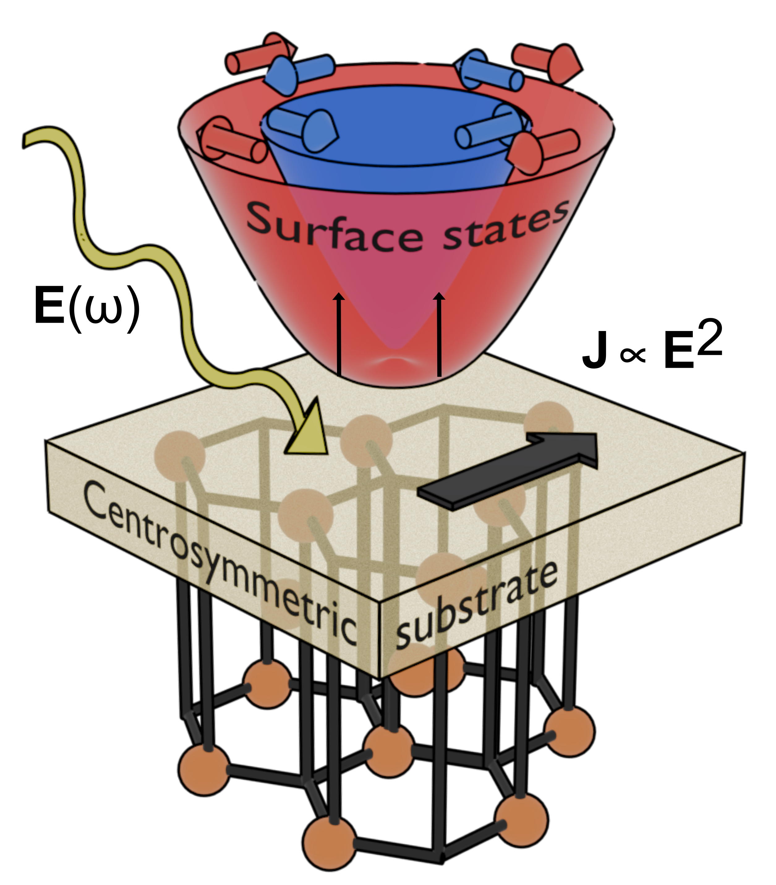
In this study, we provide a quantitative investigation of nonlinear photocurrents generated by spin-orbit split surface states. As illustrated in Fig. 1, this mechanism enables a net DC charge and spin flow along the surface plane, even within a bulk environment that maintains centrosymmetry. Despite the appeal of such mechanism, previous theoretical studies have been limited to the specific context of surface states in topological insulators and explored solely at the model level [13, 14]. Here, we substantiate our findings through density functional theory (DFT) calculations, offering realistic estimates for spin and charge photocurrent magnitudes in specific materials. First, we establish the fundamental principles in the Au(111) surface featuring the prototype Rashba spin-orbit split states as sketched in Fig. 1. Next, we identify Tl/Si(111) as an ideal candidate for experimental realization, providing clear and measurable signatures of surface-state charge photocurrents. Finally, we demonstrate that its unique surface-state spin-polarization structure near the K and K′ valleys provides the system with the functionality of a nonlinear spin filter.
We begin by describing the quadratic optical contributions to the BVPE. Under a monochromatic light field , the generated DC charge photocurrent () has two sources, namely the shift and injection currents. In a time-reversal invariant material, it can be written as
| (1) |
with , and Cartesian indexes. In Eq. (1), and stand for the shift and injection photoconductivities, respectively. The former describes an intrinsic contribution to the current originating from real-space shifts undergone by electrons upon photoexcitation, which is symmetric in the electric field indexes. In contrast, is anti-symmetric in , and its generation rate is proportional to the electronic relaxation time . These contributions were intensively studied a few decades ago [1, 2, 3], and their modern length-gauge expressions employed in this work were derived in Ref. [15] (see more details in the Supporting Information [16]).
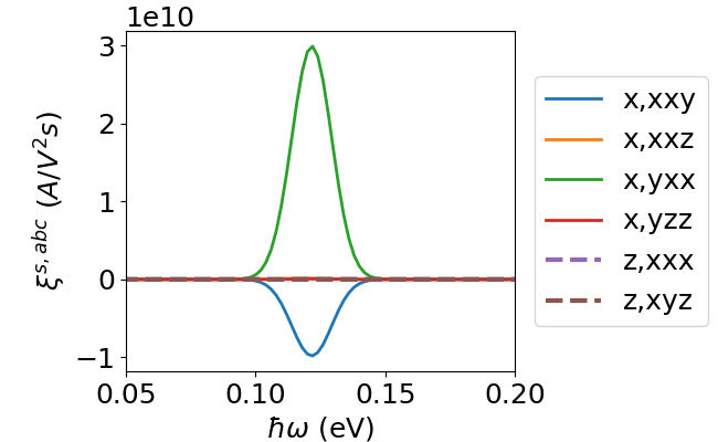
As a specific material realization, we first consider Au(111), a system where Lashell et al. famously reported evidence of spin-split surface states driven by spin-orbit coupling [17]. Since then, it has become a paradigmatic example of the Rashba two-dimensional electron gas [18, 19, 20]. Fig. 1 pictorially depicts the band structure near the point, highlighting its characteristic spin-orbit splitting and the purely in-plane spin texture. Unlike bulk Au, Au(111) belongs to the noncentrosymmetric point group 3m, enabling symmetry-allowed quadratic optical responses at the surface. Table 1 displays the permitted (independent) components which can generate current under linearly polarized light (LPL) and circularly polarized light (CPL) by the quadratic shift and injection mechanisms.
| LPL | CPL | |
| Charge shift | ||
| Charge injection | ||
| Spin shift | , , | |
| Spin injection | , , , | |
| , , |
We focus on excitations that connect the spin-orbit split surface states of Au(111) (see Fig. 1) and employ the Rashba model to gain insight into the underlying physical properties. At linear order in the crystal momentum , the Rashba model is isotropic. However, it can be extended with higher-order terms that comply with specific point group symmetries. In this work, we incorporate terms up to third order in that transform according to the noncentrosymmetric point group of Au(111), as originally proposed in Ref. [21]. The Hamiltonian in polar coordinates () reads
| (2) |
It is composed by the isotropic linear term characterized by the Rashba coupling constant , a third order isotropic correction with coefficient , and the hexagonal warping term characterized by [21]. The inclusion of hexagonal warping is essential to break the symmetry of the otherwise isotropic low energy Hamiltonian, allowing in-plane surface currents. Since for Au(111) the Rashba model is only valid in a small region close to the point, we treat terms as a perturbation. The transition matrix elements of the shift and injection photocurrents can be readily calculated (see SI for details and the complete list of photoconductivity components):
| (3) | ||||
| (4) |
Note that only yields a finite response whereas the rest integrate to zero in -space, in accordance with Table 1. Besides predicting a simple polar distribution for all contributions, Eqs. (3)-(4) clearly highlight the importance of the warping term for a finite quadratic response. This is in line with Refs. [13, 14], which employed the model in the context of topological insulators.
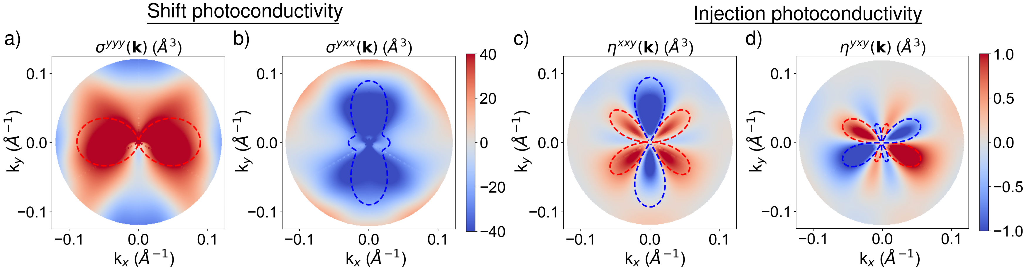
Having described the basic features by means of the Rashba model, we now move to analyze quantitative results. To this end, we have performed fully-relativistic DFT calculations for Au(111) using the Quantum ESPRESSO package [22, 23] and computed the nonlinear optical properties by means of a Wannier interpolation technique [24, 25] (see SI for details). Fig. 2 presents a k-resolved map of the calculated transition probabilities around , along with the Rashba model predictions overlaid for comparison. In the case of injection [Figs. 2c,d], the ab initio results match remarkably well the model predictions, both in the multi-lobe pattern form as well as in the sign. In comparison, the Rashba model performs worse in the qualitative description of the shift photocurrent, as evidenced by Figs. 2a,b. This difference is likely due to the sensitivity of the shift mechanism to the quantum-geometric properties of the Bloch wavefunction entering in the expression of [15], which are not captured completely in two-band models [26].
Our results for Au(111) highlight the fundamental features of quadratic photoresponses driven by Rashba surface states, and open up the possibility of extracting the hexagonal warping constant through optical measurements of the symmetry-allowed shift component . However, the metallic nature of bulk Au states might present a practical challenge for such purpose due to hybridization with the surface Rashba bands. Consequently, we now shift our focus to the Tl/Si(111) surface, whose electronic properties are also prominently influenced by the spin-orbit interaction and possesses important advantages over Au(111). Firstly, due to the the material’s semiconducting nature, the surface response remains well-isolated and distinguishable from any bulk current contribution [27]. Secondly, it hosts a pair of unoccupied spin-split surface states, as shown in Fig 3, which in experiment can be populated at the K, K’ valleys under slight electron doping without affecting bulk states, thus being extremely robust [28]. Thirdly, these surface states exhibit a huge spin-orbit splitting of eV — a value well-suited for optical applications — accompanied by an out-of-plane spin polarization at the K and K’ valleys, completely deviating from the Rashba model properties [29, 30].
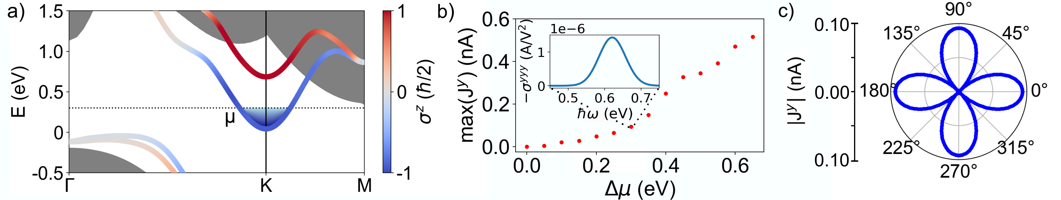
We have performed ab-initio calculations for the Tl/Si(111) surface following the same procedure as described earlier for Au(111) (see SI for computational details). As Tl/Si(111) belongs to the point group, the allowed photoconductivity components are also contained in Table 1. We therefore focus on the symmetry-allowed shift component associated to transitions between the spin-orbit split surface states indicated in Fig. 3a, where the lowest band can be populated by electron doping.
The inset in Fig. 3b shows that for a moderate doping level of eV, the shift current is largest around eV with maximum A/V2. Notably, as a central result of this manuscript, the surface-state photoconductivity translates into a measurable in-plane photocurrent. This is proven in main Fig. 3b, where we illustrate how the maximum of at photon frequency eV behaves as a function of doping level. The calculations account for relevant factors such as reflection, absorption based on the Glass coefficient [31, 32], and the parameters of the external optical field, which were selected to align with those commonly used in current experiments [4] (see SI). At doping levels ranging from 0 to eV, we observe that the nonlinear shift photocurrent flowing along the surface plane is large, comparable to values reported in prototypic bulk materials like [33]. In addition to the magnitude, in Fig. 3c we analyze the angular dependence of the photocurrent as a function of the light polarization in the -plane. We find that the current is maximized along the crystallographic and axes, whereas it vanishes at angles. This provides a clear signature, different from any potential linear contribution, for experimental detection of pure surface-state shift photocurrents.
In the remaining part of the manuscript, we extend our study to the spin photocurrent contribution, thereby completing the description of surface-state-driven effects. Nonlinear spin photocurrents have received significantly less attention than the charge counterparts, with notable progress emerging only recently [13, 34, 8]. In this work, we adopt the formalism established by Lihm and Park [8], where transition matrix elements associated to the spin shift and injection currents are naturally suited for Wannier interpolation techniques (see SI).
Table 1 lists the symmetry-allowed spin shift and injection tensor components for Au(111) and Tl/Si(111). As sketched in Fig. 4a, these mechanism provide a remarkable spin-filtering functionality; they can generate a DC spin current that is spin-polarized along the out-of-plane direction ( components) or in-plane directions depending on the polarization of light. From the standpoint of symmetry alone, both Au(111) and Tl/Si(111) possess such functionality. In practice, however, our DFT calculations show that Au(111) generates negligible out-of-plane spin current, which is a direct consequence of the purely in-plane spin texture of its surface states (see SI).
In contrast, DFT calculations show that Tl/Si(111) presents both in-plane and out-of-plane spin-polarized photocurrents. As surface states are spin-polarized in k-space near the band edge, it is particularly relevant to analyze how the spin texture influences both the form and magnitude of the nonlinear spin photoconductivity. In Fig. 4b we present the -resolved contributions for both in-plane and out-of-plane spin injection components, symmetrized to preserve the relevant crystal symmetries. For small doping levels, we find that the out-of-plane components within the K, K’ valleys (top panel) are substantially larger than the in-plane components (bottom panel). The dominant contribution arises through the component , while in-plane components such as are significantly smaller. The latter become larger in other regions of the Brillouin zone, but are energetically accessible only for far larger doping levels eV. Thus, in practice, Tl/Si(111) acts as a spin injector/filter as a function of doping, generating spin-polarized currents with a well-defined out-of-plane spin component () for eV. This is rather remarkable, given that the spin is not a good quantum number of this system due to its strong relativistic effects.
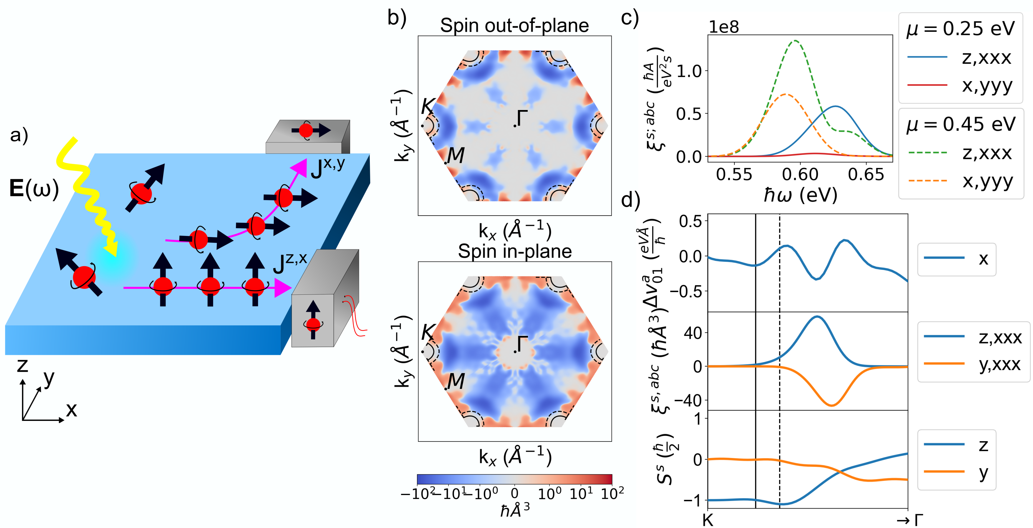
To further illustrate this feature of the Tl/Si(111) surface, Fig. 4c presents the dominant integrated components of the spin injection tensor and , for two representative values of the chemical potential, and eV. At eV, the spin injection is predominantly governed by the out-of-plane component, whereas at eV, the in-plane contribution becomes quantitatively relevant. In order to understand the origin of these results, in Fig. 4d we display the k-resolved structure of several relevant quantities along the high-symmetry path , where we mark the Fermi surface cuts for the two doping levels and 0.45 eV. We begin by considering the top panel, which displays the difference of velocity matrix elements entering the expression of the spin injection contribution (see SI). Since both surface states exhibit a band minimum at K (see Fig. 3a), this quantity remains very small near this valley. As a result, the two spin injection contributions and , shown in the middle panel of Fig. 4d are also very small in this region, with both peaking away from K. Note that these components are not the same as in Fig. 4c, the ones considered in Fig. 4d differ only in the spin index for comparative purposes. Notably, the origin of the strong out-of-plane peak can be traced back to the out-of-plane spin-polarization of the surface states, illustrated in the lower panel of Fig. 4d. A comparison with the middle panel reveals that the spin injection component peaks in the region where dominates, whereas the component peaks only when becomes significantly smaller. This highlights the crucial role of the out-of-plane spin polarization – completely absent in Au(111) – in generating a pure out-of-plane nonlinear spin current in Tl/Si(111).
In summary, we have presented a detailed study of nonlinear photocurrents arising from spin-orbit split surface states. Besides elucidating the fundamental aspects of the effect in the Rashba prototype Au(111) surface, we have identified an optimal platform for experimental detection in the Tl/Si(111) surface. Our calculations have shown that the magnitude of the generated bulk photovoltaic effect is well within the measurable limits, and we have provided clear angular fingerprints for its detection. While we have focused on Tl/Si(111), our proposal is general given that it does not require inversion-symmetry breaking of the bulk substrate, hence we expect similar features in other heavily studied compounds made of Bi, Pb or Ag [35, 36]. Additionally, we have explored the nonlinear spin counterpart of this effect, demonstrating that Tl/Si(111) functions as an exceptionally effective spin filter, with its performance tunable through doping. Notably, nonlinear spin currents provide far greater flexibility than the conventional linear approach, which is limited by the lower dimensionality of the spin Hall conductivity tensor and only permits transverse spin accumulation [37, 38, 39]. The interplay between spin texture and nonlinear responses paves the way for novel strategies in engineering spatial- and spin-selective nonlinear spin generation, offering enhanced control and tunability for spintronic applications.
J. S., P. G.-G. and J. I. A. acknowledge the financial support of the European Union’s Horizon 2020 research and innovation programme under the European Research Council (ERC) grant agreement No. 946629 StG PhotoNow. D. H.-P. is grateful for funding from the Diputación Foral de Gipuzkoa through Grants 2023-FELL-000002-01, 2024-FELL-000009-01. D.H.-P. and J. I.-A. are also grateful from support of the Spanish MICIU/AEI/10.13039/501100011033 through Project No. PID2023-147324NA-I00.
References
- Belinicher et al. [1982] V. I. Belinicher, E. L. Ivchenko, and B. I. Sturman, Kinetic theory of the displacement photovoltaic effect in piezoelectrics, Sov. Phys. JETP 56, 359 (1982).
- Sturman and Fridkin [1992] B. I. Sturman and V. M. Fridkin, The photovoltaic and photorefractive effects in noncentrosymmetric materials (Gordon and Breach, 1992).
- von Baltz and Kraut [1981] R. von Baltz and W. Kraut, Theory of the bulk photovoltaic effect in pure crystals, Phys. Rev. B 23, 5590 (1981).
- Ma et al. [2019] J. Ma, Q. Gu, Y. Liu, J. Lai, P. Yu, X. Zhuo, Z. Liu, J.-H. Chen, J. Feng, and D. Sun, Nonlinear photoresponse of type-II Weyl semimetals, Nature Materials 18, 476 (2019).
- Osterhoudt et al. [2019] G. B. Osterhoudt, L. K. Diebel, M. J. Gray, X. Yang, J. Stanco, X. Huang, B. Shen, N. Ni, P. J. Moll, Y. Ran, et al., Colossal mid-infrared bulk photovoltaic effect in a type-I Weyl semimetal, Nature Materials 18, 471 (2019).
- Zhang et al. [2019] Y. J. Zhang, T. Ideue, M. Onga, F. Qin, R. Suzuki, A. Zak, R. Tenne, J. H. Smet, and Y. Iwasa, Enhanced intrinsic photovoltaic effect in tungsten disulfide nanotubes, Nature 570, 349 (2019).
- Krishna et al. [2023] J. Krishna, P. Garcia-Goiricelaya, F. de Juan, and J. Ibañez-Azpiroz, Understanding the large shift photocurrent of WS2 nanotubes: A comparative analysis with monolayers, Phys. Rev. B 108, 165418 (2023).
- Lihm and Park [2022] J.-M. Lihm and C.-H. Park, Comprehensive theory of second-order spin photocurrents, Phys. Rev. B 105, 045201 (2022).
- Xu et al. [2021a] H. Xu, H. Wang, J. Zhou, and J. Li, Pure spin photocurrent in non-centrosymmetric crystals: bulk spin photovoltaic effect, Nature Communications 12, 4330 (2021a), publisher: Nature Publishing Group.
- Dong et al. [2024] R. Dong, R. Cao, D. Tan, and R. Fei, Crystal symmetry selected pure spin photocurrent in altermagnetic insulators (2024), arXiv:2412.09216 [cond-mat.mtrl-sci] .
- Arzate et al. [2014] N. Arzate, R. A. Vázquez-Nava, and B. S. Mendoza, Optical spin- and current-injection study on Si(111)-In surfaces, Phys. Rev. B 90, 205310 (2014).
- Cabellos et al. [2011] J. L. Cabellos, B. S. Mendoza, and A. I. Shkrebtii, Optical coherent current control at surfaces: Theory of injection current, Phys. Rev. B 84, 195326 (2011).
- Kim et al. [2017] K. W. Kim, T. Morimoto, and N. Nagaosa, Shift charge and spin photocurrents in Dirac surface states of topological insulator, Phys. Rev. B 95, 035134 (2017).
- Leppenen and Golub [2023] N. V. Leppenen and L. E. Golub, Linear photogalvanic effect in surface states of topological insulators, Phys. Rev. B 107, L161403 (2023).
- Sipe and Shkrebtii [2000] J. E. Sipe and A. I. Shkrebtii, Second-order optical response in semiconductors, Phys. Rev. B 61, 5337 (2000).
- [16] See supplementary material for additional information of the charge and spin photonconductivity expression, model and material calculations .
- LaShell et al. [1996] S. LaShell, B. A. McDougall, and E. Jensen, Spin splitting of an Au(111) surface state band observed with angle resolved photoelectron spectroscopy, Phys. Rev. Lett. 77, 3419 (1996).
- Heide et al. [2006] M. Heide, G. Bihlmayer, P. Mavropoulos, A. Bringer, and S. Blügel, Psi-k Newsletter 78, 1109 (2006).
- Henk et al. [2004] J. Henk, M. Hoesch, J. Osterwalder, A. Ernst, and P. Bruno, Journal of Physics: Condensed Matter 16, 7581 (2004).
- Ibañez-Azpiroz et al. [2013] J. Ibañez-Azpiroz, A. Bergara, E. Y. Sherman, and A. Eiguren, Spin-flip transitions and departure from the Rashba model in the Au(111) surface, Phys. Rev. B 88, 125404 (2013).
- Fu [2009] L. Fu, Hexagonal warping effects in the surface states of the topological insulator Bi2Te3, Phys. Rev. Lett. 103, 266801 (2009).
- Giannozzi et al. [2009] P. Giannozzi, S. Baroni, N. Bonini, M. Calandra, R. Car, C. Cavazzoni, D. Ceresoli, G. L. Chiarotti, M. Cococcioni, I. Dabo, A. Dal Corso, S. de Gironcoli, S. Fabris, G. Fratesi, R. Gebauer, U. Gerstmann, C. Gougoussis, A. Kokalj, M. Lazzeri, L. Martin-Samos, N. Marzari, F. Mauri, R. Mazzarello, S. Paolini, A. Pasquarello, L. Paulatto, C. Sbraccia, S. Scandolo, G. Sclauzero, A. P. Seitsonen, A. Smogunov, P. Umari, and R. M. Wentzcovitch, QUANTUM ESPRESSO: a modular and open-source software project for quantum simulations of materials, Journal of Physics: Condensed Matter 21, 395502 (2009).
- Giannozzi et al. [2017] P. Giannozzi, O. Andreussi, T. Brumme, O. Bunau, M. Buongiorno Nardelli, M. Calandra, R. Car, C. Cavazzoni, D. Ceresoli, M. Cococcioni, N. Colonna, I. Carnimeo, A. Dal Corso, S. de Gironcoli, P. Delugas, R. A. DiStasio, A. Ferretti, A. Floris, G. Fratesi, G. Fugallo, R. Gebauer, U. Gerstmann, F. Giustino, T. Gorni, J. Jia, M. Kawamura, H.-Y. Ko, A. Kokalj, E. Küçükbenli, M. Lazzeri, M. Marsili, N. Marzari, F. Mauri, N. L. Nguyen, H.-V. Nguyen, A. Otero-de-la Roza, L. Paulatto, S. Poncé, D. Rocca, R. Sabatini, B. Santra, M. Schlipf, A. P. Seitsonen, A. Smogunov, I. Timrov, T. Thonhauser, P. Umari, N. Vast, X. Wu, and S. Baroni, Advanced capabilities for materials modelling with Quantum ESPRESSO, Journal of Physics: Condensed Matter 29, 465901 (2017).
- Ibañez-Azpiroz et al. [2018] J. Ibañez-Azpiroz, S. S. Tsirkin, and I. Souza, Ab initio calculation of the shift photocurrent by Wannier interpolation, Phys. Rev. B 97, 245143 (2018).
- Puente-Uriona et al. [2023] A. R. Puente-Uriona, S. S. Tsirkin, I. Souza, and J. Ibañez-Azpiroz, Ab initio study of the nonlinear optical properties and dc photocurrent of the weyl semimetal tairte4, Phys. Rev. B 107, 205204 (2023).
- Ibañez-Azpiroz et al. [2022] J. Ibañez-Azpiroz, F. de Juan, and I. Souza, Assessing the role of interatomic position matrix elements in tight-binding calculations of optical properties, SciPost Physics 12, 070 (2022).
- Sakamoto et al. [2009] K. Sakamoto, T. Oda, A. Kimura, K. Miyamoto, M. Tsujikawa, A. Imai, N. Ueno, H. Namatame, M. Taniguchi, P. E. J. Eriksson, and R. I. G. Uhrberg, Abrupt rotation of the Rashba spin to the direction perpendicular to the surface, Phys. Rev. Lett. 102, 096805 (2009).
- Stolwijk et al. [2017] S. D. Stolwijk, A. B. Schmidt, K. Sakamoto, P. Krüger, and M. Donath, Valley spin polarization of Tl/Si(111), Phys. Rev. Mater. 1, 064604 (2017).
- Liu and Chang [2009] M.-H. Liu and C.-R. Chang, Upstanding Rashba spin in honeycomb lattices: Electrically reversible surface spin polarization, Phys. Rev. B 80, 241304 (2009).
- Ibañez-Azpiroz et al. [2011] J. Ibañez-Azpiroz, A. Eiguren, and A. Bergara, Relativistic effects and fully spin-polarized Fermi surface at the Tl/Si(111) surface, Phys. Rev. B 84, 125435 (2011).
- Glass et al. [1974] A. M. Glass, D. von der Linde, and T. J. Negran, High-voltage bulk photovoltaic effect and the photorefractive process in LiNbO3, Appl. Phys. Lett. 25, 233 (1974).
- Tan et al. [2016] L. Z. Tan, F. Zheng, S. M. Young, F. Wang, S. Liu, and A. M. Rappe, Shift current bulk photovoltaic effect in polar materials – hybrid and oxide perovskites and beyond, npj Comput. Mater. 2, 16026 (2016).
- W. T. H. Koch and Würfel [1976] W. R. W. T. H. Koch, R. Munser and P. Würfel, Anomalous photovoltage in BaTiO3, Ferroelectrics 13, 305 (1976).
- Xu et al. [2021b] H. Xu, H. Wang, J. Zhou, and J. Li, Pure spin photocurrent in non-centrosymmetric crystals: bulk spin photovoltaic effect, Nature Communications 12, 4330 (2021b).
- Bihlmayer et al. [2018] G. Bihlmayer, P. M. Buhl, B. Dupe, I. L. Fernandes, F. Freimuth, J. Gayles, S. Heinze, N. Kiselev, S. Lounis, Y. Mokrousov, and S. Blügel, Psi-k Newsletter - Highlights 139, 40 (2018).
- Bihlmayer et al. [2007] G. Bihlmayer, S. Blügel, and E. V. Chulkov, Enhanced rashba spin-orbit splitting in and surface alloys from first principles, Phys. Rev. B 75, 195414 (2007).
- Kato et al. [2004] Y. K. Kato, R. C. Myers, A. C. Gossard, and D. D. Awschalom, Observation of the spin Hall effect in semiconductors, Science 306, 1910 (2004), https://www.science.org/doi/pdf/10.1126/science.1105514 .
- Sinova et al. [2004] J. Sinova, D. Culcer, Q. Niu, N. A. Sinitsyn, T. Jungwirth, and A. H. MacDonald, Universal intrinsic spin Hall effect, Phys. Rev. Lett. 92, 126603 (2004).
- Schliemann [2006] J. Schliemann, Spin Hall effect, International Journal of Modern Physics B 20, 1015 (2006).
- Perdew et al. [1996] J. P. Perdew, K. Burke, and M. Ernzerhof, Generalized gradient approximation made simple, Phys. Rev. Lett. 77, 3865 (1996).
- Pizzi et al. [2020] G. Pizzi, V. Vitale, R. Arita, S. Blügel, F. Freimuth, G. Géranton, M. Gibertini, D. Gresch, C. Johnson, T. Koretsune, J. Ibañez-Azpiroz, H. Lee, J.-M. Lihm, D. Marchand, A. Marrazzo, Y. Mokrousov, J. I. Mustafa, Y. Nohara, Y. Nomura, L. Paulatto, S. Poncé, T. Ponweiser, J. Qiao, F. Thöle, S. S. Tsirkin, M. Wierzbowska, N. Marzari, D. Vanderbilt, I. Souza, A. A. Mostofi, and J. R. Yates, Wannier90 as a community code: New features and applications, Journal of Physics: Condensed Matter 32, 165902 (2020).
- Lee and Choi [2012] H. Lee and H. J. Choi, Role of orbitals in the rashba-type spin splitting for noble-metal surfaces, Phys. Rev. B 86, 045437 (2012).
- Tsirkin [2021] S. S. Tsirkin, High performance Wannier interpolation of berry curvature and related quantities with WannierBerri code, npj Computational Materials 7, 33 (2021).
- Fei et al. [2020] R. Fei, L. Z. Tan, and A. M. Rappe, Shift-current bulk photovoltaic effect influenced by quasiparticle and exciton, Phys. Rev. B 101, 045104 (2020).
I Supplementary material
S1 Expressions of charge shift and charge/spin injection photoconductivities
This sections contains the expressions of the tensors that appear on the main text, all expressed in the length gauge as written in [8, 15].
S1.1 Shift
Charge.
The expression for the shift photoconductivity reads
| (S1) |
Here and are Cartesian components, and are band indexes, is the occupation factor difference, is the energy gap of the bands involved and is the k-resolved tensor which contains interband Berry connection and its generalized derivative with the intraband Berry connection.
For -invariant systems the shift current results from the real part of the symmetric combination corresponding to the generation of current under linearly polarized light.
S1.2 Injection
Charge.
The charge injection tensor can be written as
| (S2) |
with and .
For -invariant systems the injection current results from the imaginary part of the antisymmetric combination corresponding to the generation of current under circularly polarized light.
Spin.
In the spin case, the expression becomes
| (S3) |
with , and the spin-current matrix elements as considered in [8].
For -invariant systems, the shift current results from the real part of the symmetric combination corresponding to the generation of current under linearly polarized light.
S2 Analytical expressions in the Rashba model
In this section, we provide more details regarding the analytical expressions obtained for the Rashba mode as well as the complete set of charge shift and injection tensor components. The starting point is the linear Rashba Hamiltonian in polar coordinates
| (S4) |
together with an extension comprising of higher order terms that comply with the C3v point group
| (S5) |
which we treat as a perturbation. Up to first order in the perturbation, the eigenstates of are
| (S6) | ||||
| (S7) |
and the energy difference between the bands is
| (S8) |
With that we solve S1 and S2, resulting in
| (S9) | ||||
| (S10) | ||||
| (S11) | ||||
| (S12) | ||||
| (S13) | ||||
| (S14) |
and
| (S15) | ||||
| (S16) |
Note that the shift(injection) photoconductivity is symmetric(antisymmetric) in (), implying , , and .
S3 Computational details
Au(111).
Density functional theory (DFT) calculations were performed using the Quantum ESPRESSO package [22, 23] with the Perdew-Burke-Ernzerhof (PBE) pseudopotential [40] as approximation for the exchange-correlation term. The slab consisted of unit cells, with an energy cutoff of Ry and a Monkhorst-Pack grid of k-points. Maximally localized Wannier functions were then constructed from the Bloch eigenstates using the Wannier90 software package [41], where the surface states were projected onto pz orbitals [42]. Finally, the k-resolved shift and injection photoconductivities were computed following the methodology described in Ref. [24].
As the maximally localization process does not preserve crystal symmetries, the k-resolved quantities were symmetrized in the following way. First, we choose an irreducible Brillouin zone. Then, the rest of the Brillouin zone is generated as where is the matrix representation of a crystal symmetry. Finally, the results from all possible choices are averaged.
Tl/Si(111).
For the calculations on Tl/Si(111) we proceed in the same manner as for the Au(111) surface. In this case, the simulation parameters are a slab size of 4 unit cells, an energy cutoff of Ry, a k-point grid, and projections with for the unoccupied states. For the calculation of the spectra, the WannierBerri code was employed [43].
S4 Details on the calculation of the current
In order to calculate the photocurrent from quadratic optical responses, the expression for a sample of thickness illuminated by a laser with spot size of width reads [44, 7]
| (S17) |
Above, is the incident light intensity for an applied electric field , the reflectivity and . Finally, stands for the Glass coefficient, which quantifies the generation of photocurrents in bulk materials taking absorption into account [31, 32]. In our calculations, we consider a power density W/m2 in line with [4]. Additionally, for simplicity we have set = 0, so the magnitude of the calculated current is expected to be overestimated.
S5 Spin injection photoconductivity spectra in Au(111)
Fig. S1 shows the independent spin injection photoconductivity tensor components for Au(111), where it can be observed that spin-polarized in-plane components dominate over out-of-plane components. As argued in text, this is due to the in-plane spin texture which characterizes Rashba surface states.
S6 Symmetric combinations of k-resolved spin tensor
Fig. 4 in the main text shows symmetric combinations of the k-resolved spin injection photoconductivities
| (S18) |
in the sense that with a crystal symmetry. The reasoning behind this choice is to show how the spin-polarized injection current along the out-of-plane direction ( components) is correlated to the spin texture which is mostly polarized along z around in a way that it does not depend on the choice of . As the effect of a crystal symmetry on the spin injection photoconductivity is
| (S19) |
then get the relations
| (S20) | ||||
| (S21) |
form a system of equations which gives as a result the coefficients , which need not be unique.
In the case of the 3 point group, we find the following combinations to be invariant under rotation and mirror symmetry operations, one combining tensors that are out-of-plane and one in-plane spin-polarized;
| (S22) | ||||
| (S23) |
These combinations correspond to the quantities represented in Fig 4 b).