Orbit-Controlled Generation of Two-color Attosecond Mode-locked Free-electron Lasers
Abstract
The generation of attosecond X-ray pulses has garnered significant attention within the X-ray free-electron laser (FEL) community due to their potential for ultrafast time-resolved studies. Attosecond pulses enable the investigation of electron dynamics with unprecedented temporal resolution, opening new avenues in fields such as quantum control and ultrafast spectroscopy. In an FEL, the mode-locking technique synthesizes a comb of longitudinal modes by applying spatiotemporal shifts between the co-propagating radiation and the electron bunch. We propose a novel scheme for generating two-color attosecond mode-locked FEL pulses via orbit control in two-stage mode-locked undulators. Specifically, a chicane with a wiggler inserted in the middle generates periodic temporal-transverse modulation in the electron beam. In this configuration, the low-energy and high-energy components of the beam lase in separate undulator sections, each producing attosecond mode-locked FEL pulses. Using a representative set of realistic parameters, three-dimensional simulations show that trains of 250-attosecond soft X-ray pulses at the gigawatt level can be independently generated in each undulator section. The interval between the two pulse trains can be adjusted over a range of several hundred femtoseconds.
I INTRODUCTION
Attosecond pulses are critical for investigating ultrafast phenomena. First generated using high-order harmonic generation (HHG) [1], these pulses primarily occupy the extreme-ultraviolet (XUV) and soft X-ray regions (up to several hundred eV) [2]. Over recent decades, free-electron lasers (FELs) [3, 4] have overcome the intensity and photon energy limitations of HHG-based radiation sources, providing an alternative path to high-brightness, ultrashort radiation pulses. Attosecond science has progressed rapidly within the FEL community, driven by various schemes such as enhanced self-amplified spontaneous emission (ESASE) [5, 6, 7], chirp-taper [8, 9, 10], and seeded FELs [11, 12]. These developments opens pathways for advanced photon science capabilities [13, 14, 15, 16], such as unperturbed observation of electronic motion inside atoms at their natural time and length scale.
Mode-locking FEL schemes [17, 18, 19] have been proposed to address the demands of X-ray spectroscopy and time-domain interferometry [20]. These schemes generate a train of ultrashort X-ray FEL pulses with equally spaced, phase-locked modes. The electron beam is periodically modulated by an external multi-cycle laser, imprinting a structured energy profile that serves as a prerequisite for mode-locking. Subsequently, a series of chicane magnets positioned between undulators precisely control the radiation delay, ensuring synchronization between the modulation period and FEL resonance. To maximize the number of spectral spikes, it is essential that the slippage within a single undulator remains shorter than the slippage over one gain length. Furthermore, by integrating the mode-locking scheme with ESASE [5, 18], subfemtosecond soft X-ray FEL pulses can be generated [21, 22]. In the absence of external seed lasers, a similar undulator configuration enables the generation of mode-coupled SASE FELs [17, 23].
Here, we propose a novel method to generate two-color, mode-locked XFEL pulse train pairs by combining the fresh-slice scheme with laser-beam modulation, which could have important applications in X-ray pump-probe spectroscopy [24, 25, 26, 27].
Generally, two-color FEL pulses can be generated either by manipulating electron beam properties or tuning undulator resonance. In the first approach, electrons with different energies pass through the same undulator, resonating at different wavelengths to produce two-color FEL pulses [28, 29, 30]. Additionally, external laser-based seeded FELs have been experimentally demonstrated to deliver two synchronized pulses of different colors for novel pump-probe experiments [31, 32, 33]. In the second approach, the undulator is divided into two sections with different configurations [34], each resonating at a different wavelength. When using the same electron beam for both two-color pulses, neither pulse reaches full saturation.
With sufficiently exquisite control of the electron beam orbit, the fresh-slice multicolor method [35] has proven effective in generating fully saturated, two-color or multicolor FEL pulses. This method tailors the electron bunch with a temporal-transverse correlation and fine-tunes the electron orbits in the undulator. The temporal-transverse correlation can be imparted by a strong transverse wakefield of a dechirper [36], or by the linac follow by a dispersive section [37]. However, the range of the induced temporal-transverse correlation is on the order of the electron beam, which limits the generated FEL pulse duration to several femtoseconds.
In our proposed scheme, a wiggler is embedded between two doglegs of a magnetic chicane, enabling periodic energy modulation of the electron beam via interaction with an external laser. In the downstream dogleg, the highest- and lowest-energy electrons are transversely separated, converting the energy modulation into a structured temporal-transverse modulation. By precisely tuning the momentum compression factor, the current density at locations with maximum energy modulation is enhanced. The modulated beam then enters a two-stage undulator system, each section comprising short undulators and small chicanes satisfying the mode-locking condition. In the first stage, high-energy electron slices remain on-axis, generating the first-color mode-locked FEL. Kickers then steer the low-energy electrons back to the beam center in the second stage, where they lase to produce the second-color FEL. Since the on-axis extent of electron beam in one cycle is much shorter than the external laser wavelength, the resulting two-color mode-locked FEL pulses can reach durations of a few hundred attoseconds. Moreover, the wavelengths of FEL pulses from each undulator section can be independently tuned via resonance conditions, while the pulse train interval can be flexibly controlled by a magnetic chicane between the two sections.
II Principle and Physical Implementation
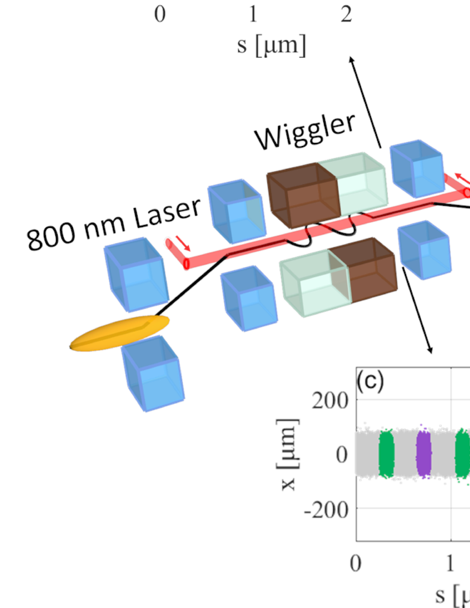
The layout of the proposed scheme is shown in Fig. 1. A periodic energy modulation of the electron beam is induced through interaction with an external laser in a wiggler. The modulator is positioned between a chicane consisting of two doglegs with opposite polarities. The dogleg following the modulator converts the energy modulation into temporal-transverse modulation, while the preceding dogleg ensures the electron beam remains on axis and reduces undesirable effects. The evolution of the phase space is described in detail through matrix calculations. Figure 1(a) shows an example longitudinal phase space. The low-energy electrons and the high-energy electrons are respectively purple and green. The gray part represents electrons with large energy chirp, where the FEL gain is suppressed [8]. Figure 1(c) shows the original transverse distribution of the electron beam. Figure 1(b) and Fig. 1(d) show the energy distribution and the transverse distribution at the entrance of the first section. These subfigures are depicted from simulaiton using typical parameters of Shenzhen Superconducting Soft X-Ray Free-electron Laser (S3FEL) [38] as listed in Table 1. The electron beam extracted from a linear accelerator was characterized by the following parameters: an energy of 2.53 GeV, a flat current of 3 kA, rms normalized emittance of 0.4 mm mrad, and an uncorrelated energy spread of 180 keV. An external laser with a wavelength of 800 nm, a peak power of 50 GW, a waist size of 0.5 mm and a RMS pulse duration of 100 fs is employed, which is currently available with state-of-the-art laser technology [39, 40]. The electron beam interacts with the external laser in a wiggler and obtains an energy modulation amplitude of 10 MeV. The total length the of the wiggler is 0.9 m of 6 periods. The wavelength of the first color and the second color are chosen to be 2 nm and 3 nm. In the simulation of Fig. 1, the dispersion and the momentum compression factor of each dogleg is respectively 30 mm and 90 m to briefly show the principles.
| Parameter | Value |
|---|---|
| Electron beam | |
| Initial energy | 2.53 GeV |
| Initial current | 3 kA |
| Emittance | 0.4 mm mrad |
| Uncorrelated energy spread | 180 keV |
| Longitudinal length | 2.4 m |
| External laser | |
| Wavelength | 800 nm |
| Peak power | 40 GW |
| RMS duration | 100 fs |
| Wiggler | |
| Period | 15 cm |
| Period number | 6 |
| 41.89 | |
| Undulator sections | |
| Period | 3 cm |
| Period number per module | 20 |
| FODO length | 2 m |
| / | 2.118/2.807 |
| FEL wavelength in section 1/2 | 2/3 nm |
| Delay in section 1/2 | 760/740 nm |
The undulators are divided into two sections, each satisfying the conditions for mode locking. Specifically, the sum of the slippage in a single undulator module and the slippage in the following chicane magnet is the wavelength of the external laser. In the first undulator section, low-energy electrons travel off-axis along the undulator and remain fresh slices, while high-energy electrons travel on-axis, generating the first-color mode-locked FEL. In the second undulator section, the low-energy electrons are redirected onto axis to lase the second-color mode-locked FEL. Between the two sections, quadrupoles with transverse offsets are employed as kickers to control the electron bunch orbit. The mode-locked FELs generated in the two undulator sections operate independently, and the time delay between the two colors can be adjusted via a magnetic chicane located near the kickers.
In order to make a linear optics analysis of the proposed scheme, we adopt the beam transport matrix notation of a 6 × 6 matrix for the beam vector defined by , where , and are respectively the horizontal, vertical and longitudinal coordinates, dd and dd are respectively the horizontal and vertical divergences and is the relative energy deviation with respect to the reference particle [41]. The transverse structure can be imprinted into either the horizontal direction or the vertical direction. The primary difference is that the magnetic field in direction decreases much faster than in direction in a planner undulator. For manipulation in direction, the central of the wiggler and the undulators are on the same horizontal plane, so this adjustment can be easily adopted to exiting seeded FELs. Here we leave out for simplicity, i.e., is used in the following and assuming Gaussian distributions for and . The electron beam is first sent through a dogleg whose transport matrix is
| (1) |
where is the length of the first dogleg, and are respectively, the dispersion and the momentum compaction generated in the first dogleg. After that, the electron interacts with the seed laser with the wavelength of in the modulator and gets an energy change sin(). Considering electrons in one seed wavelength range, only the electrons near the largest energy modulation positions lase in the undulator sections. Comparing these electrons with the reference electrons with no energy modulation, we assume the energy modulation could be still linear and the energy chirp to be
| (2) |
So the energy change of these electrons can be written as . Then the corresponding transport matrix for the modulation part of electron beam can be derived as
| (3) |
where is the length of the modulaor and is the momentum compaction generated in the undulator. The momentum compaction of the modulator is usually much smaller than that of the following dispersion section, so is ignored in the following calculation. After the modulator, the energy modulation is converted into temporal-transverse modulation by the downstream dogleg with transport matrix of
| (4) |
where is the length of the downstream dogleg, and are respectively, the dispersion and the momentum compaction generated in the downstream dogleg. The transport matrix for the whole beam line before the undulator is:
| (5) |
where . In a chicane the two doglegs are of the opposite polarities, so we have and . Considering the structure of actual device, the relation between and can be expressed by and , where and is the value of the bending angle of the dipoles in each dogleg. The whole transport matrix after simplification can be expressed by:
| (6) |
Subsequently, the transverse position of the electron after the downstream dogleg can be written as
| (7) |
The term indicates that the transverse modulation is closely associated with the longitudinal energy modulation. The term , and respectively represents the Gaussian background noise from , and . To ensure sufficiently transverse separation of the high-energy electrons and the low-energy electrons, it is expected that . Besides, a properly optimized can enhance the current of the lasing part. For practical parameters, and are limited by the beam emittance, while and are limited by and of the dogleg.
Besides, in the absence of the upstream dogleg, it can be derived from equation (5) that the transverse position of the electron after the downstream dogleg can be written as
| (8) |
The comparison between equation (7) and equation (8) shows that since we usually have , the upstream dogleg avoids the introduction of much larger background noise in the modulation.
III Simulations
Theoretical linear calculations gives a rough estimation of the optimized condition. Three-dimensional numerical simulations are necessary to show the possible performance of the proposed scheme. In the following simulations, the same parameters as in Table 1 are used. Besides, the initial and are 60 m and 1.3 rad. The length of the each dogleg is 5 m and the deflection angle at every dipole is 6 mrad. The electron beam is tracked through the modulator and the doglegs using the code ELEGANT [42] with second-order transport effects taken into account. The FEL lasing processes were simulated using the time-depended mode of GENESIS [43]. These simulations considered realistic transfer matrixes of the elements in the proposed scheme. Various nonlinear effects such as coherent synchrotron radiation, incoherent synchrotron radiation, and longitudinal space charge effects are also included in these simulations.
III.1 Temporal-transverse modulation
The phase space at the end of the wiggler is the same as in Fig. 1(a) and Fig. 1(c). With the modulation amplitude of 10 MeV, is unnecessary to be very large. Here 0.03 m, and the separation of the high energy electrons to the reference particle can be calculated to be 120 m, indicating the seperation of the high-energy and low-energy electrons to be about 240 m.
Figure 2 shows the phase space of the electron beam at the entrance of the undulator. For brevity, 3 cycles are depicted and the length of each cycle is 800 nm. As is shown in Fig. 2(a), the sinusoidal energy modulation is over-compressed, and the highest density is located in the highest- and the lowest-energy extent of the beam. In Fig.2 (b), after the downstream dogleg the central of the highest-energy electrons and the lowest-energy electrons are separated by 200 m, which is large enough for adopting the two-stage fresh-slice lasing [37]. The length of the on-axis extent in a single cycle is about 150 nm in the undulator sections. Figure 2(c) shows that the peak current is enhanced to 5 kA, and the peak current of the on-axis beam is about 4.2 kA. The control of the beam orbit and the FEL performances will be shown in the following section.
III.2 Orbit control along the undulators
In the first stage of 16 undulator modules, the resonant wavelength is 2 nm. The slippage in a single undulator is 40 nm. The slippage induced by a single chicane after an undulator is 760 nm. In the second undulator section of 22 undulator modules, the resonant wavelength is 3 nm. The slippage in the undulator is 60 nm. The slippage induced by the chicane is 740 nm. An adjustable chicane is inserted between the two section to control the interval of the two pulses, which is initially set to be 0 in the following simulation. Two quadrupoles with transverse offset are utilized as kickers to switch the orbit of the bunch. Here the deflection angles of the two kickers are 43.1 rad and 65.0 rad, and the distance between them is 1 m. In the second undulator section, more modules are applied to ensure the FEL saturation for two reasons. On the one hand, the oscillation amplitude of the on-axis orbit is slightly larger than in the first undulator section. On the other hand, the mismatch of the weak focusing of the different undulator also slightly disturbs the FEL gain process.
The orbit of the bunch along the undulator sections are shown in Fig. 3. The purple line represents the transverse properties of the low-energy electrons, and the green line represents the high-energy electrons. In the first undulator section, the amplitude of oscillation of the low-energy electrons is approximately 2 m, and can be considered to be on-axis. The amplitude of oscillation of the high-energy electrons is about 100 m, which is much larger than the beam size and FEL spot size and can be considered to be off-axis. After the two kickers, the amplitude of oscillation of the high energy electrons is 3 m, and the amplitude of oscillation of the high energy electrons is about 100 m.
III.3 Performance of the proposed scheme
It has been demonstrated that the evolution of the radiation field in an undulator in the absence of the high-gain FEL interaction may be approximated by the following wave equation [17, 18]:
| (9) |
where the scaled units introduced in [44] are used: is the scaled electric field, is the interaction length along the undulator in units of the one-dimensional gain length , is the local electron bunch coordinate in units of the cooperation length, is a small initial electron bunching source term assumed constant with respect to . For a series of undulator and chicane modules, the solution was given by [17, 18]:
| (10) |
Here is the slippage in one undulator module in units of , is the scaled interaction length. Assuming the slippage due to the chicane in one module is , the total slippage can be expressed by . And the slippage enhancement factor can be defined to be . The intensity of the spectrum as a function of can be expressed by:
| (11) |
Equation (11) indicates a comb structure in the spectrum, with the amount of the modes of about , and the scaled mode spacing of . The total spectrum bandwidth can be calculated by . Here is the period number in a single undulator. In actual simulations, the high-gain FEL interaction and associated bandwidth narrowing as the interaction progresses may reduce the total spectrum bandwidth to about 50% [18].
Taking the peak current to be 4200 A and other parameters given in Table I, the interval of the photon of each mode can be calculated to be = 1.553 eV in both the undulator sections. Ignoring the influence of the complex transverse distribution at the current peak, the pierce parameter is estimated to be and the gain length is = 0.661 m in the first undulator section. Assuming , the coherence time is calculated to be 147 as. In the second undulator section, the pierce parameter is estimated to be . The gain length and the coherence time are respectively calculated to be = 0.471 m and 157 as.
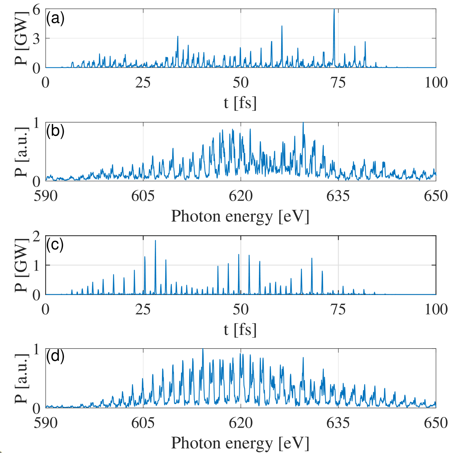
The simulation results of a single shot are illustrated in Fig. 4 when the time delay between the two undulator sections is set to 0. In the first undulator section, the performances of the FEL at the end of 13 undulators are shown in Fig. 5(a) and Fig. 5(b). Figure. 5(a) give a train of pulses evenly spaced by 1.33 fs, with the entire pulse energy of 4.23 J, the average peak power of 0.517 GW and the average pulse duration of 248 as. Due to the slippage induced by the delay chicanes, the total amount of the pulses is slightly more than the amount of the electron cycles. It is also the reason that the peak power of the pulses near the bunch tail is lower than the average value. Besides, the peak power of the FEL from the off-axis beam is suppressed to be lower than 0.01 GW. In Fig. 5(b), the spectral width (FWHM) is 2.10%, consisting of 40 modes evenly spaced by 0.25% (1.55 eV). The average bandwidth of each individual mode is 0.41 eV. The spectrum is consistent with theoretical calculations.
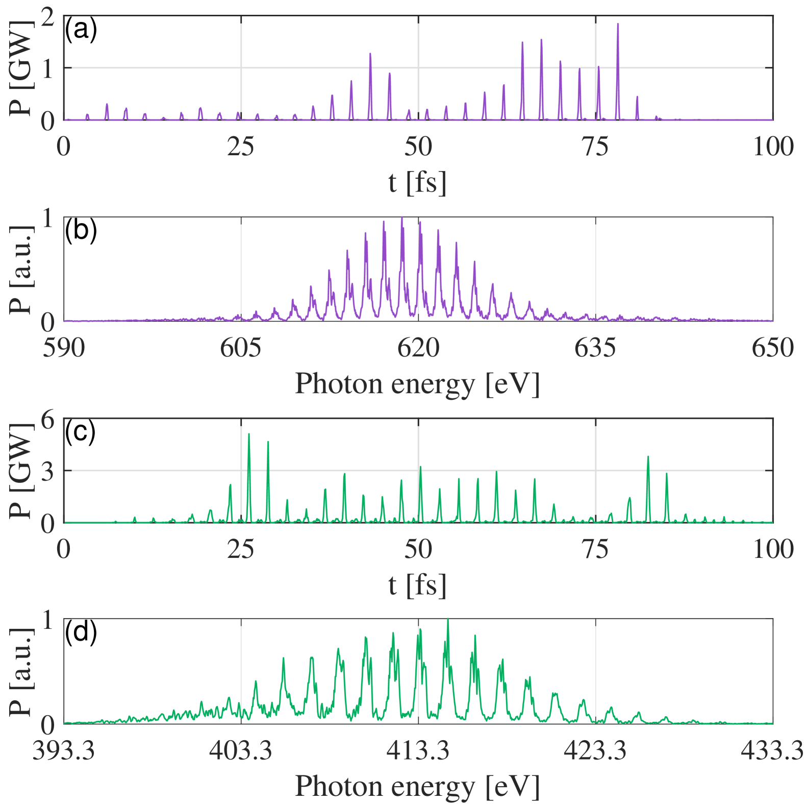
In the second stage, the performances of the FEL at the end of 19 undulators are shown in Fig. 5(c) and Fig. 5(d). Figure 5(c) give a train of pulses evenly spaced by 1.33 fs, with the entire pulse energy of 19.4 J, the average peak power of 1.63 GW and the average pulse duration of 320 as. The average power of the FEL pulses from off-axis reaches about 0.15 GW due to a longer distance of the undulators. Meanwhile, as is shown in Fig. 5(d), the background noise in the spectrum is also slightly worse. Specifically, the spectral width (FWHM) is 3.17%, consisting of 26 modes evenly spaced by 0.50% (1.55 eV), and the average bandwidth of each individual mode is 0.45 eV.
Comparing the simulation results with the calculation, it can be found that the spectrum of the FEL is well consistent with the theoretical calculation, which demonstrates that mode-locking occurs in both undulator sections. Besides, since the complex transverse distribution near the current peak slightly disturbs the gain process, the average pulse duration is slightly longer than the calculation.
III.4 Influence of the delay chicane
Assuming the time delay of the chicane to be , the induced momentum compaction of the delay chicane can be written as . From the end of the wiggler to the entrance of the second undulator section, the total momentum compaction can be written as , where is the momentum compaction induced in the undulator section 1. For the undulator section 1 with modules, . At the end of the first undulator section, since the bunch is over compressed, the current will gradually decrease with increasing. When , the delay chicane have little influence on the phase space of the beam. Here m, and m. The corresponding delay of is 321 fs. Different from the ESASE mode-locking scheme [18] in which case the peak current is enhance to several times of the initial current, in the proposed scheme the current is only slightly enhanced near the electrons with maximum modulation. So the feasible ranges of both and are supposed to be larger.
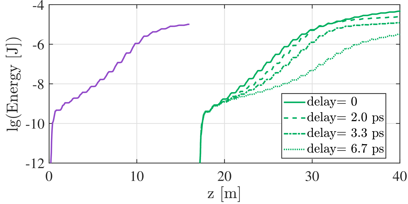
To briefly show the influence of the delay chicane, we scan the delay and plot the gain curves of the proposed scheme in Fig. 5. In case of no time delay between the two undulator sections, the gain curves of the FEL pulse energy along undulator position in the two undulator sections are depicted as the solid lines. Purple line represents the gain curve in the first undulator section. Green lines represent the gain curve in the second undulator section. Green dotted lines represent the gain curve in the second undulator section with delays of several typical values. At the end of 19 m in the second undulator section (36 m from the beginning of the first undulator section), the pulse energies are respectively 28.84 J, 19.49 J, 9.77 J and 1.35 J when the delay is set to be 0, 2.0 ps, 3.3 ps and 6.7 ps. It can be observed that the FEL gain process is significantly suppressed only when increases to more than 3.3 ps (about for the simulated parameters). When , the FEL gain curve is very close to the case of .
III.5 Comparison with the original scheme
To give a brief contrast of the proposed scheme and the conventional mode-locked FEL, simulation is performed with mostly same parameters. The phase space and the transverse distribution of the modulated electron beam before the undulator is the same as in Fig. 1(a) and Fig. 1(c). The length of the lowest-energy electrons of the beam is about 90 nm. The undulators have the same parameters as in the first undulator section in the proposed scheme. The pierce parameter is calculated to be . At the same location with Fig. 4(a) and Fig. 4(b), Fig. 6 (a) and Fig. 6(b) depict the power profile and the spectrum of the FEL at the end of 13 undulators. An obvious difference is that although only the low-energy electrons are precisely matched with the lattice, the high-energy electrons still lase. Similar phenomena can be found in Ref. [17] and Ref. [18], especially for smaller modulation amplitude. In this situation, the interval between the pulses is half the wavelength of the seed laser, although the slippage of an undulator and a delay chicane remains one wavelength of the seed laser. With larger energy modulation amplitude, the lasing of the high energy part can be slightly suppressed, but remains non-negligible. As is shown in Fig. 6(a), in a single shot the average power and the average pulse duration of all the pulses is 1.22 GW and 474 as. To be specific, the average peak power from the low-energy electrons is 1.72 GW, and the average peak power of the pulses from the high-energy electrons can be as large as 0.72 GW. Since all the electrons are on axis, the average power is larger than in Fig.4 (a). Under this condition, the electrons in the energy chirps also begin to lase, and increase the background noise. In Fig. 6(b), the bandwidth of the whole spectrum is 3.2%. Although the internals of the modes are still 1.55 eV, the spectrum is less similar to a gaussian distribution compared with Fig. 4(b). More random noises appear in both the whole spectrum and a single mode, which is usually observed in a SASE spectrum. Figure 6(c) and Fig. 6(d) show the temporal power profile and the spectrum at another location of 9 m, where the background noise from the chirped electrons is much lower than at 13 m. In Fig. 6(c), the average peak power and the average pulse duration of the all pulses are respectively 0.38 GW and 203 as. The average power of FEL from the low-energy electrons is 0.62 GW, while the average power of FEL from the high-energy electrons is 0.14 GW. The lasing from the high-energy electrons is still far larger than in Fig. 4(a). In Fig. 6(d), the bandwidth of the spectrum is 4.19%, and the bandwidth of a single mode is 0.605 eV. Since the delay after every undulator is still 780 nm but not 380 nm, correlation forms at every two FEL pulses and phase of the adjacent pulses is not correlated. As a result, splitting peaks appear in each mode. These comparisons show that in the proposed scheme FEL from the off-axis electron parts can be more efficiently suppressed, so the mode-locked FEL generated from the proposed scheme performs better in both the power profile and the spectrum than the original scheme.
IV Conclusion
In conclusion, we firstly propose to place the laser modulator within a chicane to generate two-color attosecond mode-locked FEL pairs. Matrix calculations and simulations demonstrate that the periodic energy modulation from external laser can be transformed to the periodic temporal transverse modulation for the two-stage fresh-slice scheme. Simulations demonstrate that the proposed scheme is capable of generating GW-level attosecond x-ray mode-locked FEL with two independent color and tunable temporal separations ranging from 0 to hundreds of femtoseconds. Compared to the conventional mode-locked FEL, the proposed scheme can generate purer and more powerful pulses in each undulator section.
In the calculation and simulation, the transverse modulation is chosen to be in direction in order to be easily applied in the seeded FEL facilities. For the transverse modulation in direction, the demand of the energy modulation depth can be reduced to achieve enough spatial deviation, thereby enabling further reduction of the peak power of the external laser. In addition, it is worth noting that the proposed dogleg-modulator-dogleg structure combined with orbit control can be adopted for other requirements. For example, the proposed scheme with a single undulator section can generate a single-color attosecond mode-locked FEL. The combination with normal undulators can generate two color pulse trains. The combination with few-cycle external lasers has the potential to generate independent femtosecond two color pulses or a cascaded high power isolated attosecond FEL.
Acknowledgements.
The authors would like to thank Xiaozhe Shen (IASF), Yujie Lu (Zhangjiang Laboratory) and Weijie Fan(Zhangjiang Laboratory) for their helpful discussions. This work is supported by the Scientific Instrument Developing Project of Chinese Academy of Sciences (Grant No. GJJSTD20220001) and the National Natural Science Foundation of China (Grant No. 22288201).References
- Hentschel et al. [2001] M. Hentschel, R. Kienberger, C. Spielmann, G. A. Reider, N. Milosevic, T. Brabec, P. Corkum, U. Heinzmann, M. Drescher, and F. Krausz, Attosecond metrology, Nature 414, 509 (2001).
- Kühn et al. [2017] S. Kühn, M. Dumergue, S. Kahaly, S. Mondal, M. Füle, T. Csizmadia, B. Farkas, B. Major, Z. Várallyay, E. Cormier, et al., The eli-alps facility: the next generation of attosecond sources, J. Phys. B 50, 132002 (2017).
- McNeil and Thompson [2010] B. W. McNeil and N. R. Thompson, X-ray free-electron lasers, Nat. Photonics 4, 814 (2010).
- Emma et al. [2010] P. Emma, R. Akre, J. Arthur, R. Bionta, C. Bostedt, J. Bozek, A. Brachmann, P. Bucksbaum, R. Coffee, F.-J. Decker, et al., First lasing and operation of an ångstrom-wavelength free-electron laser, Nat. Photonics 4, 641 (2010).
- Zholents [2005] A. A. Zholents, Method of an enhanced self-amplified spontaneous emission for x-ray free electron lasers, Phys. Rev. ST Accel. Beams 8, 040701 (2005).
- Franz et al. [2024] P. Franz, S. Li, T. Driver, R. R. Robles, D. Cesar, E. Isele, Z. Guo, J. Wang, J. P. Duris, K. Larsen, et al., Terawatt-scale attosecond x-ray pulses from a cascaded superradiant free-electron laser, Nat. Photonics , 1 (2024).
- Yan et al. [2024] J. Yan, W. Qin, Y. Chen, W. Decking, P. Dijkstal, M. Guetg, I. Inoue, N. Kujala, S. Liu, T. Long, et al., Terawatt-attosecond hard x-ray free-electron laser at high repetition rate, Nat. Photonics , 1 (2024).
- Saldin et al. [2006] E. L. Saldin, E. A. Schneidmiller, and M. V. Yurkov, Self-amplified spontaneous emission fel with energy-chirped electron beam and its application for generation of attosecond x-ray pulses, Phys. Rev. ST Accel. Beams 9, 050702 (2006).
- Giannessi et al. [2011] L. Giannessi et al., Self-amplified spontaneous emission free-electron laser with an energy-chirped electron beam and undulator tapering, Phys. Rev. Lett. 106, 144801 (2011).
- Duris et al. [2020] J. Duris, S. Li, T. Driver, E. G. Champenois, J. P. MacArthur, A. A. Lutman, Z. Zhang, P. Rosenberger, J. W. Aldrich, R. Coffee, et al., Tunable isolated attosecond x-ray pulses with gigawatt peak power from a free-electron laser, Nat. Photonics 14, 30 (2020).
- Maroju et al. [2020] P. K. Maroju, C. Grazioli, M. Di Fraia, M. Moioli, D. Ertel, H. Ahmadi, O. Plekan, P. Finetti, E. Allaria, L. Giannessi, et al., Attosecond pulse shaping using a seeded free-electron laser, Nature 578, 386 (2020).
- Sun et al. [2024] H. Sun, X. Wang, L. Zeng, and W. Zhang, Synthesis of microbunching rotation for generating isolated attosecond soft x-ray free-electron laser pulses, Phys. Rev. Res. 6, 043242 (2024).
- Palacios and Mart´ın [2020] A. Palacios and F. Martín, The quantum chemistry of attosecond molecular science, Wires. Comput. Mol. Sci. 10, e1430 (2020).
- Li et al. [2022] S. Li, T. Driver, P. Rosenberger, E. G. Champenois, J. Duris, A. Al-Haddad, V. Averbukh, J. C. Barnard, N. Berrah, C. Bostedt, et al., Attosecond coherent electron motion in auger-meitner decay, Science 375, 285 (2022).
- Zhu and Reis [2024] D. Zhu and D. A. Reis, Attosecond x-ray laser vision, Nat. Photonics 18, 1232 (2024).
- Ilchen et al. [2025] M. Ilchen, E. Allaria, P. Rebernik Ribič, H.-D. Nuhn, A. Lutman, E. Schneidmiller, M. Tischer, M. Yurkov, M. Calvi, E. Prat, et al., Opportunities for gas-phase science at short-wavelength free-electron lasers with undulator-based polarization control, Phys. Rev. Res. 7, 011001 (2025).
- Thompson and McNeil [2008] N. R. Thompson and B. W. J. McNeil, Mode locking in a free-electron laser amplifier, Phys. Rev. Lett. 100, 203901 (2008).
- Kur et al. [2011] E. Kur, D. Dunning, B. McNeil, J. Wurtele, and A. Zholents, A wide bandwidth free-electron laser with mode locking using current modulation, New J. Phys. 13, 063012 (2011).
- Dunning et al. [2013] D. J. Dunning, B. W. J. McNeil, and N. R. Thompson, Few-cycle pulse generation in an x-ray free-electron laser, Phys. Rev. Lett. 110, 104801 (2013).
- Paul et al. [2001] P.-M. Paul, E. S. Toma, P. Breger, G. Mullot, F. Augé, P. Balcou, H. G. Muller, and P. Agostini, Observation of a train of attosecond pulses from high harmonic generation, Science 292, 1689 (2001).
- Duris et al. [2021] J. P. Duris, J. P. MacArthur, J. M. Glownia, S. Li, S. Vetter, A. Miahnahri, R. Coffee, P. Hering, A. Fry, M. E. Welch, et al., Controllable x-ray pulse trains from enhanced self-amplified spontaneous emission, Phys. Rev. Lett. 126, 104802 (2021).
- Prat et al. [2023] E. Prat, A. Al Haddad, C. Arrell, S. Augustin, M. Boll, C. Bostedt, M. Calvi, A. L. Cavalieri, P. Craievich, A. Dax, et al., An x-ray free-electron laser with a highly configurable undulator and integrated chicanes for tailored pulse properties, Nat. Commun. 14, 5069 (2023).
- Prat et al. [2024] E. Prat, W. Hu, C. Arrell, M. Calvi, P. Dijkstal, R. Follath, and S. Reiche, Experimental demonstration of mode-coupled and high-brightness self-amplified spontaneous emission in an x-ray free-electron laser, Phys. Rev. Lett. 133, 205001 (2024).
- Diddams et al. [2020] S. A. Diddams, K. Vahala, and T. Udem, Optical frequency combs: Coherently uniting the electromagnetic spectrum, Science 369, eaay3676 (2020).
- Zhao et al. [2020] K. Zhao, Y. Li, X. Xiao, and C. Yang, Nonlinear multimode interference-based dual-color mode-locked fiber laser, Opt. Lett. 45, 1655 (2020).
- Han et al. [2020] Y. Han, Y. Guo, B. Gao, C. Ma, R. Zhang, and H. Zhang, Generation, optimization, and application of ultrashort femtosecond pulse in mode-locked fiber lasers, Prog. Quant. Electron. 71, 100264 (2020).
- Guo et al. [2024] Z. Guo, T. Driver, S. Beauvarlet, D. Cesar, J. Duris, P. L. Franz, O. Alexander, D. Bohler, C. Bostedt, V. Averbukh, et al., Experimental demonstration of attosecond pump-probe spectroscopy with an x-ray free-electron laser, Nat. Photonics , 1 (2024).
- Lutman et al. [2014] A. Lutman, F.-J. Decker, J. Arthur, M. Chollet, Y. Feng, J. Hastings, Z. Huang, H. Lemke, H.-D. Nuhn, A. Marinelli, et al., Demonstration of single-crystal self-seeded two-color x-ray free-electron lasers, Phys. Rev. Lett. 113, 254801 (2014).
- Marinelli et al. [2015] A. Marinelli, D. Ratner, A. Lutman, J. Turner, J. Welch, F.-J. Decker, H. Loos, C. Behrens, S. Gilevich, A. Miahnahri, et al., High-intensity double-pulse x-ray free-electron laser, Nat. Commun. 6, 6369 (2015).
- Malyzhenkov et al. [2020] A. Malyzhenkov, Y. P. Arbelo, P. Craievich, P. Dijkstal, E. Ferrari, S. Reiche, T. Schietinger, P. Juranić, and E. Prat, Single-and two-color attosecond hard x-ray free-electron laser pulses with nonlinear compression, Phys. Rev. Res. 2, 042018 (2020).
- De Ninno et al. [2013] G. De Ninno, B. Mahieu, E. Allaria, L. Giannessi, and S. Spampinati, Chirped seeded free-electron lasers: Self-standing light sources for two-color pump-probe experiments, Phys. Rev. Lett. 110, 064801 (2013).
- Ferrari et al. [2016] E. Ferrari, C. Spezzani, F. Fortuna, R. Delaunay, F. Vidal, I. Nikolov, P. Cinquegrana, B. Diviacco, D. Gauthier, G. Penco, et al., Widely tunable two-colour seeded free-electron laser source for resonant-pump resonant-probe magnetic scattering, Nat. Commun. 7, 10343 (2016).
- Prince et al. [2016] K. Prince, E. Allaria, C. Callegari, R. Cucini, G. De Ninno, S. Di Mitri, B. Diviacco, E. Ferrari, P. Finetti, D. Gauthier, et al., Coherent control with a short-wavelength free-electron laser, Nat. Photonics 10, 176 (2016).
- Prat et al. [2022] E. Prat, P. Dijkstal, E. Ferrari, R. Ganter, P. Juranić, A. Malyzhenkov, S. Reiche, T. Schietinger, G. Wang, A. A. Haddad, et al., Widely tunable two-color x-ray free-electron laser pulses, Phys. Rev. Res. 4, L022025 (2022).
- Wang et al. [2024] G. Wang, P. Dijkstal, S. Reiche, K. Schnorr, and E. Prat, Millijoule femtosecond x-ray pulses from an efficient fresh-slice multistage free-electron laser, Phys. Rev. Let. 132, 035002 (2024).
- Lutman et al. [2016] A. A. Lutman, T. J. Maxwell, J. P. MacArthur, M. W. Guetg, N. Berrah, R. N. Coffee, Y. Ding, Z. Huang, A. Marinelli, S. Moeller, et al., Fresh-slice multicolour x-ray free-electron lasers, Nat. Photonics 10, 745 (2016).
- Guetg et al. [2018] M. W. Guetg, A. A. Lutman, Y. Ding, T. J. Maxwell, and Z. Huang, Dispersion-based fresh-slice scheme for free-electron lasers, Phys. Rev. Lett. 120, 264802 (2018).
- Wang et al. [2023] X. Wang, L. Zeng, J. Shao, Y. Liang, H. Yi, Y. Yu, J. Sun, X. Li, C. Feng, Z. Wang, et al., Physical design for shenzhen superconducting soft x-ray free-electron laser (s3fel), Proc. of IPAC’23, Venice, Italy , TUPL043 (2023).
- Petrov et al. [2007] V. Petrov, F. Noack, P. Tzankov, M. Ghotbi, M. Ebrahim-Zadeh, I. Nikolov, and I. Buchvarov, High-power femtosecond optical parametric amplification at 1 khz in bib 3 o 6 pumped at 800 nm, Opt. Express 15, 556 (2007).
- Tsai et al. [2022] M.-S. Tsai, A.-Y. Liang, C.-L. Tsai, P.-W. Lai, M.-W. Lin, and M.-C. Chen, Nonlinear compression toward high-energy single-cycle pulses by cascaded focus and compression, Sci. Adv. 8, eabo1945 (2022).
- Chao et al. [2013] A. W. Chao, M. Tigner, H. Weise, and F. Zimmermann, Handbook of accelerator physics and engineering (World scientific, 2013).
- Borland [2000] M. Borland, Elegant: A flexible sdds-compliant code for accelerator simulation, Argonne National Lab. Tech. , Report No. LS287 (2000).
- Reiche [1999] S. Reiche, Genesis 1.3: a fully 3d time-dependent fel simulation code, Nucl. Instrum. Methods Phys. Res., Sect. A 429, 243 (1999).
- Bonifacio et al. [1989] R. Bonifacio, B. McNeil, and P. Pierini, Superradiance in the high-gain free-electron laser, Phys. Rev. A 40, 4467 (1989).