Josephson vortices and persistent current in a double-ring supersolid system
Abstract
We theoretically investigate the properties of ultra-cold dipolar atoms in radially coupled, concentric annular traps created by a potential barrier. The non-rotating ground-state phases are investigated across the superfluid-supersolid phase transition, revealing a particle imbalance between the two rings and a preferential density modulation in the outer ring. Near the phase transition on the superfluid side, applying rotation can induce density modulations in either ring, depending on the angular momentum and barrier strength. For low angular momentum, such rotation-induced density modulation forms in the outer ring, while for high angular momentum and weak barriers, it emerges in the inner ring. Rotation can lead to persistent currents and the nucleation of a vortex residing either at the center (central vortex) or at the ring junction (Josephson vortex). Josephson vortices can also form at the junctions of the localized density sites induced by rotation in the inner ring, a behavior that is unique to our system. By switching off the trap and allowing the system to expand, distinct interference patterns emerge, which can be analyzed to identify and distinguish between various vortex configurations, and thus can be observed in current state-of-the-art experiments.
I Introduction
Superfluidity is well-known to be closely related to the phenomenon of Bose-Einstein condensation (BEC) [1, 2, 3] and manifests through the existence of vortices and persistent currents (see the review [4]). In analogy to superconducting rings [5, 6], multiply-connected atomic condensates in toroidal traps may exhibit metastable flow [7, 8, 9, 10, 11, 12, 13, 14, 15] (see also the recent review [16]). Likewise, the Josephson effect (originally discovered in superconducting systems [17]) may govern the tunneling between purely superfluid (SF) states that are weakly linked by a junction formed by an external potential. For singly-connected systems, the atomic analogue of the Josephson effect has been intensively studied, see, e.g., Refs. [18, 19, 20, 21, 22, 23, 24, 25, 26, 27]. Particularly interesting however is the combination of the Josephson effect and persistent flow that can be achieved by trapping a BEC in a double (or multiple) ring geometry, arranged coaxially or coplanarly [28, 29, 30, 31, 32, 33, 34, 35, 36, 37, 38, 39]. The coupling between the rings across an azimuthally symmetric barrier may then lead to an intriguing interplay between Josephson tunneling and persistent currents (PCs) in the system. A distinctive feature of such multi-ring potentials is their ability to support either identical or distinctly quantized flows across the junctions, with some or all of the rings carrying quantized angular momentum. The phase difference between the rings leads to the formation of vortices at the Josephson barriers, commonly referred to as Josephson vortices (JVs). They have been observed in superconductors [40] and polariton superfluids [41], and are also well studied in BECs of alkali atoms [42, 29, 43, 25, 44, 37, 38, 45].
Dipolar BECs (as reviewed in [46, 47, 48, 49]) add another interesting twist to the physics of JVs and PCs, due to the long-ranged interaction. After first experiments with Chromium [50, 51], also lanthanides with larger magnetic dipole moments [52, 53, 54, 55] became of interest, where similarly to a classical Rosensweig transition, regular arrays of droplets may form [56, 57]. Under certain conditions, these droplets may phase-coherently overlap and a periodic solid-like structure may emerge while the coherent superfluid properties are partly maintained [58, 59, 60, 61]. Such “supersolid” (SS) state of matter was predicted early on [1, *Gross1958, *Yang1962, *Chester1970, *Leggett1970] for helium but remained elusive [66]. Unequivocal evidence for its existence however only came more recently from the above experiments with ultra-cold dysprosium [59, 60, 58, 61] and erbium [60]. Subsequent studies analyzed the excitation spectra [67, *Natale2019, *Hertkorn2019, *Schmidt2021, *Hertkorn2021supersolidity2D, *Hertkorn2021densityfluctuations, 73, *poli_2d_excitation_2024] associated with the SF-SS transition and provided deeper insights into various dynamical phenomena [75, *Ilzhofer2021, *Sohmen2021, *Bland2022_2Dsupersolid, *alana_roton_SS_2023, *Mukherjee_linear_chain, *Mistakidis_tunneling_2024]. Vortices as indicators of superfluidity in the SS state were also studied [82, 83, 84, 85, 86]. Interestingly, already long before the realization of SSs, it was suggested that a SF of dipolar atoms polarized perpendicular to the symmetry axis of a toroidal trap will form a self-induced Josephson junction, splitting the SF in two halves on either side of the ring [87]. More recently, the SS state has been interpreted as an array of such junctions [88, 89, 90, 91], albeit here as a consequence of the SS density modulation. A connection could be drawn between the superfluid fraction as a measure of the density modulation in the SS, and the Josephson effect [88]. For a dipolar SS in a toroidal trap, earlier studied in [92, 93, 94] and yet to be realized experimentally, the absence of inhomogeneities typical of cigar-shaped traps leads to a collective excitation spectrum where first sound, second sound, and Higgs modes can decouple [95]. When persistent current exists, the angular momentum per particle (in the SS being less than unity in units of ) is determined by the superfluid fraction [92, 93, 94].
In this work, motivated by the advantages of the toroidal confinement and the existence of novel phases in dipolar BECs, we investigate dipolar BECs confined in coplanar double rings sharing a common center (as displayed by the density iso-surfaces in Fig. 1 on the next page). Pertinent questions are how the spontaneous density modulation of the SS state evolves in a double-ring as the relative dipolar interaction strength increases, how the persistent current develops, and how topological defects emerge in the presence of rotation.
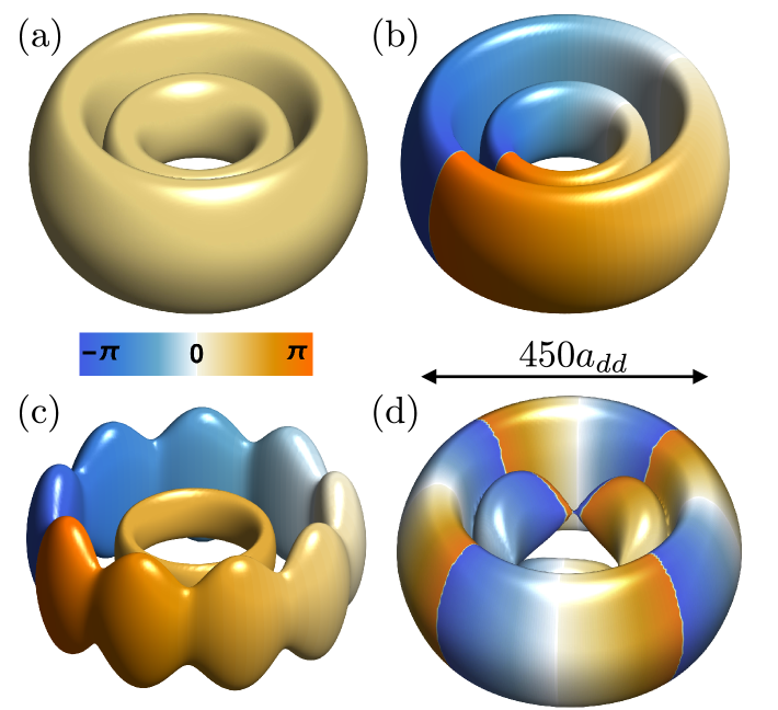
The system remains in a pure SF state when both rings exhibit azimuthally uniform density profiles, as shown in Figs. 1(a)-(b). If a density modulation occurs in one or both rings, The system may also form a SS state [Figs. 1(c)-(d)], with a density modulation in one or both of the rings. We note that such a SS system contains two types of junctions: (1) one between the rings, produced artificially by the azimuthally symmetric barrier between the rings, and (2) those formed by the atoms that take part in the superfluid flow of the SS.
The long-range dipolar interaction creates a population difference between the rings, and the supersolid density modulation preferentially appears in the outer ring. Near the SF-SS phase transition, a system that initially is in a SF state can form a density modulation when forced to acquire angular momentum through rotation. This may happen either in the outer or inner ring, depending on the system’s angular momentum and the barrier strength. For relatively small angular momentum, it is the outer ring that contributes to the formation of the SS, regardless of the barrier strength. For large angular momentum, if the barrier is weak, rotation can facilitate formation of a SS in the inner ring.
When a critical rotation frequency is exceeded, topological defects such as vortices are nucleated as a consequence of the superfluid properties of the system, and also persistent currents may occur. A non-zero density along the azimuthal barrier, i.e. in between the two rings, significantly affects the pathway of vortex nucleation. We in the following refer to vortices that are located at the junction barrier between the rings as [Fig. 1(c)]. In this case, metastable persistent current exits only in the outer ring, as we observe only for the isolated rings. The entire system can exhibit a persistent current when a vortex is located at the center, referred to as a central vortex (CV), which occurs when a density bridge exists between the rings due to a weaker barrier [Fig. 1(b)]. In this latter configuration, sufficiently high rotation can induce formation periodic density modulation in the inner ring, with vortices located at the junctions between the density sites [Fig. 1(d)]. These JVs are unique to the double-ring dipolar system, where the system’s tendency to form spontaneous density modulation makes their existence possible. We refer to them as . Notably, these structures can be observed in experiments through the interference of different parts of the condensate, producing distinct patterns when the trap is switched off.
The remainder of this paper is organized as follows: We introduce our setup and theoretical framework in Sec. II. Our results are discussed in Sec. III. Specifically, we first examine the static ground-state structures that develop in the double-ring system in Sec. III.1. The rotational dynamics of the system are then analyzed in Sec. III.2 under two distinct configurations: one where the rings remain separated [Sec. III.2.1] and another where they are connected [Sec. III.2.2]. A phase diagram explaining the existence of JVs and CVs is presented in Sec. III.2.3. We discuss how interferometric techniques can be used to distinguish between these states in Sec. III.3. After conclusive remarks and an outlook in Sec. IV, Appendix A provides some additional details of the numerical simulations performed in this work.
II Model and methods
The confinement setup can be realized using a toroidal potential of radius , supplemented by a Gaussian potential centered at forming an azimuthally symmetric barrier that makes it possible to split the confinement into an inner and an outer ring:
| (1) |
The potential has two minima located at , and . The confinement frequency in the radial plane is given by , while that along is . The width and strength of the barriers are characterized by the parameters and , respectively. In the following, we analyze the rotational properties of dysprosium atoms confined by the above potential, in a co-rotating reference frame. The behavior can be modeled using the usual extended Gross-Pitaevskii equation (eGPE) with the energy functional
| (2) |
Here and represent the trap rotation frequency and angular momentum operator, respectively. The contact interaction has strength and can be tuned by varying the s-wave scattering length . We denote the particle mass by . The angle is defined as the angle between the position vector and the dipole moment, which is assumed to align with the -direction. The coefficient of the dipole-dipole interaction (DDI) is , where represents the dipolar length. The last term in Eq. (II) is the so-called Lee-Huang-Yang (LHY) correction where and [96, 97]. The ground states are determined by solving eGPE equation using the split-step Fourier method in imaginary time, while real-time evolution is employed to explore the system’s dynamical behavior. We here consider 164Dy atoms with . The trapping frequencies are and the width .
By varing , and , in the following we systematically explore both the non-rotational and rotational properties of the system. When exceeds a critical value, JVs and CVs can emerge in the ground state, identified by examining the lowest energy as function of angular momentuma, (i.e., the so-called yrast line [98]). The energy for a single component in a toroidal setup can be expressed as the sum of a term quadratic in , arising from the kinetic energy, and another function primarily originating from particle interactions, which is symmetric and periodic in when central vortices are generated in the system [2]. A minimum in energy at a value indicates a metastable persistent current with angular momentum in the ground state [2, 99, 100, 101].
III Results and Discussions
III.1 Non-rotating ground states
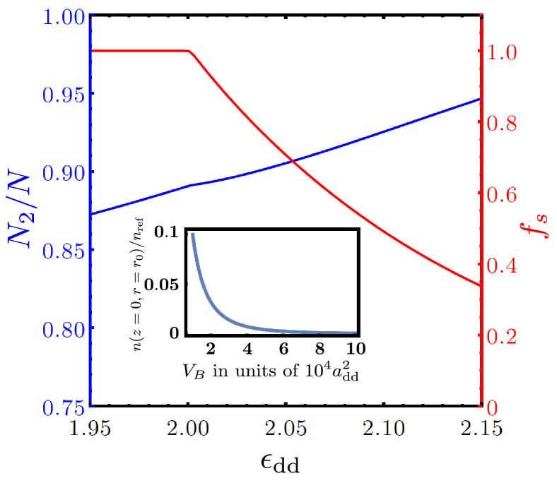
Let us first highlight the static ground state properties of the double-ring system, initially focusing on barrier strength , which separates the rings without any density overlap between them. The density configurations are determined by how the dipolar atoms are distributed within the two rings. The particle number of the outer rings, , is shown as a function of in Fig. 2(a). It indicates that the outer ring always has a higher population [see also Fig. 1] increasing further as the dipolar interaction becomes stronger. This behavior can be understood by considering both the long-range nature of interactions between the atoms and the underlying confining potential. The dipolar atoms experience repulsion in the x-y plane and attraction along the polarization axis. To minimize repulsion and, consequently, the total energy, it is energetically favorable for the atoms to occupy the ring with a larger radius. However, placing all the atoms there would enhance both the potential energy and the total energy of the system. Consequently, the density in the inner ring remains non-zero. The smaller the value of , the more particles it contains.
The imbalance of population also determines if (and how) the density modulation emerges. For smaller , the system is expectedly in the SF regime. A representative 3D density isosurface of such state at is shown in Fig. 1(a). (Note that here, the phase is constant). Earlier studies in a simply-connected confinement potential have demonstrated that at a fixed interaction strength, for increasing particle number the formation of the SS state is favored [58, 59, 60]. Owing to its larger population, the condensate in the outer ring becomes more prone to a periodic density modulation (similar to the one in Fig. 1(c), but with uniform phase) as increases. For a quantitative analysis of the phase transition, we calculate the superfluid fraction, , where [65, 102]. The classical moment of inertia is obtained from the ground state. The as a function of is shown in Fig. for the parameters specified above. For , we have , as expected for the SF. For larger values of , the ground state is a SS, with the outer ring showing nine density maxima for dipolar strength in the interval . We note that considering larger , and decreasing , the density modulation may occur in both rings. However, we restrict our analysis to the scenario of density modulation forming only in the outer ring. We also note that for atoms with only short-range interactions it is possible to have almost equal number of atoms in both rings [38], but intrinsic density modulations forming a SS do not develop in these systems.
Examining the role of the Gaussian barrier, we find that, within the range , its impact on the superfluid fraction and the corresponding phase transition is weak.
Specifically,
for , the eight-fold modulated state becomes energetically favorable for . A smaller value of leads to a density overlap between the rings along the radial direction; see the inset of Fig. 2 where we have shown the density at the position of barrier for varying barrier strength . As we will discuss in the subsequent section, when the system is set into rotation, such finite density at the azimuthal barrier significantly influences the vortex position and thus the angular momentum of system.
III.2 Rotational ground states:
Let us now investigate the rotational properties of the system to understand how the inter-ring connection determines which part of the system acquires angular momentum and how it influences the nucleation of topological defects.
III.2.1 Separated rings
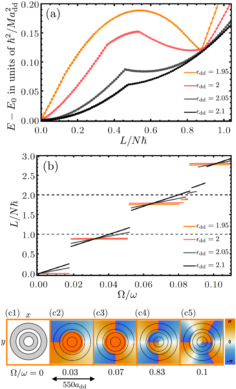
We first discuss the case in which the rings are completely separated by a barrier of strength . By analyzing the energy as a function of angular momentum [Fig. 3(a)], the angular momentum as a function of rotation frequency [Fig. 3(b)], and the spatial phase distributions [Figs. 3(c1)–(c5)], we can effectively characterize the existence of persistent currents in the ground state, and the vortex nucleation. For the SF state at , the yrast line exhibits the characteristic downward cusp, i.e., a V-shaped minimum, at , identifying the state that can host a persistent current [orange line in Fig. 3(a)]. This is further validated by calculating the ground state in the rotating frame, and analyzing the vs. behavior, which exhibits a sudden jump in angular momentum to at the critical rotation frequency , as shown in [Fig. 3(b)]. Notably, this value matches with the fraction of particles in the outer ring , indicating that angular momentum is carried by it. This becomes evident from Fig. 3(c2), where a representative two-dimensional phase profile at , reveals a uniform phase in the inner ring, while the outer ring exhibits a full winding. This suggests that a vortex resides at the junction between the rings. It is indetified as a in the rotating ground state. In the SF state, the wave function of a located at position can be expressed as
| (5) |
Here, the term represents the angle between and the reference vector . This expression is only valid when the density at vanishes to ensure the continuity of the wave function. The phase of the inner ring is inherently linked to the position of the . Specifically, at the location of the the phase of the wave function has a jump of in the radial direction.
Energy minima in the yrast line [only one is shown here for brevity] correspond to a metastable state where persistent current can be created within a specific ranges of rotation frequencies. For instance, the next state, appearing for , has , and accommodates two s. A particularly intriguing transition occurs at , when one migrates to the center, giving rise to a state that hosts both a and a CV. In this configuration, each particle in the inner ring acquires superfluid circulation, leading to . Similarly, by further increasing the , it is possible to create a system that supports multiples and CVs [see Fig. 3(c5) for two s and one CV].
In the SS state (), the minimum of the yrast line shifts to a lower value of . For smaller angular momentum the variation of energy is more parabolic in nature for larger in contrast to the linear variation that we observe in SF. Moreover, a kink appears at due to the intersection of two energy branches arising from the system’s kinetic energy. Notably, while in a single-ring SS, the kink location at remains unchanged and is determined solely by the total number of particles, in a double-ring system it shifts towards as the outer ring progressively becomes more populated for larger ; see and in Fig. 3(a). The energy barrier that prevents the metastable state from decaying into the non-rotating state also depends on ; compare the range between and . Additionally, in the angular momentum of the ground states, we observe a gradual slope linked to the value of before it abruptly jumps to a higher value with increasing rotation frequency. While the rotational states for different exhibit the same number of and CVs, their critical rotation frequencies differ due to a varying population in the outer ring. If the superfluid fraction drops below a critical threshold, vortices can still nucleate in the rotating ground state; however, they do not generate a persistent current, causing the system to decay into a non-rotating state in the dynamics once is reduced to zero.
Near the phase transition in the non-rotating ground state on the SF side, we observe that rotation can induce density modulation, driving the system into the SS phase. This effect is evident for . The yrast line reveals that the condensate remains in the SS phase within the interval and for . However, when the energy connected to the rigid body rotation of the SS becomes large, it is energetically favorable to transform the system back to a SF state. Thus, the yrast line retains a concave segment for . But the metastable state at lies in a SS phase hosting a . The density modulations, though present in the outer ring, are not pronounced enough (compared to others) to generate a discernible slope in the vs. plot in Fig. 3(b).
III.2.2 Connected rings
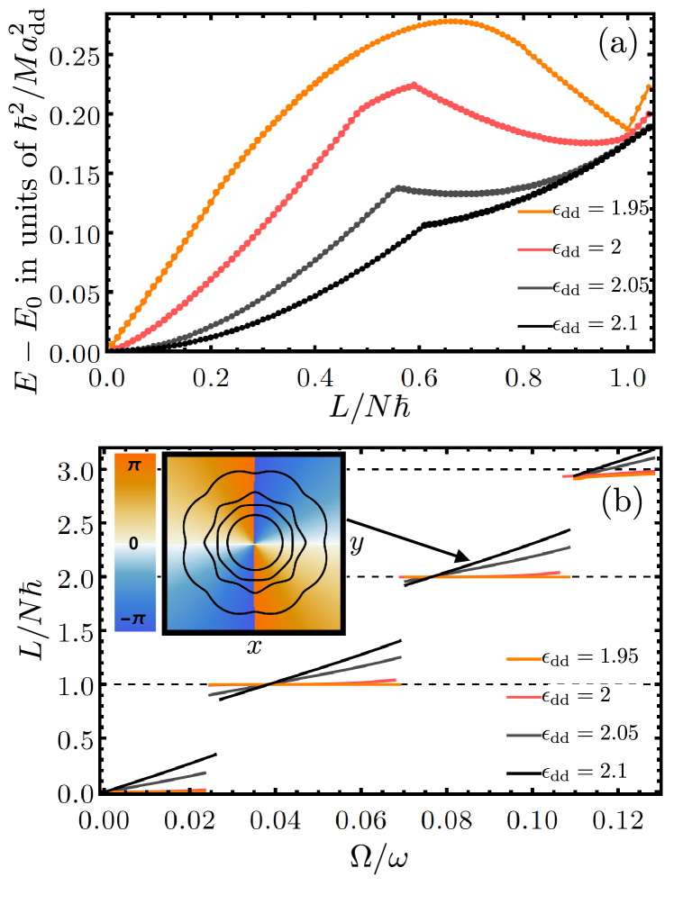
The observation of becomes possible because the density drops to zero at the location of a strong barrier. A weak barrier that maintains non-zero density between the rings favors the formation of a vortex at . The overall behavior of the yrast lines, which support persistent currents at their minima and display kinks in the SS regime, is similar to the case of separated rings [compare Fig. 3(a) and Fig. 4(a)]. In particular, we highlight the behavior for when . The absence of a minimum in the yrast line indicates that persistent currents cannot form in this system. Nevertheless, the rotational ground states can still host vortices [ Fig. 4(b)].
Depending on the rotation frequency , the vortex may manifest either as a CV or as a different type of JV distinct from . That the vortex is a CV within the interval is evident from the integer value of the angular momentum, shared by all particles in the condensate, for [see Fig. 4(b)]. In the SS regime, the same vortex remains a CV, though with a reduced superfluid angular momentum. The critical rotation frequencies for the system at which the charge of the vortex changes from to are given as the solutions of the transcendental equation
| (6) |
We note that the mean value is calculated from the wave function which, in general, depends on all parameters of the system.
Let us now analyze the shape of the yrast line. The is linear for small value of and around the minima. We can understand the behavior at small by assuming that the vortex is far from the condensate, such that its core does not interfere with the condensate density. In this scenario, the wave function can be approximated as
| (7) |
where we assume the vortex to enter on the x-axis, such that its position in the xy-plane is given by , and is the local density. Inserting Eq. (7) in the energy functional and expanding linearly around , we obtain
| (8) |
which is valid as long as . To understand the linear behavior near the minimum energy, where the vortex is located at the center and the interaction between the vortex and condensate can be neglected, we again take Eq. (7) as an ansatz and expand linearly around ,
| (9) |
For arbitrary values of , the energy of the vortex consists of two parts: the kinetic energy and the interaction energy which arises from the density depletion when the vortex penetrates the condensate. The latter is a concave parabolic function of . For a SS the situation is entirely different. An additional term in the kinetic energy emerges from the solid body rotation, reading as where . The contribution of the interaction energy decreases with decreasing , because the vortex can pass through interstitial region between the density maxima and therefore minimizing the interaction.
In order to calculate the yrast line for the SS state, let us decompose the total angular momentum into two parts, namely a SF part and a SS part . The yrast line can then be constructed by
| (10) |
This function has a kink at
Further, the yrast line has a metastable state at as long as , where . For the , and , and therefore no-metasble state is observed in Fig. 4(b). We also point out that all equations mentioned above are also valid for the yrast lines of the separated ring cases if we exchange , and by , and , where means integration over the outer ring only and is the superfluid fraction of the outer ring. The latter can be obtained by calculating the angular momentum and the moment of inertia for the outer ring only. Furthermore, for a single-ring system with tight confinement and localized density, the relation holds, indicating that the kink appears at . In contrast, for the double-ring system, the kink position can be varied significantly by tuning and , thereby allowing the system to host a wider range of vortex configurations.
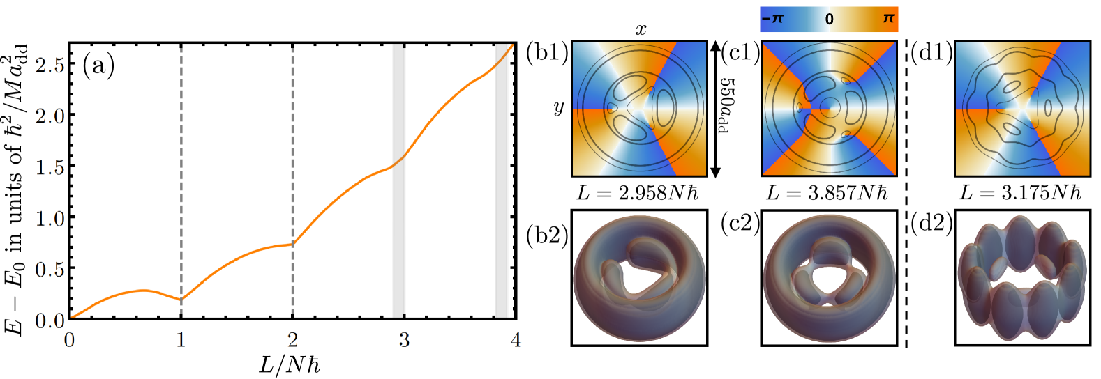
The most intriguing effects of the connected-ring geometry emerge at high angular momentum states. At these higher angular momentum states, rotation alone induces density modulation in the inner condensate, transforming it into a SS state with three localized density sites. The presence of SS is reflected in the slope of the angular momentum, detectable even for ; see Fig. 4(b). To gain deeper insight into this phenomenon, we calculate the yrast line up to high angular momentum states, , for [Fig. 5(a)]. Two types of topological defects can be identified in the dispersion relation. The first two dashed lines, indicating kinks at , correspond to CVs. In any rotating frame, , the positions of these kinks remain fixed. Additionally, we observe two defects with angular momenta indicated by the gray regions. In a rotating frame, these defects can form a global minimum at values , which satisfy , meaning that the position of the minimum depends on the rotation frequency at which the vortices are nucleated. This behavior is possible only if solid-body rotation occurs due to the formation of localized density sites, with the associated vortices being , which form at the junctions between these sites. The ensuing sites and three at the junctions between these sites for and are shown in Figs. 5(b1)-(b2) and Figs. 5(d1)-(d2), respectively. The one with correspond to the SS with a density modulation in both inner and outer rings. We show that adding the next vortex as a CV is energetically favorable if the angular momentum becomes larger such as [Figs. 5(c1)-(c2)], and thus, enabling the coexistence of CV and .
We note that the rotation-induced SS also occurs in a single-ring configuration [92] and arises from the fact that, in the rotating frame, the energy at the roton minimum can satisfy the condition by tuning . Notably, this provides an alternative protocol for generating an SS state, independent of controlling . This mechanism is particularly relevant in our double-ring system, where modulation can appear in either the outer or inner ring, depending on the presence of inter-ring density connection. The emergence of modulation in the inner ring is intrinsically linked to the and represents one of the key highlights of our work.
III.2.3 - diagram
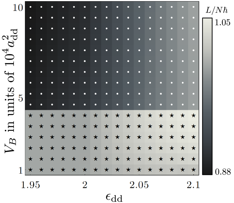
We now examine how the Gaussian barrier influences the presence of and CVs for different interaction strengths . We fix the rotation frequency at and calculate the total angular momentum as a function of and , as shown in Fig. 6. In our system, CVs exist when , while are present when . We observe a critical barrier strength that separates the regions of the phase diagram indicating and CVs. By comparing this with the inset in [Figs. 2] we see that the density for this barrier strength is non-zero. Consequently, the creation of the -core requires kinetic energy, but still the total energy of the is smaller than the total kinetic energy of a CV. For the parameter grids in [Figs. 6] we do not see a dependency of on . The SF-SS phase transition is also evident in Fig. 6. For , in the SF state, the angular momentum of the CV is constant and equal to . In the SS phase, the angular momentum of the CV is no longer constant due to the contribution from the solid part of the system, which increases with larger . In the case of a , this effect is reinforced by the increasing population of the outer ring. This result once again confirms that the barrier is the cause for the nucleation of .
III.3 Vortex Detection
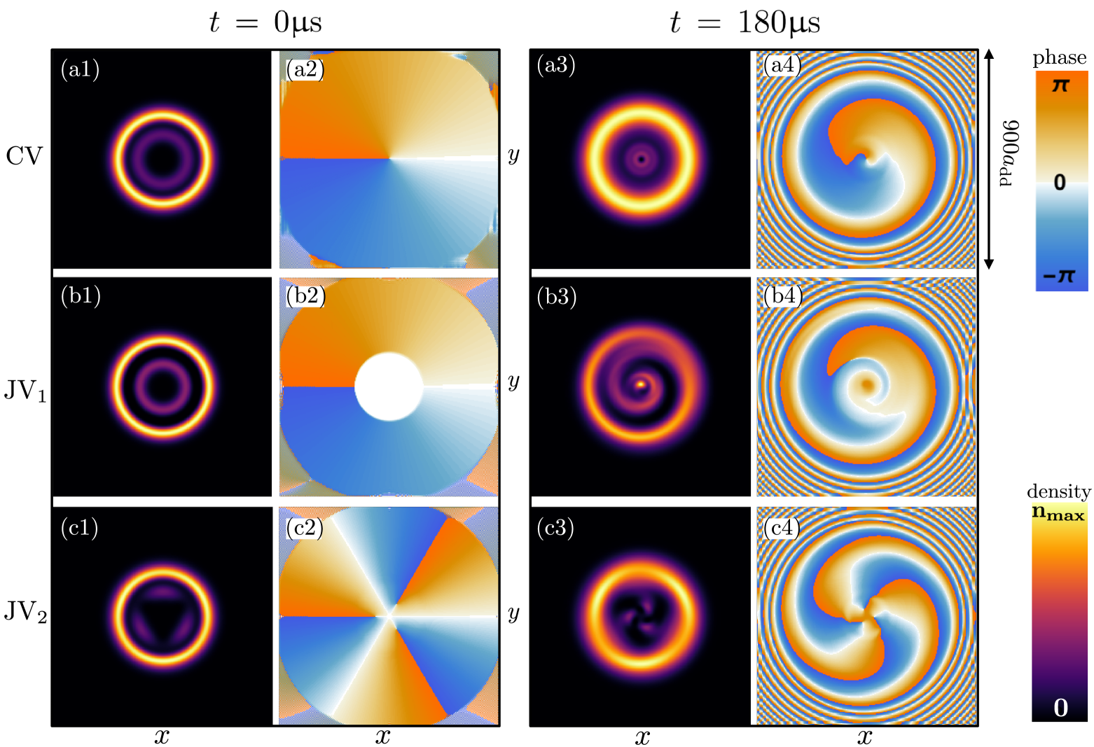
In the preceding sections, we have demonstrated how JVs and CVs can be nucleated in a double-ring system. This system is particularly advantageous as it provides a practical method for detecting these vortices once they are generated. The corresponding protocol involves interfering condensate parts located in the inner and outer rings by switching off the trap and monitoring the resulting interference pattern. Since JVs and CVs exhibit distinct phase profiles, they are expected to produce discernible density patterns during expansion. We illustrate such expansion dynamics in Fig. 7 focusing only SF with .
The initial 2D density profiles and phase profile for a CV are highlighted in Fig. 7(a1) and (a2), respectively. Such initial state is created with and . Here, both the inner and outer condensates contain one complete phase winding, resulting in concentric circular density patterns after interference [Figs. 7(a3)-(a4)]. Such density and phase profiles have to be contrasted when a is present in the system for ; see Figs. 7(b1)-(b4). The inner ring posses a unform phase whereas the phase winds over in the outer ring owing to single . Consequently, after interference, the density develops a single spiral around the center. However, the presence of density modulation in the inner ring, which is otherwise an SF in the absence of rotation, indicates the existence of . This is further confirmed by the interference pattern, where we observe that modulated density structures persist in the inner region of the condensate, with the located between these structures [Figs. 7(c3)-(c4)]. Thus, this interference protocol not only confirms the existence of a defect but also reveals the phase distribution resulting from its specific position.
IV Conclusions
In conclusion, we have investigated the non-rotational and rotational properties of dipolar atoms in coplanar and concentric double rings. We have specifically focused on two different cases: one where the rings are connected by density overlap and another where they are separated. Our findings reveal a population imbalance between the inner and outer rings, in contrast to non-dipolar systems. Notably, the outer ring exhibits a proclivity for spontaneous density modulation, indicative of a SS state, regardless of the strength of the barrier forming the double-ring structure.
We have studied the rotational properties of the system and demonstrated the existence of a persistent current by calculating its energy as a function of angular momentum. The persistent current is accompanied by the formation of topological structures, specifically and , which appear in the separated and connected rings, respectively. We have delineated their regions of existence in a diagram by calculating angular momentum as a function of interaction and barrier strength. Specifically, we have identified multiple topological defects, such as and combination of and , which emerge in the separated ring case at higher rotational frequencies.
One of the intriguing features of our system lies in its connection to rotation-induced SS state formation. We have found that, for relatively small angular momentum, rotation can induce density modulation in the outer ring, transforming an otherwise SF state into an SS state. Interestingly, in the case of connected rings, the inner condensate forms three localized density sites at high angular momentum states, where three vortices are nucleated at the junctions between the localized density sites. These vortices, which we refer to as , are associated with the spontaneously formed localized density sites induced by rotation and are unique to our double-ring dipolar system. Finally, by utilizing an interferometric protocols, we have demonstrated how these different topological structures can be detected in the experiment.
There are several extensions of the present work worth pursuing in future research. A straightforward extension would be to study the underlying collective excitation spectra of the double-ring system, particularly around the critical point of the phase transition. Additionally, it would be interesting to explore the signature of in the excitation spectrum. Another intriguing direction would be to investigate the parameter regime where density modulation occurs in both rings in the non-rotating supersolid state. This would enable the study of shear-wave propagation across the azimuth of the rings by suddenly altering the distance between the inter-ring localized density sites. Furthermore, investigating finite-temperature properties [103] in the context of this setup would be equally compelling.
ACKNOWLEDGMENTS
We thank Thomas Bland, Philipp Stürmer, Tiziano Arnone Cardinale, Deepak Gaur, Lila Chergui and Stuttgart Dipolar Gases group for fruitful discussions. M.S., K.M. and S.R. acknowledge financial support from the Knut and Alice Wallenberg Foundation (Grant No. KAW 2018.0217 and KAW2023.0322) and the Swedish Research Council (Grant No. 2022-03654). T.P. acknowledges support from the European Research Council (ERC) (grant agreement No. 101019739).
Appendix A Computational Details
Here, we detail the numerical simulations used to obtain the results described in the main text. We numerically solve the the extended Gross-Pitaevskii equation (eGPE) obtained from the functional derivative of the energy density function. The eGPE equation is cast into a dimensionless form in our simulations by rescaling the length, the time by length and time scales, and , respectively. Thereafter, we employ the split-time Fourier spectral method to solve the resulting equation [104, 105]. The stationary state of the system is obtained through imaginary time propagation, while the dynamical simulation is performed in real time. At each imaginary time step, we preserve the normalization of the wave function, and convergence is reached when the relative deviation of the wave function at every grid point and the angular momentum and energy between consecutive time steps are smaller than and , respectively. It should be noted that calculating the stationary state solution of the eGPE is an involved task due to many close-lying local minima in the energy surface, which necessitates extensive sampling over many different initial conditions to identify the most probable lowest-energy solutions. Our simulations are carried out in a 3D box characterized by a grid corresponding to ( for the simulation of interferometric protocol). The employed spatial discretizations (grid spacing) refers to with for the calculations of rotating and non-rotating ground states ( for the simulations of interferometric protocol), while the time step of the numerical integration is .
References
- Gross [1957] E. P. Gross, Phys. Rev. 106, 161 (1957).
- Bloch [1973] F. Bloch, Phys. Rev. A 7, 2187 (1973).
- Leggett [1999] A. J. Leggett, Rev. Mod. Phys. 71, S318 (1999).
- Fetter [2009] A. L. Fetter, Rev. Mod. Phys. 81, 647 (2009).
- Bloch [1965] F. Bloch, Phys. Rev. 137, A787 (1965).
- Matveev et al. [2002] K. A. Matveev, A. I. Larkin, and L. I. Glazman, Phys. Rev. Lett. 89, 096802 (2002).
- Ryu et al. [2007] C. Ryu, M. F. Andersen, P. Cladé, V. Natarajan, K. Helmerson, and W. D. Phillips, Phys. Rev. Lett. 99, 260401 (2007).
- Ramanathan et al. [2011] A. Ramanathan, K. C. Wright, S. R. Muniz, M. Zelan, W. T. Hill, C. J. Lobb, K. Helmerson, W. D. Phillips, and G. K. Campbell, Phys. Rev. Lett. 106, 130401 (2011).
- Moulder et al. [2012] S. Moulder, S. Beattie, R. P. Smith, N. Tammuz, and Z. Hadzibabic, Phys. Rev. A 86, 013629 (2012).
- Wright et al. [2013] K. C. Wright, R. B. Blakestad, C. J. Lobb, W. D. Phillips, and G. K. Campbell, Phys. Rev. Lett. 110, 025302 (2013).
- Beattie et al. [2013] S. Beattie, S. Moulder, R. J. Fletcher, and Z. Hadzibabic, Phys. Rev. Lett. 110, 025301 (2013).
- Murray et al. [2013] N. Murray, M. Krygier, M. Edwards, K. C. Wright, G. K. Campbell, and C. W. Clark, Phys. Rev. A 88, 053615 (2013).
- Eckel et al. [2014] S. Eckel, J. G. Lee, F. Jendrzejewski, N. Murray, C. W. Clark, C. J. Lobb, W. D. Phillips, M. Edwards, and G. K. Campbell, Nature 506, 200 (2014).
- Jendrzejewski et al. [2014] F. Jendrzejewski, S. Eckel, N. Murray, C. Lanier, M. Edwards, C. J. Lobb, and G. K. Campbell, Phys. Rev. Lett. 113, 045305 (2014).
- Guo et al. [2020] Y. Guo, R. Dubessy, M. d. G. de Herve, A. Kumar, T. Badr, A. Perrin, L. Longchambon, and H. Perrin, Phys. Rev. Lett. 124, 025301 (2020).
- Polo et al. [2024] J. Polo, W. J. Chetcuti, T. Haug, A. Minguzzi, K. Wright, and L. Amico, arXiv:2410.17318 (2024).
- Josephson [1962] B. D. Josephson, Phys. Lett. 1, 251 (1962).
- Smerzi et al. [1997] A. Smerzi, S. Fantoni, S. Giovanazzi, and S. R. Shenoy, Phys. Rev. Lett. 79, 4950 (1997).
- Marino et al. [1999] I. Marino, S. Raghavan, S. Fantoni, S. R. Shenoy, and A. Smerzi, Phys. Rev. A 60, 487 (1999).
- Albiez et al. [2005] M. Albiez, R. Gati, J. Fölling, S. Hunsmann, M. Cristiani, and M. K. Oberthaler, Phys. Rev. Lett. 95, 010402 (2005).
- Gati and Oberthaler [2007] R. Gati and M. K. Oberthaler, Journal of Physics B: Atomic, Molecular and Optical Physics 40, R61 (2007).
- Levy et al. [2007] S. Levy, E. Lahoud, I. Shomroni, and J. Steinhauer, Nature 449, 579 (2007).
- LeBlanc et al. [2011] L. J. LeBlanc, A. B. Bardon, J. McKeever, M. H. T. Extavour, D. Jervis, J. H. Thywissen, F. Piazza, and A. Smerzi, Phys. Rev. Lett. 106, 025302 (2011).
- Gallemí et al. [2015] A. Gallemí, A. M. Mateo, R. Mayol, and M. Guilleumas, New Journal of Physics 18, 015003 (2015).
- Gallemí et al. [2016] A. Gallemí, M. Guilleumas, R. Mayol, and A. M. n. Mateo, Phys. Rev. A 93, 033618 (2016).
- Spagnolli et al. [2017] G. Spagnolli, G. Semeghini, L. Masi, G. Ferioli, A. Trenkwalder, S. Coop, M. Landini, L. Pezzè, G. Modugno, M. Inguscio, A. Smerzi, and M. Fattori, Phys. Rev. Lett. 118, 230403 (2017).
- Pigneur et al. [2018] M. Pigneur, T. Berrada, M. Bonneau, T. Schumm, E. Demler, and J. Schmiedmayer, Phys. Rev. Lett. 120, 173601 (2018).
- Lesanovsky and von Klitzing [2007] I. Lesanovsky and W. von Klitzing, Phys. Rev. Lett. 98, 050401 (2007).
- Brand et al. [2009] J. Brand, T. J. Haigh, and U. Zülicke, Phys. Rev. A 80, 011602 (2009).
- Brand et al. [2010] J. Brand, T. J. Haigh, and U. Zülicke, Phys. Rev. A 81, 025602 (2010).
- Malet et al. [2010] F. Malet, G. M. Kavoulakis, and S. M. Reimann, Phys. Rev. A 81, 013630 (2010).
- Aghamalyan et al. [2013] D. Aghamalyan, L. Amico, and L. C. Kwek, Phys. Rev. A 88, 063627 (2013).
- Zhang et al. [2013] X.-F. Zhang, B. Li, and S.-G. Zhang, Laser Physics 23, 105501 (2013).
- Su et al. [2013] S.-W. Su, S.-C. Gou, A. Bradley, O. Fialko, and J. Brand, Phys. Rev. Lett. 110, 215302 (2013).
- Polo et al. [2016] J. Polo, A. Benseny, T. Busch, V. Ahufinger, and J. Mompart, New Journal of Physics 18, 015010 (2016).
- Bland et al. [2022a] T. Bland, I. V. Yatsuta, M. Edwards, Y. O. Nikolaieva, A. O. Oliinyk, A. I. Yakimenko, and N. P. Proukakis, Phys. Rev. Res. 4, 043171 (2022a).
- Bazhan et al. [2022] N. Bazhan, A. Svetlichnyi, D. Pfeiffer, D. Derr, G. Birkl, and A. Yakimenko, Phys. Rev. A 106, 043305 (2022).
- Borysenko et al. [2024] Y. Borysenko, N. Bazhan, O. Prykhodko, D. Pfeiffer, L. Lind, G. Birkl, and A. Yakimenko, arXiv:2411.09186 (2024).
- Chaika et al. [2024] A. Chaika, A. O. Oliinyk, I. V. Yatsuta, N. P. Proukakis, M. Edwards, A. I. Yakimenko, and T. Bland, “Acceleration-induced transport of quantum vortices in joined atomtronic circuits,” (2024), arXiv:2410.23818 [cond-mat.quant-gas] .
- Roditchev et al. [2015] D. Roditchev, C. Brun, L. Serrier-Garcia, J. C. Cuevas, V. H. L. Bessa, M. V. Milošević, F. Debontridder, V. Stolyarov, and T. Cren, Nat. Phys. 11, 332 (2015).
- Caputo et al. [2019] D. Caputo, N. Bobrovska, D. Ballarini, M. Matuszewski, M. De Giorgi, L. Dominici, K. West, L. N. Pfeiffer, G. Gigli, and D. Sanvitto, Nat. Photonics 13, 488 (2019).
- Kaurov and Kuklov [2005] V. M. Kaurov and A. B. Kuklov, Phys. Rev. A 71, 011601 (2005).
- Montgomery et al. [2013] T. W. A. Montgomery, W. Li, and T. M. Fromhold, Phys. Rev. Lett. 111, 105302 (2013).
- Oliinyk et al. [2020] A. Oliinyk, B. Malomed, and A. Yakimenko, Commun. Nonlinear Sci. Numer. Simul. 83, 105113 (2020).
- Tononi et al. [2024] A. Tononi, L. Salasnich, and A. Yakimenko, AVS Quantum Science 6, 030502 (2024).
- Lahaye et al. [2009] T. Lahaye, C. Menotti, L. Santos, M. Lewenstein, and T. Pfau, Reports on Progress in Physics 72, 126401 (2009).
- Böttcher et al. [2020] F. Böttcher, J.-N. Schmidt, J. Hertkorn, K. S. H. Ng, S. D. Graham, M. Guo, T. Langen, and T. Pfau, Reports on Progress in Physics 84, 012403 (2020).
- Chomaz et al. [2022] L. Chomaz, I. Ferrier-Barbut, F. Ferlaino, B. Laburthe-Tolra, B. L. Lev, and T. Pfau, Reports on Progress in Physics 86, 026401 (2022).
- Mukherjee et al. [2023] K. Mukherjee, T. A. Cardinale, L. Chergui, P. Sturmer, and S. Reimann, Eur Phys J Spec Top (2023), 10.1140/epjs/s11734-023-00991-6.
- Griesmaier et al. [2005] A. Griesmaier, J. Werner, S. Hensler, J. Stuhler, and T. Pfau, Phys. Rev. Lett. 94, 160401 (2005).
- Stuhler et al. [2005] J. Stuhler, A. Griesmaier, T. Koch, M. Fattori, T. Pfau, S. Giovanazzi, P. Pedri, and L. Santos, Phys. Rev. Lett. 95, 150406 (2005).
- Lu et al. [2010] H.-Y. Lu, H. Lu, J.-N. Zhang, R.-Z. Qiu, H. Pu, and S. Yi, Phys. Rev. A 82, 023622 (2010).
- Lu et al. [2011] M. Lu, N. Q. Burdick, S. H. Youn, and B. L. Lev, Phys. Rev. Lett. 107, 190401 (2011).
- Aikawa et al. [2012] K. Aikawa, A. Frisch, M. Mark, S. Baier, A. Rietzler, R. Grimm, and F. Ferlaino, Phys. Rev. Lett. 108, 210401 (2012).
- Miyazawa et al. [2022] Y. Miyazawa, R. Inoue, H. Matsui, G. Nomura, and M. Kozuma, Phys. Rev. Lett. 129, 223401 (2022).
- Kadau et al. [2016] H. Kadau, M. Schmitt, M. Wenzel, C. Wink, T. Maier, I. Ferrier-Barbut, and T. Pfau, Nature 530, 194–197 (2016).
- Ferrier-Barbut et al. [2016] I. Ferrier-Barbut, H. Kadau, M. Schmitt, M. Wenzel, and T. Pfau, Phys. Rev. Lett. 116, 215301 (2016).
- Böttcher et al. [2019] F. Böttcher, J.-N. Schmidt, M. Wenzel, J. Hertkorn, M. Guo, T. Langen, and T. Pfau, Phys. Rev. X 9, 011051 (2019).
- Tanzi et al. [2019a] L. Tanzi, E. Lucioni, F. Famà, J. Catani, A. Fioretti, C. Gabbanini, R. N. Bisset, L. Santos, and G. Modugno, Phys. Rev. Lett. 122, 130405 (2019a).
- Chomaz et al. [2019] L. Chomaz, D. Petter, P. Ilzhöfer, G. Natale, A. Trautmann, C. Politi, G. Durastante, R. M. W. van Bijnen, A. Patscheider, M. Sohmen, M. J. Mark, and F. Ferlaino, Phys. Rev. X 9, 021012 (2019).
- Norcia et al. [2021] M. A. Norcia, C. Politi, L. Klaus, E. Poli, M. Sohmen, M. J. Mark, R. N. Bisset, L. Santos, and F. Ferlaino, Nature 596, 357 (2021).
- Gross [1958] E. P. Gross, Annals of Physics 4, 57 (1958).
- Yang [1962] C. N. Yang, Rev. Mod. Phys. 34, 694 (1962).
- Chester [1970] G. V. Chester, Phys. Rev. A 2, 256 (1970).
- Leggett [1970] A. J. Leggett, Phys. Rev. Lett. 25, 1543 (1970).
- Boninsegni and Prokof’ev [2012] M. Boninsegni and N. V. Prokof’ev, Rev. Mod. Phys. 84, 759 (2012).
- Guo et al. [2019] M. Guo, F. Böttcher, J. Hertkorn, J.-N. Schmidt, M. Wenzel, H. P. Büchler, T. Langen, and T. Pfau, Nature 574, 386–389 (2019).
- Natale et al. [2019] G. Natale, R. M. W. van Bijnen, A. Patscheider, D. Petter, M. J. Mark, L. Chomaz, and F. Ferlaino, Phys. Rev. Lett. 123, 050402 (2019).
- Hertkorn et al. [2019] J. Hertkorn, F. Böttcher, M. Guo, J. N. Schmidt, T. Langen, H. P. Büchler, and T. Pfau, Phys. Rev. Lett. 123, 193002 (2019).
- Schmidt et al. [2021] J.-N. Schmidt, J. Hertkorn, M. Guo, F. Böttcher, M. Schmidt, K. S. H. Ng, S. D. Graham, T. Langen, M. Zwierlein, and T. Pfau, Phys. Rev. Lett. 126, 193002 (2021).
- Hertkorn et al. [2021a] J. Hertkorn, J.-N. Schmidt, M. Guo, F. Böttcher, K. S. H. Ng, S. D. Graham, P. Uerlings, H. P. Büchler, T. Langen, M. Zwierlein, and T. Pfau, Phys. Rev. Lett. 127, 155301 (2021a).
- Hertkorn et al. [2021b] J. Hertkorn, J.-N. Schmidt, F. Böttcher, M. Guo, M. Schmidt, K. S. H. Ng, S. D. Graham, H. P. Büchler, T. Langen, M. Zwierlein, and T. Pfau, Phys. Rev. X 11, 011037 (2021b).
- Bühler et al. [2023] C. Bühler, T. Ilg, and H. P. Büchler, Phys. Rev. Res. 5, 033092 (2023).
- Poli et al. [2024] E. Poli, D. Baillie, F. Ferlaino, and P. B. Blakie, Phys. Rev. A 110, 053301 (2024).
- Tanzi et al. [2019b] L. Tanzi, S. M. Roccuzzo, E. Lucioni, F. Fama, A. Fioretti, C. Gabbanini, G. Modugno, A. Recati, and S. Stringari, Nature 574, 382–385 (2019b).
- Ilzhöfer et al. [2021] P. Ilzhöfer, M. Sohmen, G. Durastante, C. Politi, A. Trautmann, G. Natale, G. Morpurgo, T. Giamarchi, L. Chomaz, M. J. Mark, and F. Ferlaino, Nature Phys. 17, 356–361 (2021).
- Sohmen et al. [2021] M. Sohmen, C. Politi, L. Klaus, L. Chomaz, M. J. Mark, M. A. Norcia, and F. Ferlaino, Phys. Rev. Lett. 126, 233401 (2021).
- Bland et al. [2022b] T. Bland, E. Poli, C. Politi, L. Klaus, M. A. Norcia, F. Ferlaino, L. Santos, and R. N. Bisset, Phys. Rev. Lett. 128, 195302 (2022b).
- Alaña et al. [2023] A. Alaña, I. n. L. Egusquiza, and M. Modugno, Phys. Rev. A 108, 033316 (2023).
- Mukherjee and Reimann [2023] K. Mukherjee and S. M. Reimann, Phys. Rev. A 107, 043319 (2023).
- Mistakidis et al. [2024] S. I. Mistakidis, K. Mukherjee, S. M. Reimann, and H. R. Sadeghpour, Phys. Rev. A 110, 013323 (2024).
- Roccuzzo et al. [2020] S. M. Roccuzzo, A. Gallemí, A. Recati, and S. Stringari, Phys. Rev. Lett. 124, 045702 (2020).
- Gallemí et al. [2020] A. Gallemí, S. M. Roccuzzo, S. Stringari, and A. Recati, Phys. Rev. A 102, 023322 (2020).
- Šindik et al. [2022] M. Šindik, A. Recati, S. M. Roccuzzo, L. Santos, and S. Stringari, Phys. Rev. A 106, L061303 (2022).
- Klaus et al. [2022] L. Klaus, T. Bland, E. Poli, C. Politi, G. Lamporesi, E. Casotti, R. N. Bisset, M. J. Mark, and F. Ferlaino, Nature Physics 18 (2022), 10.1038/s41567-022-01793-8.
- Casotti et al. [2024] E. Casotti, E. Poli, L. Klaus, A. Litvinov, C. Ulm, C. Politi, M. J. Mark, T. Bland, and F. Ferlaino, Nature 635, 327 (2024).
- Abad et al. [2011] M. Abad, M. Guilleumas, R. Mayol, M. Pi, and D. M. Jezek, Europhysics Letters 94, 10004 (2011).
- Biagioni et al. [2024] G. Biagioni, N. Antolini, B. Donelli, L. Pezzè, A. Smerzi, M. Fattori, A. Fioretti, C. Gabbanini, M. Inguscio, L. Tanzi, and G. Modugno, Nature 629, 773 (2024).
- Platt et al. [2024] L. M. Platt, D. Baillie, and P. B. Blakie, arXiv:2412.15552 (2024).
- Donelli et al. [2025] B. Donelli, N. Antolini, G. Biagioni, M. Fattori, A. Fioretti, C. Gabbanini, M. Inguscio, L. Tanzi, G. Modugno, A. Smerzi, and L. Pezzè, arXiv:2501.17142 (2025).
- Alaña et al. [2025] A. Alaña, M. Modugno, P. Capuzzi, and D. M. Jezek, arXiv:2501.08739 (2025).
- Tengstrand et al. [2021] M. N. Tengstrand, D. Boholm, R. Sachdeva, J. Bengtsson, and S. M. Reimann, Phys. Rev. A 103, 013313 (2021).
- Nilsson Tengstrand et al. [2023] M. Nilsson Tengstrand, P. Stürmer, J. Ribbing, and S. M. Reimann, Phys. Rev. A 107, 063316 (2023).
- Šindik et al. [2024] M. Šindik, T. Zawiślak, A. Recati, and S. Stringari, Phys. Rev. Lett. 132, 146001 (2024).
- Hertkorn et al. [2024] J. Hertkorn, P. Stürmer, K. Mukherjee, K. S. H. Ng, P. Uerlings, F. Hellstern, L. Lavoine, S. M. Reimann, T. Pfau, and R. Klemt, Phys. Rev. Res. 6, L042056 (2024).
- Lima and Pelster [2011] A. R. P. Lima and A. Pelster, Phys. Rev. A 84, 041604 (2011).
- Lima and Pelster [2012] A. R. P. Lima and A. Pelster, Phys. Rev. A 86, 063609 (2012).
- Mottelson [1999] B. Mottelson, Phys. Rev. Lett. 83, 2695 (1999).
- de Voigt et al. [1983] M. J. A. de Voigt, J. Dudek, and Z. Szymański, Rev. Mod. Phys. 55, 949 (1983).
- Komineas et al. [2005] S. Komineas, N. R. Cooper, and N. Papanicolaou, Phys. Rev. A 72, 053624 (2005).
- Kärkkäinen et al. [2007] K. Kärkkäinen, J. Christensson, G. Reinisch, G. M. Kavoulakis, and S. M. Reimann, Phys. Rev. A 76, 043627 (2007).
- Leggett [1998] A. J. Leggett, J. Stat. Phys. 93, 927 (1998).
- Sánchez-Baena et al. [2022] J. Sánchez-Baena, C. Politi, F. Maucher, F. Ferlaino, and T. Pohl, Nat. Commun. 14, 1868 (2022).
- Bao et al. [2003a] W. Bao, D. Jaksch, and P. A. Markowich, Journal of Computational Physics 187, 318 (2003a).
- Bao et al. [2003b] W. Bao, S. Jin, and P. A. Markowich, SIAM Journal on Scientific Computing 25, 27 (2003b), https://doi.org/10.1137/S1064827501393253 .