[1]Navid Vafaei-Najafabadi 1]Department of Physics and Astronomy, Stony Brook University, Stony Brook, USA 2]University of Rochester, Laboratory for Laser Energetics, Rochester, New York 14623, USA 3] Department of Electrical and Computer Engineering, University of California, Los Angeles, California 90095, USA 4]Accelerator Test Facility, Brookhaven National Laboratory, Upton, NY 11973, USA 5]Department of Physics, University of Texas at Austin, Austin TX 78712, USA
Collider-quality electron bunches from an all-optical plasma photoinjector
Abstract
We present a novel approach for generating collider-quality electron bunches using a plasma photoinjector. The approach leverages recently developed techniques for the spatiotemporal control of laser pulses to produce a moving ionization front in a nonlinear plasma wave. The moving ionization front generates an electron bunch with a current profile that balances the longitudinal electric field of an electron beam-driven plasma wave, creating a uniform accelerating field across the bunch. Particle-in-cell (PIC) simulations of the ionization stage show the formation of an electron bunch with 220 pC charge and low emittance ( nm-rad, nm-rad). Quasistatic PIC simulations of the acceleration stage show that the bunch is efficiently accelerated to 20 GeV over 2-meters with a final energy spread of less than 1% and emittances of nm-rad and nm-rad. This high-quality electron bunch meets the requirements outlined by the Snowmass process for intermediate-energy colliders and compares favorably to the beam quality of proposed and existing accelerator facilities. The results establish the feasibility of plasma photoinjectors for future collider applications making a significant step towards the realization of high-luminosity, compact accelerators for particle physics research.
Two decades ago, the so-called “dream-beam” papers reported the first demonstration of monoenergetic relativistic electron bunches from the interaction of ultrashort laser pulses with plasma [1, 2, 3]. In the years since, the plasma accelerator community has made great strides towards generating bunches with potential application to a collider, which would fulfill the original dream of replacing the MV/m fields of radio frequency cavities with the GV/m fields of nonlinear plasma waves. As part of the Snowmass process, where the high energy physics community outlines their priorities for the field, the plasma accelerator community laid out a vision for plasma-based colliders at TeV-scale energies [4] as well as an intermediate demonstration facility at 10-50 GeV[5]. Realizing the vision of a plasma-based collider requires electron bunches with hundreds of pC of charge at a normalized emittance below 100 nanometers [4, 5]. In addition, the energy spread must be less than 1% for compatibility with the final focusing section of a particle collider and to maximize the cross-section of collisions. While the plasma accelerator community has explored innovative ideas for producing such bunches [6], simultaneous achievement of all three requirements—high charge, low emittance, and low energy spread—has proved elusive [7].
In this paper, we demonstrate how emerging techniques for controlling the spatiotemporal properties of a laser pulse enable an all-optical “plasma photoinjector” that generates an electron bunch satisfying all requirements for plasma collider applications. The approach for producing collider-quality electron bunches, illustrated in Fig. 1, is based on the two-color ionization injection mechanism in a laser wakefield accelerator (LWFA) [8, 9, 10], wherein a long-wavelength laser pulse serves as the “driver” of a plasma wave, and a second, shorter-wavelength laser pulse acts as the “injector.” An injector pulse focused by an ideal lens, as was used in previous work, co-propagates with the plasma wave, but remains a fixed distance behind it, which constrains properties of the injected bunch. Here, a “flying focus” injector pulse is used instead. The flying focus pulse features a dynamic focal point, which allows the peak intensity to move with respect to the plasma wave. The moving ionization front produced by the flying focus leads to the formation of a high-charge, low-emittance bunch with a longitudinal current that decreases nearly linearly from its leading to trailing edge (Fig. 1). This trapezoidal current profile is critical to achieving a low energy spread while the bunch is further accelerated to high energies. To illustrate this, the bunch generated by the photoinjector is accelerated in a plasma wakefield accelerator to 20 GeV. The parameters of the plasma wakefield accelerator are selected so that the trapezoidal profile produced by the photoinjector flattens the longitudinal electric field, ensuring uniform acceleration across the bunch and a small final energy spread.
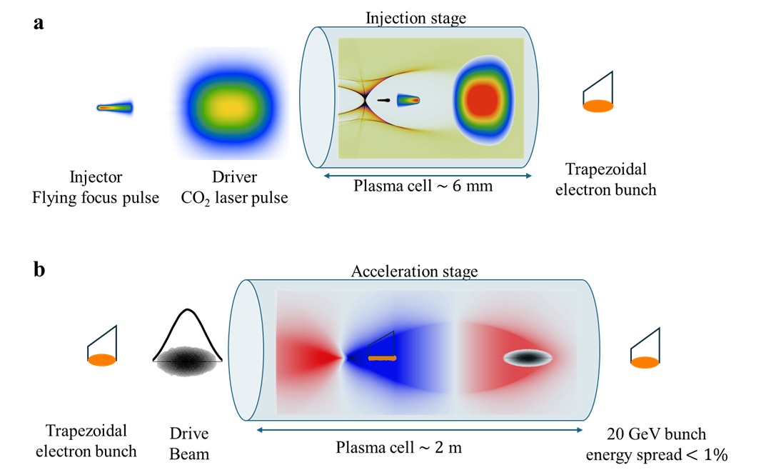
Figure 2 illustrates the underlying physics of two-color ionization injection and contrasts a typical conventional lens configuration with the novel flying focus configuration introduced here (see Methods for simulation details). Both configurations use the same CO2 laser pulse as the driver (see Table 1 for parameters). The CO2 pulse propagates through and ionizes a gas, freeing the outer shell electrons and forming a plasma. The ponderomotive force of the pulse then pushes the plasma electrons away from the propagation axis. The ions, which remain stationary over the timescale of the interaction, pull the displaced electrons back towards the axis, creating a region of positive charge density surrounded by a sheath of electrons. The accelerating field within this nonlinear plasma wave, commonly referred to as the plasma bubble [11], exceeds 10 GV/m, which is hundreds of times larger than the conventional accelerators currently in operation.
A long-wave infrared laser pulse such as a CO2 pulse with a wavelength is an ideal driver for two-color ionization injection. This is because the magnitude of the accelerating field increases with the normalized vector potential of the pulse, , where is the intensity. A strongly nonlinear plasma wave is expected when (The CO2 laser pulse in Fig. 2 has an ). The scaling allows the CO2 pulse to reach these values of at an intensity that is a hundred times smaller than would be required with a near-infrared pulse, such as produced by typically used Ti:Sapphire lasers. The intensity of the CO2 pulse is however high enough to free the outer shell electrons of a background gas, e.g., the first eight levels of krypton, producing Kr8+ (See Methods section).
To initiate ionization injection, a short-wavelength injector pulse ( ) is focused behind the driver to a peak of 0.17, which is selected so that the intensity exceeds the ionization threshold of Kr8+. Note that although the of the injector pulse is much smaller than that of the CO2 pulse, it has a much higher intensity due to its shorter wavelength. The injector pulse frees the outer Kr8+ electrons in the accelerating phase of the plasma wave. These electrons are then accelerated to relativistic energies and trapped in the wave.
This configuration, in which a driver partially ionizes a gas and excites a large-amplitude plasma wave while an injector triggers additional ionization within the wave, is fundamental to two-color ionization injection. The driver and injector, however, are fungible—that is, they can be replaced with suitable alternatives. For instance, the CO2 pulse can be substituted for a dense electron beam, provided that the parameters are chosen so that the driver excites a large-amplitude plasma wave without fully ionizing the gas, leaving it to be further ionized by the injector.
| Parameter | Value | Units |
| Driver- CO2 laser pulse | ||
| Normalized amplitude | 2.7 | |
| Wavelength | 9.2 | m |
| Spot size (1/e of field) | 105 | m |
| Duration (FWHM) | 350 | fs |
| Energy | 7.4 | J |
| Injector pulse | ||
| Normalized amplitude | 0.17 | |
| Wavelength | 0.4 | m |
| Spot size (1/e of field) | 8.6 | m |
| Transform limited duration (FWHM) | 20 | fs |
| Initial delay between injector and driver | 0.4 | ps |
| Conventional pulse | ||
| Energy | 6.2 | mJ |
| Flying focus pulse | ||
| Energy | 36 | mJ |
| Focal range | 3.8 | mm |
| Focal velocity | 1.01 |
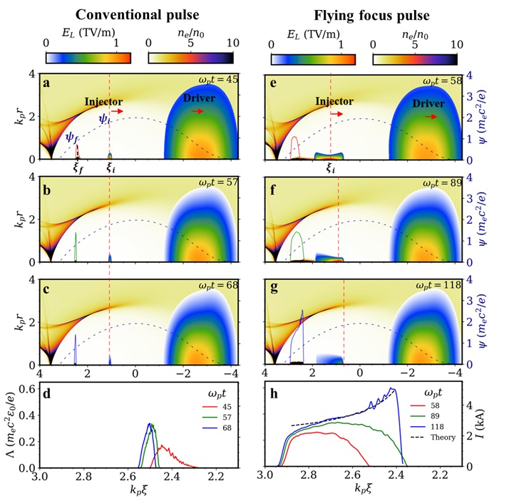
The electron bunch formed by the ionization, acceleration, and trapping depends on the dynamics of the injector. The peak intensity of a conventional pulse and location at which it ionizes move at approximately the group velocity . As a result, the location of ionization is nearly fixed in the moving frame coordinate [red dashed line in Figs. 2(a-c)], which provides almost no flexibility to structure the injected bunch. In contrast, the peak intensity of the flying focus injector travels at a specified velocity , producing an ionization front that moves in [red dashed line in Figs. 2(e-g)]. The ability to control the velocity of the moving ionization front provides the flexibility needed to structure the longitudinal profile of the injected bunch.
The flying focus pulse required for such an ionization front can be produced using recently developed techniques for spatiotemporal control of laser pulses. While several methods have been demonstrated and proposed [12, 13, 14, 15, 16, 17, 18], all share the property that the focal point, and thus the peak intensity, can be made to move at a velocity that is decoupled from the group velocity over a distance that is much longer than the Rayleigh length. Crucially, when , the motion of the peak intensity in the coordinate is accompanied by motion in the moving frame coordinate :
| (1) |
where normalized units have been adopted (see Methods). Thus, the flexibility to specify provides control over the motion of the peak intensity and ionization front in .
The motion of the ionization front determines the longitudinal profile of the injected bunch. The profile can be derived from the location of ionization using the normalized wake potential, , where and are the scalar and vector potentials of the plasma wave, respectively. The freed electrons will be trapped in the plasma wave if , where is the initial wake potential experienced by an electron when it is freed and is the minimum wake potential experienced [19, 20, 21]. Near the propagation axis (), , where depends on the strength of the plasma wave [11, 22, 23]. Thus, the trapping condition provides a direct connection between the location of ionization and the location of injection , where the electron reaches the same velocity as plasma wave: [points marked in Fig. 2(a)].
The charge per unit length of the injected bunch is given by
| (2) |
The first term on the right-hand-side is the charge per unit length of electrons freed by the injector pulse along its propagation path: , where is the spot size at the instant of ionization and is the background ion density. The second term describes the motion of the ionization point in the co-moving coordinate. The third term is a compression factor, which describes the spatial compression of the injected electrons as they are trapped. For a conventional injector pulse, the location of ionization moves only slightly due to diffraction and . As a result, the injected electrons coalesce into a narrowly peaked, triangular profile [Fig. 2(d)]. For a flying focus injector, [Eq. (1)], such that
| (3) |
which is nearly trapezoidal in [dashed line in Fig. 2(h)].
The formation of a charge per unit length with trapezoidal profile is critical for achieving a low energy spread in a subsequent plasma or laser wakefield acceleration stage. Such a profile flattens the longitudinal electric field in the region occupied by the bunch [22] so that all of the electrons gain approximately the same energy. The flying focus injector produces a near-ideal trapezoidal bunch with 220 pC of charge and transverse emittances of nm-rad and nm-rad. These values meet the collider requirements laid out in the Snowmass parameter set [5]. The conventional injector pulse, on the other hand, results in a triangularly shaped bunch with 17 pC of charge and a normalized emittance of 140 nm [Fig. 2(d)]. This triangular profile would be ineffective in flattening the longitudinal field, leading to a suboptimal energy spread in the acceleration stage. Moreover, while the emittance meets the requirements for collider applications, the charge is far too low. Thus, the triangular bunch is inadequate for collider applications.
The total injected charge is given by , where is the distance over which the injector pulses ionize. For a flying focus, this distance is the focal range , which is independent of the spot size and much greater than the Rayleigh range . For a conventional pulse, . Thus, with the same spot size, a flying focus can inject more charge than a conventional pulse by ionizing over a much longer distance (). While the charge injected by a conventional pulse can be increased by using a larger spot size (Rayleigh range), this has the detrimental effect of increasing the emittance. As an example, simulations (see Supplemental) indicate that a conventional pulse can achieve 236 pC of charge with a spot size of 15 m, but the resulting emittance m-rad and m-rad is too large to meet the Snowmass requirements.
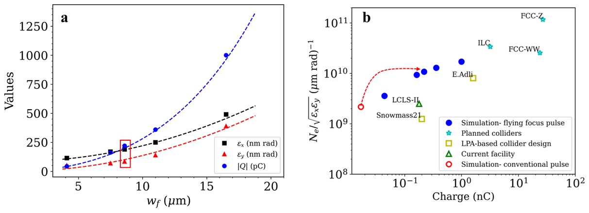
The properties of the injected electron bunch can be optimized by adjusting the parameters of the flying focus pulse. For instance, Fig. 3(a) shows that the charge can be scaled to over 1 nC by increasing the spot size of the flying focus. While the increase in charge comes at the cost of higher emittances, each of the simulated spot sizes (points) resulted in an electron bunch with a near-ideal trapezoidal profile (see Supplemental for the results of the 1 nC bunch). The simulation results are in excellent agreement with the theory (dashed lines) for the total charge and emittance (see Methods) [27, 10]. The agreement suggests that the flying focus photoinjector could produce electron bunches with charges exceeding 1 nC or emittances as low as 10 nm. This tunability can be used to generate electron beams with properties that are tailored to a particular application.
Figure 3(b) demonstrates that the flying focus photoinjector produces bunches with quality comparable to those of proposed conventional colliders and plasma-based colliders. In a collider, the beam quality is measured using the luminosity, i.e., the event rate per unit time per unit area, given by . Here, and are the number of particles in the colliding beams, is the collision frequency, is the particle energy, is the cross section of the beam, and is an geometry-dependent factor. The flying focus injector results in an electron contribution to the luminosity that satisfies the criteria for plasma-based colliders, as outlined by E. Adli et al. [24] and the Snowmass report [4] (blue circles compared to yellow squares). The red dashed arrow highlights the improved luminosity of the flying focus pulse over the conventional pulse for the case presented in Fig. 2.
| Parameter | Value | Units |
| Drive beam electron energy | 20 | GeV |
| Drive beam charge | 0.7 | nC |
| Drive beam dimensions , , | 10, 10, 20 | m |
| Injected bunch energy | 10 | MeV |
| Injected bunch charge | 220 | pC |
| Initial injected bunch emittances , | 171, 76 | nm rad |
| Background electron density | cm-3 |
For collider applications, the bunch produced by the flying focus photoinjector must be accelerated to high energy with a narrow energy spread. Achieving a narrow energy spread in a subsequent beam or laser-driven plasma acceleration stage requires placing the bunch in a region of the plasma wave where it can flatten, or “load,” the longitudinal electric field . This ensures that all electrons within the bunch experience the same longitudinal acceleration. The formalism for calculating the needed to flatten was developed in Ref. [22] for the case of a large plasma bubble , where is the bubble radius. In this formalism, the injected bunch flattens the field from an initially unloaded profile to a constant loaded field . However, the electron beams available at existing facilities typically drive slightly weaker plasma waves with an between one and three, such that with . In this more general case, the charge per unit length needed to flatten the longitudinal field is given by
| (4) |
This equation describes a trapezoid starting at , where the first term is the maximum value and in the second term is the slope. To ensure that the injected bunch flattens to a desired value of , the acceleration stage must be designed so that and produce an approximate equality between Eqs. (3) and (4).
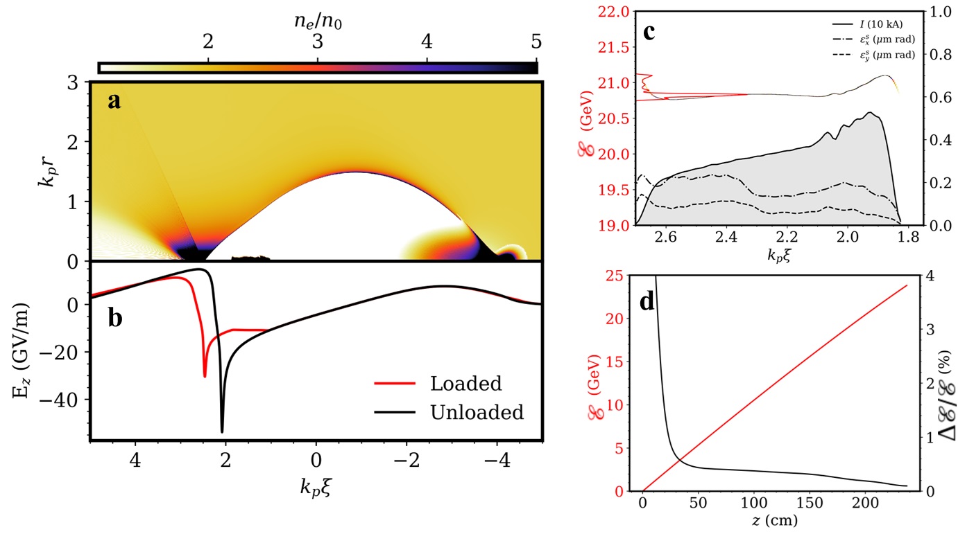
The electron beam-driven acceleration stage demonstrated here is designed to have a loaded field of approximately for the trapezoidal bunch with 220 pC of charge, nm-rad, and nm-rad [Fig. 2(e-h)]. The triangular bunch [Fig. 2(d)] is not considered because (1) it has a much lower charge and (2) its spatial profile does not flatten the accelerating field, which would lead to a higher energy spread. Both of these make the triangular bunch unsuitable for collider applications. To match the slope and maximum value of the trapezoidal profile, the plasma wave in the second stage must have [determined by the slope of in Fig. 2(h)], leading to as prescribed by Eq. (4). Given and an electron beam size , the charge of the drive beam can be found from the matched condition [28]. Using the loaded field of and , the background electron density can be written as . The density is selected to ensure that the length of the accelerating structure exceeds the length of the injected bunch. Here, the accelerating structure is set to three times the bunch length, resulting in a background electron density of . These and the remaining parameters for the simulations of the acceleration stage are provided in Table 2.
As shown in Figs. 4(a,b), the electron beam drives a nonlinear plasma wave with a longitudinal field that is flattened by the trailing bunch. The trapezoidal profile of the bunch and flattened field are preserved over the entire 2 m length of the accelerator [Fig. 4(c)]. The electron bunch reaches an average energy of 21 GeV with a spread of well less than 1% [Fig. 4(d)]. The final slice emittances are nearly uniform across the bunch, and the average emittances, nm-rad and nm-rad, are only slightly larger than their initial values. The accelerator efficiency, i.e., the ratio of energy gained by the bunch to the energy lost by the drive beam, is 43%. The 21 GeV average energy of the bunch compares favorably to the 28 GeV maximum that could be obtained from the drive beam. These results demonstrate that the flying focus photoinjector can provide the bunch needed for an intermediate energy collider as defined by the Snowmass parameter set [5].
The laser system suggested for the plasma photoinjector introduced in this paper is consistent with the near-term upgrades planned for the Accelerator Test Facility (ATF) at Brookhaven National Laboratory. Currently, ATF is the only facility worldwide operating a long-wave infrared laser system capable of generating multi-terawatt peak power in clean picosecond pulses. The laser currently produces 2 ps pulses with up to 5 TW of peak power. An active R&D effort is underway to increase the power to TW while reducing the pulse duration to fs. This will be achieved by upgrading the laser seed in the front end and through novel methods for temporal compression, such as self-phase modulation in a nonlinear medium. This particular method was recently used to generate a CO2 pulse as short as 675 fs [29], demonstrating a key technology for achieving sub-ps CO2 pulses.
A novel plasma photoinjector that leverages the dynamic focal point of a flying focus pulse can produce electron bunches with the charge, emittance, and luminosity required for collider applications. The moving ionization front driven by the flying focus allows for the injection and formation of an electron bunch with a trapezoidal profile that is nearly ideal for flattening the longitudinal field of a nonlinear plasma wave. In simulation that demonstrated the creation of such a bunch and its subsequent acceleration in an electron beam-driven plasma wave, the bunch achieved a final energy spread of less than 1% while extracting energy from the driver at efficiency. The simulated parameters were targeted towards a mid-scale 20 GeV electron beam based on the requirements of recent Snowmass studies. By adjusting the spot size of the flying focus, the injected trapezoidal bunch can be tailored to have nC of charge or nm of emittance. This is the first application of spatiotemporal pulse shaping to the creation of structured electron bunches for plasma-based acceleration. Beyond collider applications, the high-quality bunches produced by the flying focus photoinjector also satisfy many of the requirements for advanced radiation sources, such as free-electron lasers.
Methods
Injection stage simulations: The simulations of the injection stage were performed using the particle-in-cell (PIC) code OSIRIS [30], which solves the fully relativistic equations of motion for particles and employs a finite-difference time-domain solver for the electromagnetic fields. The simulations were discretized in the quasi-3D geometry, which represents quantities as a truncated expansion in azimuthal modes [31]. For systems with a high degree of cylindrical symmetry, this significantly reduces the computational resources required, while retaining important 3D effects. The customized solver introduced in Ref. [32] was used to ensure accurate dispersion of the electromagnetic waves (e.g., the injector and drive pulses).
The simulations used a moving window propagating at the vacuum speed of light with a size of 400 m 225 m ( cells) in and , respectively. Two azimuthal modes () were sufficient to model the laser pulse and plasma geometry. The initial particle arrangement in each cell was (2,2,8) for a total of 32 particles per cell.
The initial plasma was preionized Kr8+, and the injector pulses further ionized the plasma from Kr8+ to Kr9+. The ionization rates were calculated using the ADK ionization model [33]. The treshold values of for some of the relevant ionization states are displayed in Table 3. The of the CO2 laser pulse was chosen to be between the thresholds of the and the ionization states.
Acceleration stage simulations: For the acceleration stage, the injected electron bunches resulting from OSIRIS were imported into QPAD. QPAD is a quasi-static PIC code that employs azimuthal decomposition [34]. QPAD was used for the acceleration stage because running OSIRIS for a 2 m long plasma would be computationally expensive and yield nearly identical results. The simulations used a moving window propagating at the vacuum speed of light with a size of 261 m 95 m ( cells) in and , respectively. A single azimuthal mode () was sufficient for the electron beam, injected bunch, and plasma configuration. The equations of motion for the relativistic electron beam and bunch were evolved with a time step of fs.
Normalized units: Unless units are explicitly written or otherwise stated, time and length are normalized to and , respectively, velocity to the vacuum speed of light , density to the electron density , charge to the fundamental charge , potentials to , linear charge density to , and fields to . Here, is the plasma frequency and is the electron mass. Note that is different in the injection and acceleration stages.
| Ionization levels of Kr | ( m ) | ( m ) |
|---|---|---|
| Kr Kr8+ | 1.87 | 0.06 |
| Kr Kr9+ | 3.10 | 0.16 |
| Kr Kr10+ | 3.78 | 0.20 |
| Kr Kr11+ | 4.51 | 0.23 |
Modeling flying focus laser pulse in PIC simulations: The framework of arbitrarily structured laser (ASTRL) pulses [35] was used to initialize the flying focus pulse in the injection stage simulations. The transverse electric field of the pulse was initialized as a carrier wave modulating an envelope: , where is the carrier wavenumber, is the polarization vector, and is the envelope. A vacuum paraxial solution was used for the envelope:
| (5) |
where is the normalized vector potential, quantifies the amount of chirp, is the local frequency, is Rayleigh range, is the focused spot size, is the complex beam parameter, and is the -dependent focal length. Equation 5 captures the essential features of a chromatic flying focus [12, 13], including the extended focal region, controllable velocity, and chirp. The intensity peak of the pulse can be programmed to move at a constant velocity in vacuum by choosing . This produces an extended focal region of length , where is the duration of the pulse set by . The full-width-at-half-maximum duration of the moving intensity peak within the focal region is . Note that Eqn. 5 is an ASTRL pulse because it is the result of evaluating Eqn. 7 in Ref. [35] when is a Dirac delta function and is a Gaussian beam. A special case of this form was used to model a flying focus in Ref. [36].
Transverse emittances: According to Refs. [10, 23, 37], ionization injection with a laser pulse polarized in the -direction results in the saturated transverse emittances
| (6) |
where
| (7) |
is the threshold amplitude for fully ionizing Kr Kr9+, eV is the ionization potential for Kr Kr9+, eV, is the classical electron radius, and is the fine structure constant.
Supplementary information
Acknowledgements We acknowledge the support by the U.S. Department of Energy, Office of Science under Award No. DE-SC-0014043, DE-SC-0020396, NSF CAREER Award PHY-2238840, resources of NERSC facility, operated under contract No. DE-AC02-5CH11231, and SEAWULF at Stony Brook University. The work of J.P.P. and T.T.S. was supported by the Office of Fusion Energy Sciences under Award Number DE-SC0021057.
References
- \bibcommenthead
- Mangles et al. [2004] Mangles, S.P.D., Murphy, C.D., Najmudin, Z., Thomas, A.G.R., Collier, J.L., Dangor, A.E., Divall, E.J., Foster, P.S., Gallacher, J.G., Hooker, C.J., Jaroszynski, D.A., Langley, A.J., Mori, W.B., Norreys, P.A., Tsung, F.S., Viskup, R., Walton, B.R., Krushelnick, K.: Monoenergetic beams of relativistic electrons from intense laser–plasma interactions. Nature 431, 535–538 (2004)
- Geddes et al. [2004] Geddes, C.G.R., Toth, C., Tilborg, J., Esarey, E., Schroeder, C.B., Bruhwiler, D., Nieter, C., Cary, J., Leemans, W.P.: High-quality electron beams from a laser wakefield accelerator using plasma-channel guiding. Nature 431, 538–541 (2004)
- Faure et al. [2004] Faure, J., Glinec, Y., Pukhov, A., Kiselev, S., Gordienko, S., Lefebvre, E., Rousseau, J.-P., Burgy, F., Malka, V.: A laser–plasma accelerator producing monoenergetic electron beams. Nature 431, 541–544 (2004)
- Schroeder et al. [2023] Schroeder, C.B., Albert, F., Benedetti, C., Bromage, J., Bruhwiler, D., Bulanov, S.S., Campbell, E.M., Cook, N.M., Cros, B., Downer, M.C., Esarey, E., Froula, D.H., Fuchs, M., Geddes, C.G.R., Gessner, S.J., Gonsalves, A.J., Hogan, M.J., Hooker, S.M., Huebl, A., Jing, C., Joshi, C., Krushelnick, K., Leemans, W.P., Lehe, R., Maier, A.R., Milchberg, H.M., Mori, W.B., Nakamura, K., Osterhoff, J., Palastro, J.P., Palmer, M., Põder, K., Power, J.G., Shadwick, B.A., Terzani, D., Thévenet, M., Thomas, A.G.R., Tilborg, J., Turner, M., Vafaei-Najafabadi, N., Vay, J.-L., Zhou, T., Zuegel, J.: Linear colliders based on laser-plasma accelerators. Journal of Instrumentation 18(06), 06001 (2023)
- Bulanov et al. [2024] Bulanov, S., Aidala, C., Benedetti, C., Bernstein, R., Esarey, E., Geddes, C., Gessner, S., Gonsalves, A., Hogan, M., Jacobs, P., et al.: The science case for an intermediate energy advanced and novel accelerator linear collider facility. Journal of Instrumentation 19(01), 01010 (2024)
- Faure [2017] Faure, J.: Plasma injection schemes for laser-plasma accelerators. Technical report, CERN (2017)
- Fuchs et al. [2024] Fuchs, M., Andonian, G., Apsimon, O., Büscher, M., Downer, M., Filippetto, D., Lehrach, A., Schroeder, C., Shadwick, B., Thomas, A., et al.: Plasma-based particle sources. Journal of Instrumentation 19(01), 01004 (2024)
- Xu et al. [2014] Xu, X., Wu, Y., Zhang, C., Li, F., Wan, Y., Hua, J., Pai, C.-H., Lu, W., Yu, P., Joshi, C., et al.: Low emittance electron beam generation from a laser wakefield accelerator using two laser pulses with different wavelengths. Physical Review Special Topics-Accelerators and Beams 17(6), 061301 (2014)
- Yu et al. [2014] Yu, L.-L., Esarey, E., Schroeder, C.B., Vay, J.-L., Benedetti, C., Geddes, C.G.R., Chen, M., Leemans, W.P.: Two-color laser-ionization injection. Phys. Rev. Lett. 112, 125001 (2014)
- Schroeder et al. [2015] Schroeder, C., Benedetti, C., Bulanov, S., Chen, M., Esarey, E., Geddes, C.C., Vay, J.-L., Yu, L., Leemans, W.: Ultra-low emittance beam generation using two-color ionization injection in laser-plasma accelerators. In: Laser Acceleration of Electrons, Protons, and Ions III; and Medical Applications of Laser-Generated Beams of Particles III, vol. 9514, pp. 8–14 (2015). SPIE
- Lu et al. [2006] Lu, W., Huang, C., Zhou, M., Mori, W.B., Katsouleas, T.: Nonlinear theory for relativistic plasma wakefields in the blowout regime. Physical Review Letters 96(16), 165002 (2006)
- Froula et al. [2018] Froula, D.H., Turnbull, D., Davies, A.S., Kessler, T.J., Haberberger, D., Palastro, J.P., Bahk, S.-W., Begishev, I.A., Boni, R., Bucht, S., et al.: Spatiotemporal control of laser intensity. Nature Photonics 12(5), 262–265 (2018)
- Palastro et al. [2018] Palastro, J.P., Turnbull, D., Bahk, S.-W., Follett, R.K., Shaw, J.L., Haberberger, D., Bromage, J., Froula, D.H.: Ionization waves of arbitrary velocity driven by a flying focus. Phys. Rev. A 97, 033835 (2018)
- Palastro et al. [2020] Palastro, J.P., Shaw, J.L., Franke, P., Ramsey, D., Simpson, T.T., Froula, D.H.: Dephasingless laser wakefield acceleration. Phys. Rev. Lett. 124, 134802 (2020)
- Turnbull et al. [2018] Turnbull, D., Franke, P., Katz, J., Palastro, J., Begishev, I., Boni, R., Bromage, J., Milder, A., Shaw, J., Froula, D.: Ionization waves of arbitrary velocity. Physical Review Letters 120(22), 225001 (2018)
- Palastro et al. [2021] Palastro, J., Malaca, B., Vieira, J., Ramsey, D., Simpson, T., Franke, P., Shaw, J., Froula, D.: Laser-plasma acceleration beyond wave breaking. Physics of Plasmas 28(1) (2021)
- Miller et al. [2023] Miller, K.G., Pierce, J.R., Ambat, M.V., Shaw, J.L., Weichman, K., Mori, W.B., Froula, D.H., Palastro, J.P.: Dephasingless laser wakefield acceleration in the bubble regime. Scientific Reports 13(1), 21306 (2023)
- Pigeon et al. [2024] Pigeon, J., Franke, P., Chong, M.L.P., Katz, J., Boni, R., Dorrer, C., Palastro, J., Froula, D.: Ultrabroadband flying-focus using an axiparabola-echelon pair. Optics Express 32(1), 576–585 (2024)
- Oz et al. [2007] Oz, E., Deng, S., Katsouleas, T., Muggli, P., Barnes, C., Blumenfeld, I., Decker, F., Emma, P., Hogan, M., Ischebeck, R., et al.: Ionization-induced electron trapping in ultrarelativistic plasma wakes. Physical Review Letters 98(8), 084801 (2007)
- Pak et al. [2010] Pak, A., Marsh, K., Martins, S., Lu, W., Mori, W., Joshi, C.: Injection and trapping of tunnel-ionized electrons into laser-produced wakes. Physical Review Letters 104(2), 025003 (2010)
- McGuffey et al. [2010] McGuffey, C., Thomas, A., Schumaker, W., Matsuoka, T., Chvykov, V., Dollar, F., Kalintchenko, G., Yanovsky, V., Maksimchuk, A., Krushelnick, K., et al.: Ionization induced trapping in a laser wakefield accelerator. Physical Review Letters 104(2), 025004 (2010)
- Tzoufras et al. [2008] Tzoufras, M., Lu, W., Tsung, F.S., Huang, C., Mori, W.B., Katsouleas, T., Vieira, J., Fonseca, R.A., Silva, L.O.: Beam loading in the nonlinear regime of plasma-based acceleration. Phys. Rev. Lett. 101, 145002 (2008)
- Xu et al. [2014] Xu, X.L., Hua, J.F., Li, F., Zhang, C.J., Yan, L.X., Du, Y.C., Huang, W.H., Chen, H.B., Tang, C.X., Lu, W., Yu, P., An, W., Joshi, C., Mori, W.B.: Phase-space dynamics of ionization injection in plasma-based accelerators. Phys. Rev. Lett. 112, 035003 (2014)
- Delahaye et al. [2014] Delahaye, J.-P., Adli, E., Gessner, S., Hogan, M., Raubenheimer, T., An, W., Joshi, C., Mori, W.: A beam driven plasma-wakefield linear collider from higgs factory to multi-tev. In: Proceedings of the 5th International Particle Accelerator Conference (IPAC’14), pp. 3791–3793 (2014)
- Abada et al. [2019] Abada, A., Abbrescia, M., AbdusSalam, S., Abdyukhanov, I., Abelleira Fernandez, J., Abramov, A., Aburaia, M., Acar, A., Adzic, P., Agrawal, P., et al.: Fcc-ee: The lepton collider: Future circular collider conceptual design report volume 2. The European Physical Journal Special Topics 228, 261–623 (2019)
- Raubenheimer et al. [2018] Raubenheimer, T., et al.: The lcls-ii-he, a high energy upgrade of the lcls-ii. In: 60th ICFA Advanced Beam Dynamics Workshop on Future Light Sources, pp. 6–11 (2018)
- Schroeder et al. [2014] Schroeder, C., Vay, J.-L., Esarey, E., Bulanov, S., Benedetti, C., Yu, L.-L., Chen, M., Geddes, C., Leemans, W.: Thermal emittance from ionization-induced trapping in plasma accelerators. Physical Review Special Topics-Accelerators and Beams 17(10), 101301 (2014)
- Tzoufras et al. [2009] Tzoufras, M., Lu, W., Tsung, F.S., Huang, C., Mori, W.B., Katsouleas, T., Vieira, J., Fonseca, R., Silva, L.: Beam loading by electrons in nonlinear plasma wakes. Physics of Plasmas 16(5) (2009)
- Pogorelsky et al. [2024] Pogorelsky, I.V., Polyanskiy, M.N., Babzien, M., Simmonds, A., Palmer, M.A.: Terawatt-class femtosecond long-wave infrared laser. Frontiers in Physics 12, 1390225 (2024)
- Fonseca et al. [2002] Fonseca, R.A., Silva, L.O., Tsung, F.S., Decyk, V.K., Lu, W., Ren, C., Mori, W.B., Deng, S., Lee, S., Katsouleas, T., Adam, J.C.: Osiris: A three-dimensional, fully relativistic particle in cell code for modeling plasma based accelerators. In: Computational Science — ICCS 2002, pp. 342–351. Springer, Berlin, Heidelberg (2002)
- Davidson et al. [2015] Davidson, A., Tableman, A., An, W., Tsung, F.S., Lu, W., Vieira, J., Fonseca, R.A., Silva, L.O., Mori, W.B.: Implementation of a hybrid particle code with a PIC description in r–z and a gridless description in into OSIRIS. Journal of Computational Physics 281, 1063–1077 (2015)
- Li et al. [2021] Li, F., Miller, K.G., Xu, X., Tsung, F.S., Decyk, V.K., An, W., Fonseca, R.A., Mori, W.B.: A new field solver for modeling of relativistic particle-laser interactions using the particle-in-cell algorithm. Computer Physics Communications 258, 107580 (2021)
- Bruhwiler et al. [2003] Bruhwiler, D.L., Dimitrov, D., Cary, J.R., Esarey, E., Leemans, W., Giacone, R.E.: Particle-in-cell simulations of tunneling ionization effects in plasma-based accelerators. Physics of Plasmas 10(5), 2022–2030 (2003)
- Li et al. [2021] Li, F., An, W., Decyk, V.K., Xu, X., Hogan, M.J., Mori, W.B.: A quasi-static particle-in-cell algorithm based on an azimuthal fourier decomposition for highly efficient simulations of plasma-based acceleration: Qpad. Computer Physics Communications 261, 107784 (2021)
- Pierce et al. [2023] Pierce, J.R., Palastro, J.P., Li, F., Malaca, B., Ramsey, D., Vieira, J., Weichman, K., Mori, W.B.: Arbitrarily structured laser pulses. Physical Review Research 5(1), 013085 (2023)
- Franke et al. [2021] Franke, P., Ramsey, D., Simpson, T.T., Turnbull, D., Froula, D., Palastro, J.: Optical shock-enhanced self-photon acceleration. Physical Review A 104(4), 043520 (2021)
- Xu [2020] Xu, X.: Phase Space Dynamics in Plasma Based Wakefield Acceleration. Springer Theses. Springer, Singapore (2020)