Ratchet motion of magnetic skyrmions driven by surface acoustic sawtooth waves
Abstract
The manipulation of skyrmions by surface acoustic waves (SAW) has garnered significant interest in the field of spintronic devices. Previous studies established that skyrmions can be generated and moved by strain pulses. In this study, we propose that sawtooth-SAWs can be used to drive a ratchet motion of magnetic skyrmions in the presence of pinning centers. This results in a net motion of the skyrmions orthogonal to the continuously applied SAW. The ratchet motion is fundamentally caused by non-vanishing pinning, so that a certain strain gradient magnitude is required to overcome pinning and start skyrmion motion. We demonstrate the feasibility of our concept by micromagnetic simulations and analytical model calculations.
I Introduction
In the last decade, magnetic skyrmions have emerged as a subject of interest in the field of modern computing, particularly in the context of their potential application for data storage [1, 2, 3, 4, 5], reservoir and neuromorphic computing [6, 7, 8, 9, 10, 11]. To leverage skyrmions for these applications, it is imperative to generate and annihilate skymrions and also control their position. Such skyrmion transport can be achieved by employing spin-transfer or spin-orbit torques caused by electric currents [12, 13, 14], which is the most widespread concept, but comes with drawbacks such as Joule heating and material constraints due to requiring conductive materials, and / or large spin-orbit interactions. An alternative approach to manipulating skyrmions without Joule heating involves strain in the magnetic film. The application of strain by, e.g., surface acoustic waves (SAWs), enables the creation of skyrmions [15, 16] and their manipulation through strain gradients [17, 18, 19, 20]. Similar to magnetic skyrmions, the polarization of the magnetic vortex is topologically stabilized and has also already been proven to be driven by SAWs [21, 22, 23, 24]. The use of SAWs is thereby desirable due to the maturity of the SAW technology and planar transducer design. Throughout numerous studies of electrically or elastically driven skyrmion motion, the fundamental importance of pinning has been widely recognized. Additionally, research has been conducted on the impact of pinning on different types of skyrmions and by different size of a disk-shaped defect [25] as well as on the pinning energy landscape in a real sample [26]. While pinning might seem detrimental to skyrmion motion as it increases the threshold current / strain gradient for onset of skymrion motion, researchers have also realized that pinning can be exploited to realize deterministic skyrmion motion. For instance, the utilization of pinning centers for the creation of a guided track and the subsequent manipulation of these tracks through electrical currents have been demonstrated [27]. Here we show that skyrmion pinning can be exploited to cause unidirectional motion of skyrmions with appropriately engineered and continuously applied SAWs. While sinusoidal SAWs would result in oscillatory motion of either pinned or unpinned skyrmions, we show that a sawtooth SAW profile can be used to generate a ratchet-like skyrmion motion, resulting in net skyrmion transport from pinning center to pinning center in a direction roughly perpendicular to the SAW propagation direction.
II Concept
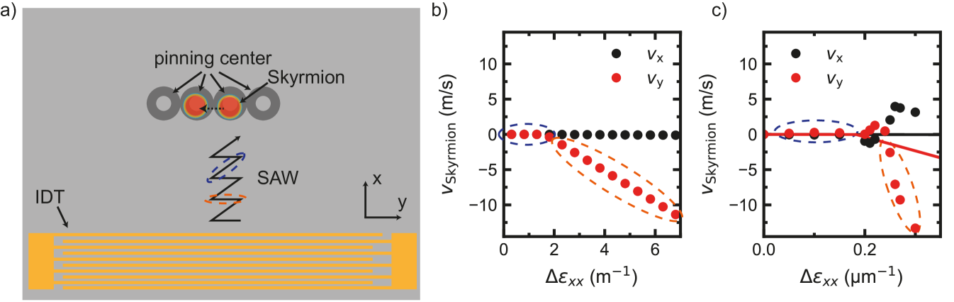
Fig.1 a) depicts the proposed device. The device consists of an interdigital transducer (IDT) that launches a sawtooth-shaped SAW towards an (arbitrary) pinning landscape, where a single skyrmion is pinned to an (initially random) pinning center. The creation of such surface acoustic waves can be experimentally implemented by the Fourier synthesis of multiple sinusoidal signals as demonstrated in [28, 29]. The skyrmion can be generated by nucleation at a constriction [30], ion radiation [31, 32, 33] by a strain pulse [15, 16] or electrical currents [34, 35, 36, 37, 38, 39]. As detailed in the following, the skyrmion can be depinned from the pinning center by a sufficiently large strain gradient, while it will remain pinned for small strain gradients. We now propose to design the sawtooth profile in such a way that its rising slope (red ellipses in Fig.1 a)) results in a strain gradient that is sufficiently large to depin the skyrmion, while the falling slope (blue ellipses) is sufficiently small such that the force exerted on the skyrmion by the strain gradient stays below the depinning threshold. A periodic and continuously applied sawtooth SAW then depins the skyrmion and moves it from pinning center to pinning center in a unidirectional motion. In the following we discuss the feasibility of this concept by means of analytical calculations and micromagnetic simulations.
III Analytical Model
We start by performing an analytical calculation of the strain gradient necessary to depin a µm-sized skyrmion from a pinning center. The magnetization of the Néel-type skyrmion in the anlytical model is described by
| (1) | ||||
Here describes the skyrmion radius and and are the polar coordinates in relation to the Cartesian coordinate system of Fig. 1 a). With these magnetization components, the magnetoelastic free energy density contribution for a polycrystalline magnet (magnetoelastic constant ) can be written as [40]
| (2) |
In our analytical model, we assume that the skyrmion shape is rigid, viz. it does not change under the application of strain gradients. This assumption is supported by the subsequent micromagnetic simulations (see below). Moreover, we assume a uniform and linear strain gradient over the skyrmion diameter, such as obtained by a perfect sawtooth-SAW with wavelength much larger than the skyrmion diameter. In this case, we obtain the spatial dependence of the strains as , where denotes the center of the skyrmion. By inserting this definition and Eq. (1) into Eq. (2), the spatially averaged magnetoelastic contribution to the free energy density of a skyrmion within a linear strain gradient is obtained as
| (3) | ||||
with the skyrmion disk area . Multiplying this by the volume of the skyrmion we obtain the free energy for a single skyrmion
| (4) |
with the film thickness . We calculate the force acting on a skyrmion resulting from a strain gradient by differentiation of free energy with respect to the center position of the skyrmion .
| (5) |
Each circular pinning potential can be defined as [41]
| (6) |
with the radius of the pinning center and the pinning energy . Here denotes an effective pinning field. From this the maximum pinning force can be expressed as
| (7) |
The skyrmion velocity in dependence on the applied strain can be calculated by [18]
| (8) | |||
| (9) |
with , being the skyrmion winding number, and the gilbert damping. The resulting calculated skyrmion velocity at the location of maximum pinning in dependence of an applied strain gradient for , , , , and is shown in Fig. 1 b). The value of is chosen to have a similar pinning force as in the subsequent micromagnetic simulations (see below). At low strain gradients (blue dashed ellipse) the skyrmions velocity stays at 0, meaning that the skyrmion is pinned on the pinning center and can not move away form it. At higher applied strain gradients (orange dashed ellipse) the velocity in y-direction increases while the velocity in x-direction stays nearly constant at 0. We assume a purely longitudinal strain wave () as a simple approximation. To overcome the pinning, needs to be larger than and the minimal strain needed to depin the skyrmion is given by
| (10) |
With the parameters stated above, the strain needed to depin a skyrmion is . Dividing this by we get the required strain gradient . A comparison of the strain required to depin a skyrmion with experimentally accessible strains generated by surface acoustic waves (SAWs) reveals that the application of the latter is indeed feasible [42, 43]. Furthermore, the pinning energy and, therefore, the required strain could be further reduced by periodic field excitations [44].
IV Micromagnetic Simulation
To verify that the analytical calculations resemble the expected behaviour of a skyrmion, and to demonstrate that the concept can be transferred also to nanoscale skyrmions, micromagnetic simulations on nm-sized skyrmions are performed using mumax [45] within the Aithericon framework [46]. We use a cell size of and a grid size of with periodic boundary conditions. The CoFeB sample parameters for the simulation were taken from R. Gruber et. al [26]. The saturation magnetization is set to , the exchange stiffness as , and the Gilbert damping as . The anisotropy is set to . The magnetoelastic coupling is and the interfacial Dzyaloshinskii-Moriya interaction strength .
A Neel-type skyrmion is initialized in the center of the simulation region. A magnetic field of in the out-of plane direction is applied to stabilize the skyrmion. The resulting skyrmion has a size of approximately nm. At the region where the skyrmion is initialized, the anisotropy is reduced by 2% in a donut-shaped form to create a pinning center by reducing the energy of the skyrmion domain wall in this region. The strain gradients are then systematically varied to ascertain the strain required to depin the skyrmion. In Fig. 1 c), the velocity of the skyrmion in the x and y directions is plotted against a constant strain gradient in the x direction, with the skyrmion located within the center of the pinning together with the analytically calculated velocity indicated by the red () and black () lines. In qualitative agreement with the analytically calculated velocities (compare Fig. 1 b)) and the red and blue lines in Fig. 1 c), the velocity stays aproximately 0 for low applied strain gradients (blue dashed ellipse) and the skyrmion is depinned and can move freely at a sufficiently large applied strain gradient (orange dashed elipse).
The discrepancy in the skyrmion velocity of the depinned skyrmion in the micromagentic simulations compared to the analytically calculated velocity can be explained by the fact that in the micromagnetic simulations the skyrmion can move away from the pinning site, while in the analytical model the velocity is always calculated at the location of maximum pinning. Thus, it is evident from this figure that the strain gradient must surpass a threshold to facilitate skyrmion depinning from the region of reduced anisotropy. Subsequent to depinning, the skyrmion velocity increases to a value equivalent to that observed in the absence of a pinning center. It additionally shows that the skyrmion does not move fully perpendicular to the applied strain but at an angle due to the skyrmion Hall effect [47, 48, 49, 50, 51, 52, 53].
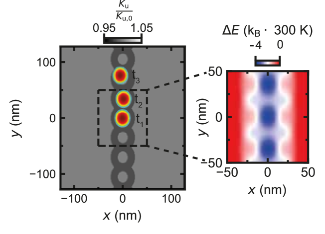
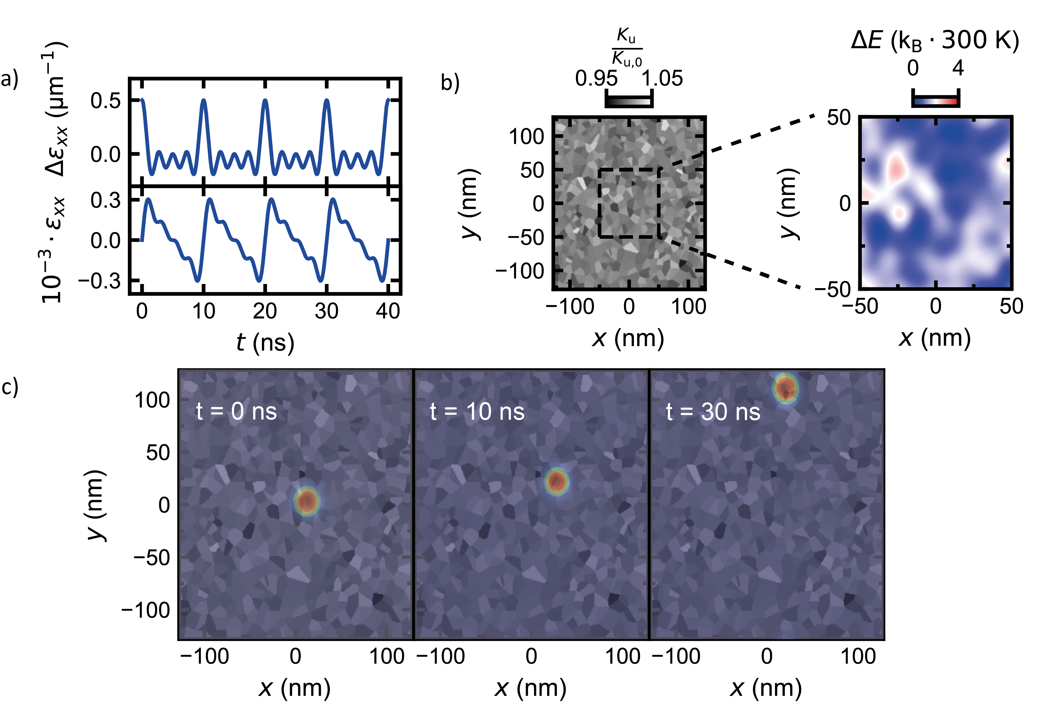
In order to ascertain the feasibility of relocating a skyrmion from one pinning site to another via an applied strain gradient, the single-pinning center is replicated to create a pinning chain. The resulting pinning chain, in conjunction with the energy landscape, is shown in Fig. 2. The anisotropy is reduced by 2% in a donut-shaped manner to form each pinning center. The right side of Fig. 2 presents the energy landscape resulting from the anisotropy region. The configuration with the lowest energy is that in which the skyrmion domain wall region matches the region of reduced anisotropy. Given that the minimum engergy regions are along the chain at the pinning centers, the skyrmion is inclined to move along the chain direction when applying a strain in the x-direction as the gradient needed to move it perpendicular to the chain would be higher. When a sufficiently high strain gradient is applied in the x-direction, the skyrmion can be depinned and move towards the next pinning center. This is depicted in Fig. 2 by the skyrmion at times and after nucleating it in the center at and applying a sawtooth-shaped SAW. In the case of applying the strain gradient in the opposite direction, the skyrmion also depins and moves in the opposite direction towards the next pinning center. Thus, if an sinusoidal surface acoustic wave is applied, the skyrmion would end up at the starting position due to the symmetric strain profile. This can be overcome by utilization of a sawtooth-shaped surface acoustic wave for the movement of the skyrmion. The creation of such a sawtooth-shaped SAW on a sample can be achieved through Fourier synthesis and the utilization of split-52 IDTs [28, 29]. The resulting strain and strain gradient from the sawtooth SAW, created by a Fourier synthesis of 4 sine waves, is shown in Fig. 3 a). In this configuration, the maximum strain gradient in the positive and negative directions is distinct. Consequently, the depinning of skyrmions is possible during the rising slope of the sawtooth SAW where the strain gradient is strong. On the falling slope of each SAW cycle, the skyrmions stay pinned.
Given that a chain of donut-shaped pinning centers does not accurately represent the actual pinning sites in a real sample, we implemented a more realistic pinning landscape. To this end, a randomized region with a grain size of 10 nm was utilized. The anisotropy within the grains was randomly reduced between 0 and 1% of . The resulting anisotropy landscape is illustrated in Fig. 3 b). From the anisotropy landscape, we calculated the energy landscape resulting from the regions of reduced anisotropy. This is illustrated in Fig. 3 b) on the right, which presents the energy landscape for a region of in the center. It is evident from the figure that the energy landscape now exhibits no discernible trajectory that would predetermine the skyrmion path by geometry of the simulation setup. The employed energy landscape is in good quantitative agreement with the experimentally recored energy landscapes in R.Gruber et. al [26] and consequently, we believe that our artificial energy landscape is a reasonable model for pinning in real samples. In Fig. 3 c), a skyrmion is positioned at the center of the anisotropy landscape depicted in Fig.3 b) at a time designated as . Then, a sawtooth-SAW is applied to the simulation area. This is achieved by applying a time-dependent constant strain gradient over the simulation area, in accordance to the most likely experimental implementation, where the SAW wavelength is considerably larger than the simulated area. It should be noted that only . After an initial 10-nanosecond period and the first cycle of the sawtooth-SAW (refer to Fig. 3 a), the skyrmion undergoes a slight displacement in the positive x and y directions. After the skyrmion reaches the top boundary of the simulated area while the x-position stayed approximately constant. In the aforementioned time periods, the skyrmion demonstrates notable movement when a high strain is applied, while remaining relatively stationary under low strain conditions leading to a ratchet motion of the skyrmion under an applied sawtooth SAW.
In our simulation the strain applied on the sample is . To verify that the proposed experiment is feasible we compare the strain used in the experiment with the maximum achieveable strain before sample destruction. This is for many materials generally in the order of to and given by the relation between the Young’s modulus and yield strength [54]. Moreover, SAW amplitudes of about at a distance of from the IDT and with a wavelength of corresponding to a strain of have been reported [55]. Taking into account that the reported value was not measured directly at the IDT we believe that it is possible to recreate the ratchet-like motion shown on our simulation. Moreover, considering that the required strain to depin the skyrmion is inversely proportional to the skyrmion radius (compare Eq. (10)) a low strain amplitude in the range is according to the analytical calculation sufficient to depin µm sized skyrmions. Thus, the strain needed to depin the skyrmion significantly decreases when using larger skyrmions.
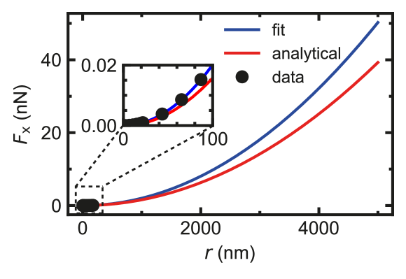
In order to verify that the analytical calculations and the micromagnetic simulations are compatible, the force from the strain gradient acting on the skyrmion in dependence of is simulated for , and . The micromagnetic simulation data are fitted with a parabola to capture the skymrion size dependence according to Eq. (5), and the resultant fit is then compared to the analytically calculated force. The results are presented in Fig. 4. The red curve corresponds to the force calculated using Eq. (5) and the blue curve represents the extrapolation of the parabolic fit of the force acting on a skyrmion obtained from micromagnetics. The inset illustrates the simulated data as black dots. The data show that the analytical calculation and the extrapolation of the simulation result in a comparable force acting on the skyrmion for a given applied strain gradient. However, it shows that the analytical calculations result in a slight underestimation of the force acting on the skyrmion. This might be due to the simplified magnetic texture and non deformable skyrmions in the analytical calculation. Due to the good agreement of micromagnetic and analytical model for nanoscale skyrmions we conclude that our analytical model can be utilized to estimate the strain gradient required to depin rigid skyrmions.
V Conclusion
In summary, we have shown by analytical model calculations as well as micromagnetic simulations, that sawtooth-shaped surface acoustic waves (SAWs) can be employed to move magnetic skyrmions in a ratchet-like motion from pinning center to pinning center. We estimate the strains required to move nanoscale or microscale skyrmions and find that the generation of the required strains should be experimentally feasible.
Acknowledgements.
VI Acknowldegements
We acknowledge financial support by the Deutsche Forschungsgemeinschaft (DFG, German Research Foundation)- Project No. 403505631, and by the European Union within the HORIZON-CL4-2021 under Grant No. 101044526 MAWiCS
References
- Suess et al. [2018] D. Suess, C. Vogler, F. Bruckner, P. Heistracher, and C. Abert, AIP Adv. 8, 115301 (2018).
- Müller [2017] J. Müller, New J. Phys. 19, 025002 (2017).
- Luo and You [2021] S. Luo and L. You, APL Mater. 9, 050901 (2021).
- Göbel and Mertig [2021] B. Göbel and I. Mertig, Sci. Rep. 11, 3020 (2021).
- Jiang et al. [2023] Y. Jiang, H. Yu, and X. Chen, J. Appl. Phys. 134, 053901 (2023).
- Song et al. [2020] K. M. Song, J.-S. Jeong, B. Pan, X. Zhang, J. Xia, S. Cha, T.-E. Park, K. Kim, S. Finizio, J. Raabe, J. Chang, Y. Zhou, W. Zhao, W. Kang, H. Ju, and S. Woo, Nat. Electron. 3, 148 (2020).
- Pinna et al. [2020] D. Pinna, G. Bourianoff, and K. Everschor-Sitte, Phys. Rev. Appl. 14, 054020 (2020).
- Raab et al. [2022] K. Raab, M. A. Brems, G. Beneke, T. Dohi, J. Rothörl, F. Kammerbauer, J. H. Mentink, and M. Kläui, Nat. Commun. 13, 6982 (2022).
- Lee and Mochizuki [2022] M.-K. Lee and M. Mochizuki, Phys. Rev. Appl. 18, 014074 (2022).
- Yokouchi et al. [2022] T. Yokouchi, S. Sugimoto, B. Rana, S. Seki, N. Ogawa, Y. Shiomi, S. Kasai, and Y. Otani, Sci. Adv. 8, eabq5652 (2022).
- Li et al. [2017] S. Li, W. Kang, Y. Huang, X. Zhang, Y. Zhou, and W. Zhao, Nanotechnology 28, 31LT01 (2017).
- Cai and Liu [2021] N. Cai and Y. Liu, J. Phys. D 54, 125001 (2021).
- Zhang et al. [2023] H. Zhang, Y. Zhang, Z. Hou, M. Qin, X. Gao, and J. Liu, Mater. Futures 2, 032201 (2023).
- Purnama et al. [2015] I. Purnama, W. L. Gan, D. W. Wong, and W. S. Lew, Sci. Rep. 5, 10620 (2015).
- Chen et al. [2023] R. Chen, C. Chen, L. Han, P. Liu, R. Su, W. Zhu, Y. Zhou, F. Pan, and C. Song, Nat. Commun. 14, 4427 (2023).
- Yokouchi et al. [2020] T. Yokouchi, S. Sugimoto, B. Rana, S. Seki, N. Ogawa, S. Kasai, and Y. Otani, Nat. Nanotechnol. 15, 361 (2020).
- Miyazaki et al. [2023] Y. Miyazaki, T. Yokouchi, and Y. Shiomi, Sci. Rep. 13, 1922 (2023).
- Liu et al. [2019] Y. Liu, X. Huo, S. Xuan, and H. Yan, J. Magn. Magn. Mater 492, 165659 (2019).
- Yang et al. [2024a] Y. Yang, L. Zhao, D. Yi, T. Xu, Y. Chai, C. Zhang, D. Jiang, Y. Ji, D. Hou, W. Jiang, J. Tang, P. Yu, H. Wu, and T. Nan, Nat. Commun. 15, 1018 (2024a).
- Shuai et al. [2024] J. Shuai, L. Lopez-Diaz, J. E. Cunningham, and T. A. Moore, Appl. Phys. Lett. 124, 202407 (2024).
- Koujok et al. [2023] A. Koujok, A. Riveros, D. R. Rodrigues, G. Finocchio, M. Weiler, A. Hamadeh, and P. Pirro, Appl. Phys. Lett. 123, 132403 (2023).
- Iurchuk et al. [2024] V. Iurchuk, J. Lindner, J. Fassbender, and A. Kákay, Phys. Rev. Lett. 133, 146701 (2024).
- Moukhader et al. [2024] R. Moukhader, D. R. Rodrigues, A. Riveros, A. Koujok, G. Finocchio, P. Pirro, and A. Hamadeh, J. Appl. Phys. 136, 183901 (2024).
- Seeger et al. [2024] R. L. Seeger, F. Millo, G. Soares, J.-V. Kim, A. Solignac, G. d. Loubens, and T. Devolder, arXiv 10.48550/arXiv.2409.05998 (2024).
- Gong et al. [2022] X. Gong, K. Y. Jing, J. Lu, and X. R. Wang, Phys. Rev. B 105, 094437 (2022).
- Gruber et al. [2022] R. Gruber, J. Zázvorka, M. A. Brems, D. R. Rodrigues, T. Dohi, N. Kerber, B. Seng, M. Vafaee, K. Everschor-Sitte, P. Virnau, and M. Kläui, Nat. Commun. 13, 3144 (2022).
- Stosic et al. [2017] D. Stosic, T. B. Ludermir, and M. V. Milošević, Phys. Rev. B 96, 214403 (2017).
- Schülein et al. [2015] F. J. R. Schülein, E. Zallo, P. Atkinson, O. G. Schmidt, R. Trotta, A. Rastelli, A. Wixforth, and H. J. Krenner, Nat. Nanotechnol. 10, 512 (2015).
- Weiß et al. [2018] M. Weiß, A. L. Hörner, E. Zallo, P. Atkinson, A. Rastelli, O. G. Schmidt, A. Wixforth, and H. J. Krenner, Phys. Rev. Appl 9, 014004 (2018).
- Wang et al. [2022] W. Wang, D. Song, W. Wei, P. Nan, S. Zhang, B. Ge, M. Tian, J. Zang, and H. Du, Nat. Commun. 13, 1593 (2022).
- De Jong et al. [2023] M. C. H. De Jong, B. H. M. Smit, M. J. Meijer, J. Lucassen, H. J. M. Swagten, B. Koopmans, and R. Lavrijsen, Phys. Rev. B 107, 094429 (2023).
- Fallon et al. [2020] K. Fallon, S. Hughes, K. Zeissler, W. Legrand, F. Ajejas, D. Maccariello, S. McFadzean, W. Smith, D. McGrouther, S. Collin, N. Reyren, V. Cros, C. H. Marrows, and S. McVitie, Small 16, 1907450 (2020).
- Zhao et al. [2023] Y. Zhao, J. Wang, L. Xu, P. Yu, M. Hou, F. Meng, S. Xie, Y. Meng, R. Zhu, Z. Hou, M. Yang, J. Luo, J. Wu, Y. Xu, X. Gao, C. Feng, and G. Yu, ACS Appl. Mate.r Interfaces 15, 15004 (2023).
- Yu et al. [2017] X. Yu, D. Morikawa, Y. Tokunaga, M. Kubota, T. Kurumaji, H. Oike, M. Nakamura, F. Kagawa, Y. Taguchi, T.-h. Arima, M. Kawasaki, and Y. Tokura, Adv. Mater. 29, 1606178 (2017).
- Akhtar et al. [2019] W. Akhtar, A. Hrabec, S. Chouaieb, A. Haykal, I. Gross, M. Belmeguenai, M. Gabor, B. Shields, P. Maletinsky, A. Thiaville, S. Rohart, and V. Jacques, Phys. Rev. Appl. 11, 034066 (2019).
- Mallick et al. [2022] S. Mallick, S. Panigrahy, G. Pradhan, and S. Rohart, Phys. Rev. Appl. 18, 064072 (2022).
- Quessab et al. [2022] Y. Quessab, J.-W. Xu, E. Cogulu, S. Finizio, J. Raabe, and A. D. Kent, Nano Lett. 22, 6091 (2022).
- Hrabec et al. [2017] A. Hrabec, J. Sampaio, M. Belmeguenai, I. Gross, R. Weil, S. M. Chérif, A. Stashkevich, V. Jacques, A. Thiaville, and S. Rohart, Nat. Commun. 8, 15765 (2017).
- Finizio et al. [2019] S. Finizio, K. Zeissler, S. Wintz, S. Mayr, T. Weßels, A. J. Huxtable, G. Burnell, C. H. Marrows, and J. Raabe, Nano Lett. 19, 7246 (2019).
- Dreher et al. [2012] L. Dreher, M. Weiler, M. Pernpeintner, H. Huebl, R. Gross, M. S. Brandt, and S. T. B. Goennenwein, Phys. Rev. B 86, 134415 (2012).
- Jiang et al. [2022] Y. Jiang, C. Xuan, and H. Yu, J. Magn. Magn. Mater 562, 169786 (2022).
- Weiler et al. [2011] M. Weiler, L. Dreher, C. Heeg, H. Huebl, R. Gross, M. S. Brandt, and S. T. B. Goennenwein, Phys. Rev. Lett. 106, 117601 (2011).
- Weiler et al. [2012] M. Weiler, H. Huebl, F. S. Goerg, F. D. Czeschka, R. Gross, and S. T. B. Goennenwein, Phys. Rev. Lett. 108, 176601 (2012).
- Gruber et al. [2023] R. Gruber, M. A. Brems, J. Rothörl, T. Sparmann, M. Schmitt, I. Kononenko, F. Kammerbauer, M.-A. Syskaki, O. Farago, P. Virnau, and M. Kläui, Adv. Mater 35, 2208922 (2023).
- Vansteenkiste et al. [2014] A. Vansteenkiste, J. Leliaert, M. Dvornik, M. Helsen, F. Garcia-Sanchez, and B. Van Waeyenberge, AIP Adv. 4, 107133 (2014).
- [46] See www.aithericon.com for Aithericon.
- Kim et al. [2018] K.-W. Kim, K.-W. Moon, N. Kerber, J. Nothhelfer, and K. Everschor-Sitte, Phys. Rev. B 97, 224427 (2018).
- Woo et al. [2018] S. Woo, K. M. Song, X. Zhang, Y. Zhou, M. Ezawa, X. Liu, S. Finizio, J. Raabe, N. J. Lee, S.-I. Kim, S.-Y. Park, Y. Kim, J.-Y. Kim, D. Lee, O. Lee, J. W. Choi, B.-C. Min, H. C. Koo, and J. Chang, Nat. Commun. 9, 959 (2018).
- Brearton et al. [2021] R. Brearton, L. A. Turnbull, J. a. T. Verezhak, G. Balakrishnan, P. D. Hatton, G. van der Laan, and T. Hesjedal, Nat. Commun. 12, 2723 (2021).
- Jiang et al. [2017] W. Jiang, X. Zhang, G. Yu, W. Zhang, X. Wang, M. Benjamin Jungfleisch, J. E. Pearson, X. Cheng, O. Heinonen, K. L. Wang, Y. Zhou, A. Hoffmann, and S. G. E. te Velthuis, Nat. Phys. 13, 162 (2017).
- Yang et al. [2024b] S. Yang, Y. Zhao, X. Zhang, X. Xing, H. Du, X. Li, M. Mochizuki, X. Xu, J. Åkerman, and Y. Zhou, Appl. Phys. Rev. 11, 041335 (2024b).
- Chen [2017] G. Chen, Nat. Phys. 13, 112 (2017).
- Litzius et al. [2017] K. Litzius, I. Lemesh, B. Krüger, P. Bassirian, L. Caretta, K. Richter, F. Büttner, K. Sato, O. A. Tretiakov, J. Förster, R. M. Reeve, M. Weigand, I. Bykova, H. Stoll, G. Schütz, G. S. D. Beach, and M. Kläui, Nat. Phys. 13, 170 (2017).
- Ashby [2011] M. F. Ashby, in Materials Selection in Mechanical Design (Fourth Edition), edited by M. F. Ashby (Butterworth-Heinemann, Oxford, 2011) pp. 57–96.
- Kavalerov et al. [2000] V. Kavalerov, T. Fujii, and M. Inoue, J. Appl. Phys. 87, 907 (2000).