Locating Rydberg Decay Error in SWAP-LRU
Abstract
Achieving fault-tolerant quantum computing with neutral atoms necessitates addressing inherent errors, particularly leakage from Rydberg states during the implementation of multi-qubit gates. Such leakage induces two-qubit error chains, which degrades the error distance and compromise the performance of error correction. While existing solutions, such as hardware-specific protocols (Erasure Conversion) and circuit-based protocols, have demonstrated favorable error distances ( for pure Rydberg decay) and high error thresholds, they rely on significant additional hardware resources. In this work, we propose a hardware-efficient approach to deal with Rydberg decay errors using SWAP-LRU, augmented by final leakage detection to locate errors. No additional resource is needed to remove leakage and renew atoms. When all leakage can be detected, we propose a located decoder and demonstrate a high error threshold of 2.33% per CNOT gate and demonstrate improved error distances for pure Rydberg decay, outperforming traditional Pauli error models. Furthermore, we introduce an alternative but more hardware-efficient solution, critical decoder. It only requires one type of leakage to be detected, yet effectively eliminates the damaging effects of Rydberg decay on sub-threshold scaling. Our findings provide new insights into located error and pave the way for a resource-efficient strategy to achieve fault-tolerant quantum computation with neutral atom arrays.
I Introduction
Neutral atom array has emerged as a promising platform for quantum computation [1, 2, 3, 4]. To design a protocol to realize error correction in neutral atoms platform, leakage error from Rydberg state needs specific consideration because it is an inherent and major error source for neutral atoms [5, 6, 7, 8, 9]. Without proper method to deal with, such leakage error degrades the error distance from to , greatly reducing the effectiveness of error correction [10, 11, 12, 9]. To address it, people has proposed different methods to handle it. Hardware-specific protocol is designed for alkaline-earth atoms, utilizing fast detection for unwanted transition to convert leakage error to benign erasure error after each multi-qubit gate [8, 13, 14, 15, 16, 17]. Demonstration on atoms is present [14]. Circuit-based protocol is to attach small-scale circuit to initial circuit, which detects the leakage error and renews the atoms at the same time [11, 6, 18]. Both theoretical protocols enhance the performance of error correction, achieving a high threshold and an error distance , for pure Rydberg decay.
Despite the enhanced performance, the two protocols introduce additional resources and limitations. Erasure conversion is only applied for alkaline-earth atoms and mid-circuit leakage detection and atom replenishment make the implementation difficult [8, 16]. Circuit-based protocol needs additional ancilla qubits whose number equals to that of data qubits, which leads to large qubit overhead [18]. An alternative but more hardware-efficient solution is SWAP-LRU (SWAP-LeakageReductionUnits 111Sometimes this is also refered to SWAP-LRC(LeakageReductionCircuit) or Quick-LRU/LRC), a protocol that swaps the role of data qubit and syndrome ancilla qubit before each round of measurement [11, 12, 20, 10]. This method utilizes inherent ancilla qubits for syndrome measurement to remove leakage so it does not introduce additional qubit overhead. Similar method is already used in error correction experiments with superconducting qubits [21]. However, even if SWAP-LRU has the lowest overhead in circuit-level leakage reduction and is friendly to experimental realization, it also has more severe error-propagation, which may leads to poor performance and degraded distance [11, 12, 10].
In this article, we deal with Rydberg decay error with SWAP-LRU and utilize final leakage detection to locate the propagated error. Equipped with error model of Rydberg decay developed in our previous work [7], we give a detailed derivation of the error propagation in SWAP-LRU. We point out that only leakage&leakage instance in one critical fault location 222Following the terminology in [12] we refer to certain error that degrades the distance as critical fault degrades the distance [12, 8]. Then we utilize final leakage detection information and an adapted algorithm to locate the errors and re-weight the edges in decoding graph of MWPM algorithm [7, 11, 23, 6, 18, 24, 25]. The key innovation of this research is that we deal with the critical fault of Rydberg decay error from decoding perspective, instead of adding an additional LRU in ancilla qubit or using another LRU with higher resource overhead [12]. We only require that final measurement distinguishes leaked state from qubit subspace. First we consider the condition when both decay error to lower energy states and atom loss are distinguished by final measurement. We demonstrate a high threshold 2.33(3)% for each CNOT gate and an improved error distance for pure Rydberg decay [8, 14] and the advantage in sub-threshold scaling when pauli error exists but Rydberg decay takes the majority. Then we further consider the condition when only one branch of leakage is distinguished by final measurement. With a small modification on the decoder, we show that it is enough to eliminate the harm of Rydberg decay on sub-threshold scaling. This work also reveals novel use of located error property – instead of achieving higher error distance, we just use it to guarantee that the distance of critical fault is . This allows us to use hardware-efficient protocol to deal with the leakage while at the same time reaches enhanced performance over pauli error.
II Feature of Rydberg decay
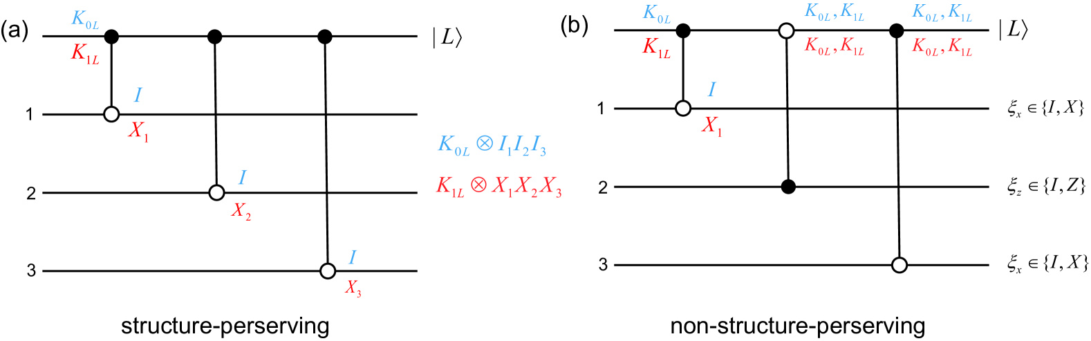
Our analysis of Rydberg decay is partially based on our previous work [7]. One feature of Rydberg decay is that it can be modeled as a leaked state that is not involved in subsequent two-qubit gate, no matter if the atom is lost from anti-trapping of atoms in Rydberg state [6, 5] or is leaked onto states that is energetically separated from qubit subspace [8, 6]. With pauli twirling and randomized compiling [26], a leakage instance can be considered as two kinds of jump operator with equal probability and we derive the error propagation by forward propagation of error [7]. State generation circuit discussed in previous work is a simplified condition since it only haves CZ gate and the jump operator keeps its form after forward propagation [27]. When considering syndrome measurement circuit in toric code with SWAP-LRU, the form of jump operator is not kept so the properties of deterministic error propagation destroys and it needs additional consideration. A detailed derivation of error propagation property is in Appendix A and the conclusion is that: When the circuit is structure-preserving for the jump operator, the error propagation is deterministic, dependent on the jump operator; When the circuit is not structure-preserving, the error propagation degrades to tailored-pauli propagation [24]. However, tailored pauli propagation of leakage is not as harmful as a general depolarization leakage model because it does not degrade the error distance for toric code and its variants [28].
Another feature about Rydberg decay is the leakage&leakage instance. It comes from the fact that when one of the atoms decays to some lower level, the blockade effect fails so another atom is driven to Rydberg state with a probability and is converted to atom loss [8]. It suggests that data qubit and ancilla qubit encounters a leakage simultaneously with probability ( is the error rate of single two-qubit gate), when we treat decay error to lower levels and atom loss induced by anti-trapping potential uniformly [8]. We avoid this question in our previous work because a CZ gate with leakage-leakage instance introduce two leakage in different lattices (primal lattice and dual lattice) and the two lattices are decoded separately [7]. Such instance is harmful critical fault because it degrades the error distance when it happens at one certain error site, as discussed in Section III.
III Rydberg decay Error propagation in SWAP-LRU
In this section we discuss the error propagation in SWAP-LRU. We use toric code as a test bed because we don’t need to worry about how to deal with data qubits on the boundaries. But it can be readily extended to its variants. In syndrome measurement circuit with SWAP-LRU, the role of data qubit and ancilla qubit is exchanged before each round of measurement, see Fig.1. In a standard syndrome measurement circuit, data qubit is always unmeasured so the leaked data qubits are not removed and may spread additional errors. With SWAP-LRU, data leakage is detected and removed in each round of measurement and ancilla leakage is removed in the next round of measurement, when it acts as data qubit. Therefore, both data leakage and ancilla leakage are removed in two rounds. Final CNOT gate can be replaced by a feed-forward gate, which is implemented virtually by software correction [25, 18]. This replacement makes no difference to the error propagation but we don’t need to accounts for gate error for the final CNOT gate in each syndrome measurement. Equipped with the circuit in Fig.1(c), neither additional qubit nor gate is needed to remove leakage and renew the atoms.
We give a detailed analysis of error propagation in Appendix B. Based on that, we identify two conditions that needs additional consideration. One is that ancilla leakage introduce two consecutive rounds of measurement error and another is that leakage&leakage instance in the first CNOT gate of each round of measurement degrades the distance.
The first condition is not harmful. For a logical identity, pure timelike error does not convert the logical observable [29]. When considering fault-tolerant regime, we may have constant rounds of additional syndrome measurement to suppress logical error introduced by measurement error, as discussed in Section VI. Besides, correlated decoding technique can also be applied to reduce the rounds of measurement so it may not become a problem [30, 25].
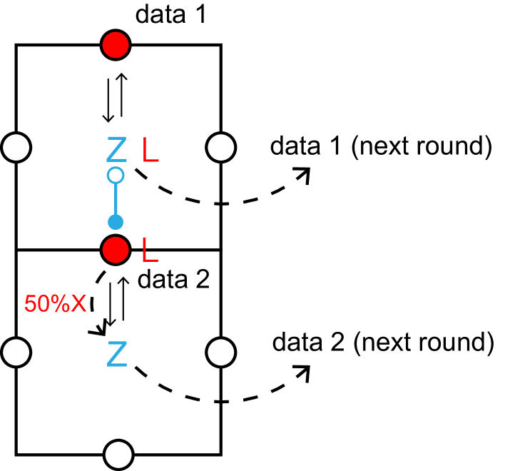
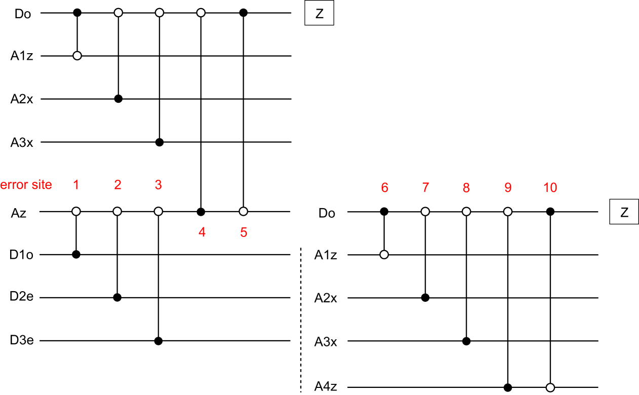
The second condition comes from leakage&leakage instance in neutral atoms two-qubit gate. See Fig.2, if leakage&leakage instance happens in the first CNOT gate, ancilla leakage becomes data leakage on the qubit that exchanges with the ancilla in the next round (data 1 in Fig.2) and data leakage propagates to 50% X error to ancilla qubit that exchanges with it, namely a 50% X error on that data qubit (data 2 in Fig.2) in the next round. These two data qubits, lie in the same logical X operator so this error degrades the distance. This discussion also applies to longitudinal logical Z operator when consider logical Z error. So this serves as a critical fault that does harm to performance of error correction [12] 333You can check such critical fault can not be eliminated by changing the gate sequence easily.
IV Error distance, located error and re-weighting
Error distance is the minimum number of physical (gate) error needed to generate a logical error. It is related to sub-threshold scaling of logical error rate. When physical error rate is small enough, logical error rate is suppressed exponentially with error distance , namely [32, 33]. Error distance is influenced by two factors. One is whether the error is located and another is whether single gate error induce two qubit error chain along the logical operator. The second factor is closely related to gate sequence and the form of error propagation [34, 32, 10, 12] and we have discussed the second factor for Rydberg decay in Sec.III. For the first factor, an error correction code with code distance corrects located errors (erasure errors) but pauli errors [8, 35]. ‘Located’ means that we know which qubits (or gates for detector error model [36]) are suspicious to be faulty so if a Rydberg decay error is detected and renewed we regard this as a erasure error [8]. Recently there are several works showing that approximately located error also has an error distance [24, 7, 18, 25]. Approximately located error corresponds to the conditions that use imperfect erasure check [24] or final erasure check (instead of erasure check after each gate) physically [7, 18, 25]. This insight inspires more hardware-efficient protocol regarding erasure error since additional erasure check comes along with additional hardware operation [8] or qubit overhead [18].
People has studied the performance of error correction for the mixture of pauli error () and erasure error (), in both threshold and sub-threshold scaling (effective error distance) [8, 16]. When the amount of error is comparable, logical error rate is governed by the more harmful error. So the effective error distance presents a clear advantage only if the ratio of erasure approximates 1 [8]. In another word, a small ratio of pauli error impacts on the distance drastically. This picture is similar when a more harmful error with error distance presents [9]. If not properly addressed, a small part of such error will pose a significant threat to sub-threshold scaling. Previous work has proposed to attach another LRU to deal with similar problem [12] while we deal with this problem from decoding perspective. Given the (approximate) located error has an distance , such error still has if the critical fault degrades the distance [24]. That is enough to guarantee the effectiveness of error correction since its distance is the same with pauli error. Therefore, all we need to do is to locate the critical fault.
To decode erasure error, one possible way is to adapt the weight of edges in decoding graph representing error mechanism according to the information of erased qubit, based on MPWM algorithm [36]. Erasure error is regarded as a completely mixed state, namely independent X and Z error with 50% probability. The weight is set to 0 so that the error is located when we try to find a minimum weight perfect matching [37]. Our work is based on approximate located error where we only use final leakage detection information to locate the error [24, 7, 18]. When the data qubits are measured in each round, three outcome measurement is applied to distinguish whether the qubit is leaked [7, 18, 11, 6, 5]. We infer the average error probability by considering total error probability summing over all possible error sites. For example, if a data qubit in even line is measured to be leaked, corresponding has to have 50% X error. We use this method to consider all possible error mechanisms and use pymatching to decode the re-weighted graph [38].
V Numerical Results
In this section we give some numerical results to demonstrate the performance of our protocol. In general, we consider two conditions and have compared three different decoders, including trivial decoder, located decoder and critical decoder. Trivial decoder means that we do not adapt the weight of decoding graph according to the result of leakage detection and is just for comparison. Located decoder means that we adapt the weight according to the detection of leakage, including atom loss and radiative decay [5]. Critical decoder means when we can only distinguish one type of leakage from qubit subspace, radiative decay or atom-loss we slightly modify the Located decoder to deal with critical fault. Critical decoder is motivated by the fact that leakage&leakage instance comes from decay & atom loss [8] and radiative decay is difficult to detect for alkali metal atoms because of the difficulty to distinguish different hyperfine levels [5].
Our simulation accounts for two-qubit gate error. For each CNOT gate, we assume it has probability to have Rydberg decay error and probability to have two-qubit depolarization error. The ratio of erasure (Rydberg decay) is defined as . For Rydberg decay, we draw an operator from . represents 50% pauli X or Z error according to the end of CNOT gate (control qubit: Z, target qubit: X) and represents with equal probability. for an ideal condition for comparison that only single-leakage instance exists and for a realistic condition 444Estimated for result in Supplementary Information S4 in [8], the ratio . It may varies according to atoms species and gate sequence but it should always be a small part. For two-qubit depolarization error, we draw an operator from . The procedure we deal with pauli error is discussed in Appendix C.
We discuss the performance of located decoder and trivial decoder in Sec.V.1 when both types of leakage can be detected. We first consider the performance when to show the threshold for pure Rydberg decay and clarify our discussion on sub-threshold scaling. Then we involve the performance when to show the advantages in performance compared to traditional error correction protocols. We discuss the performance of three decoders in Sec.V.2, when only one type of leakage is detected. We show that critical decoder effectively eliminates the detrimental effects of Rydberg decay with minimal hardware requirements. We demonstrate results of circuit in Fig.1(b) except for the threshold in Fig.3. We only accounts for logical error rate of longitudinal operator ( in Fig.S2) when considering error distance, otherwise we accounts for both operators. The code is available in [40].
V.1 Both Leakage Detected
First we consider the condition that both leakage can be detected. For alkali earth atoms such as , this requires we first detect the decay error to ground state and then do projective measurement in qubit subspace and distinguish atom loss at the same time [8, 14]. For alkali metal atom , an additional leakage detection units is needed if no efficient way to detect hyperfine leakage exists [6]. In this subsection we assume the leakage detection is perfect and imperfect leakage detection is included in Sec.V.2. And we only compare and discuss the performance of located decoder and trivial decoder.
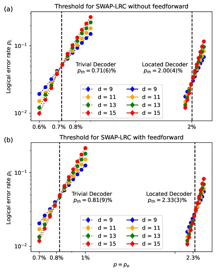
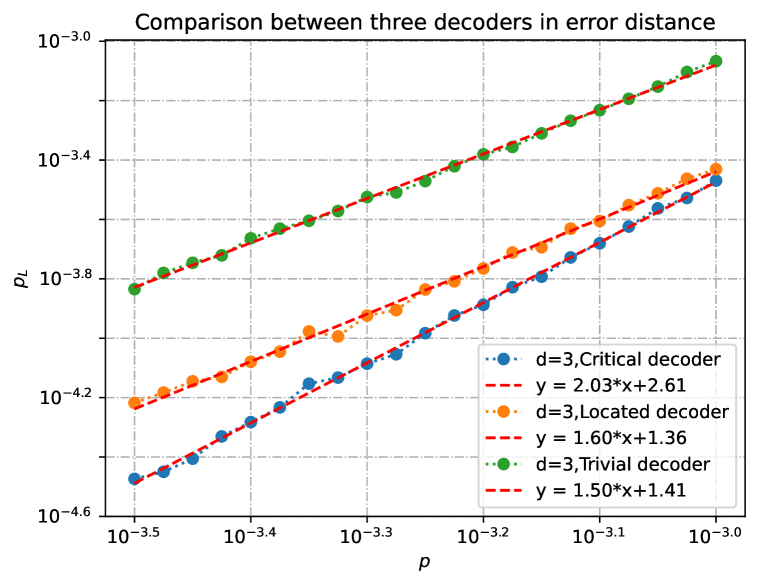
The result of threshold for pure Rydberg decay () is shown in Fig.3. We define a shot as rounds of syndrome measurement of toric code for distance , with SWAP-LRU. Both type of circuits are considered here and circuit with feed-forward gate achieves higher threshold because this circuit has fewer CNOT gates. The generated error and the error sites need to be accounted are fewer. We sampled shots for each point. We derive the threshold as critical point of phase transition from universal scaling ansatz with logical error rate near threshold for [41]. Fig.3 shows that located decoder has a greatly enhanced threshold over trivial decoder ( vs for circuit without feed-forward and vs for circuit with feed-forward) and it also has clear advantage over traditional pauli error ( for XZZX surface code without SWAP-LRC [8]).
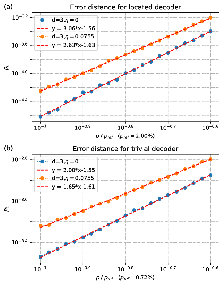
The result of sub-threshold performance and error distance for pure Rydberg decay is shown in Fig.4. Single leakage condition () is also drawn out for comparison. For located decoder and trivial decoder, we select the threshold derived in Fig.3 as a reference ( for located decoder and for trivial decoder). To derive (effective) error distance, we sample logical error rate from to , equally distributed in logscale. The result shows that error distance is highly sensitive toward worse scaling. However, because of the small branch, effective error distance still has an apparent advantage over traditional pauli error , which suggests better suppression of logical error for located decoder. But for trivial decoder, the distance is the same with pauli error without critical fault (). Once it exists, even a small fraction of leakage&leakage instance degrades the distance and does harm to the effectiveness of error correction.
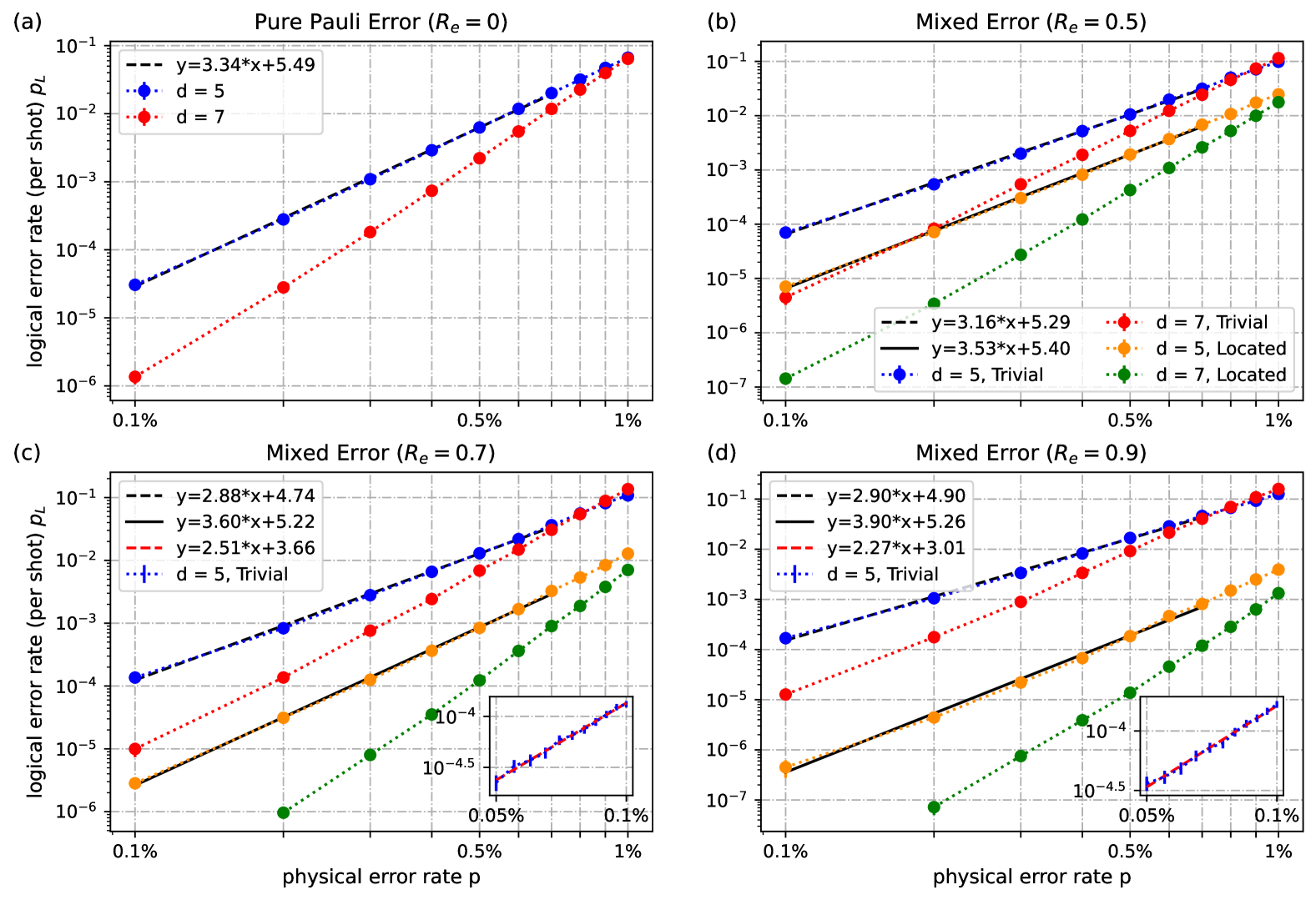
Then we come to consider a mixture of pauli error and leakage error from Rydberg decay. In neutral atoms, pauli error comes from not only Rydberg decay back to qubit-subspace but experimental imperfection as well, such as dephasing from imperfect laser pulse and atom heating. Although article [8] has an estimation of up to 98% for , the ratio only accounts for pauli error from Rydberg decay back to qubit-subspace. So realistic ratio should always be lower than and depends on specific experimental condition. Here we select and compare their performance with pure pauli (depolarization) error. We select an interested error range from to and each point is sampled for enough shots to suppress the error bar. For points for located decoder, we use a numerical technique used in [42] that only samples a part of leakage samples (2000 leakage samples for and 20000 leakage samples for ).
The results in Fig.5 reveal two things. For threshold, Rydberg decay has slightly lower threshold for trivial decoder compared to pauli error but higher threshold for located decoder. For sub-threshold scaling, Rydberg decay has slightly lower distance for trivial decoder compared to pauli error because of critical fault, but higher for located decoder since a large fraction of errors induced by Rydberg decay are located and do not degrade the distance. The difference (especially in sub-threshold scaling) enlarges when increases. Here we notice that the considered error rate is not enough to show the changes in error distance for trivial decoder when changes from 0.7 to 0.9 so we have extended the physical error range in to . The results for extended physical error range also reveal that even if the ratio of critical fault is small, it degrades the performance of sub-threshold scaling greatly when physical error rate is small enough. Combining the above two points, decoding Rydberg decay with located decoder has greatly improved performance over trivial decoder and traditional pauli error.
V.2 One Type of Leakage Detected
In this subsection, we introduce critical decoder that fits for more hardware-efficient implementation. We consider only one branch of Rydberg decay to be detected. This condition is of special interest because it is difficult to distinguish decay error into hyperfine levels for alkali metal atoms from qubit subspace, but atom loss from anti-trapping of atoms in Rydberg state can be detected [6, 23]. For alkaline-earth atom, it is also easier to detect one type of leakage than both [14]. The essence of critical decoder does not lie in improved performance over traditional pauli error, because the advantage needs a large branch of error to be detected leakage, which is difficult to realize when we only detects one type of leakage [8]. However, since the critical fault that degrade the distance is leakage&leakage instance during the first gate and it must be a decay error alone with atom loss, we assume that critical decoder is enough to locate the most harmful error, by converting its distance from to . So it serves as a hardware-efficient method to deal with Rydberg decay error.
In our critical decoder, we assume the undetected leakage is measured to be 0/1 with equal probability. We adapt critical decoder from located decoder by assuming that once a leakage is detected in each round, the probability that leakage&leakage instance is bound to happen after the first CNOT gate and re-weight the edges representing data qubit error. This over-estimate its probability but it guarantee that we can locate the critical fault. We compare the three decoders when and the ratio of detected leakage is . The result is shown in Fig.6. It reveals that only critical decoder preserves the distance. The difference lies in what kinds of errors a critical fault introduce. For trivial decoder, a critical fault introduce two non-located error alone one logical operator so it degrades the distance definitely. For located decoder, it introduce one located error and one non-located error. This condition is less harmful than the condition above but it still degrades the distance 555For , one or two critical faults are enough to introduce logical error for both trivial decoder and located decoder. For , three critical faults are needed to introduce a logical error while two critical faults are enough to introduce logical error. For all conditions, the error distance is lower than . Single critical fault is enough to introduce logical error in code. However, for critical decoder a critical fault introduces two located error. Since a code with distance corrects located error, at least is needed to introduce a logical error. Its error distance for critical fault is the same with traditional pauli error so it does not introduce additional harm to sub-threshold scaling.
VI Discussions and Conclusion
To some conclusions, our work has provide a novel and hardware-efficient protocol to deal with Rydberg decay error. We don’t need any additional operation from hardware perspective like erasure conversion in alkaline-earth metal atoms [8] nor addition ancilla qubits and CNOT gate to measure and renew the atoms [18]. The only required source is final three-outcome measurement that distinguishes leakage from qubit subspace to locate the error [5, 11, 6]. Three-outcome measurement has been demonstrated recently, which is a proof of the realizability of our protocol [6]. For pure Rydberg decay, we show a high threshold . We also consider more realistic condition where pauli error exists. It is believed that there is always trade-off between resource consumption and performance for any QEC protocol. However, even with modest hardware requirement, Rydberg decay is not only not harmful but also has enhanced performance compared to tradition pauli error, owing to the property of located error. And we then step further by considering the condition where only one type of leakage can be detected, which is of special practical interest [6, 23, 14]. We develop critical decoder motivated by the property of critical fault and located error [12] and show that it is enough to eliminate the harm of critical fault in sub-threshold scaling and preserves the distance [9].
Besides, we have provide some new perspectives on located error [35]. When considering the propagation of leakage error, the distance degrades for some conditions [10, 11, 12, 9]. In neutral atoms, such error refers to leakage&leakage instance which is inherent to the platform if we deal with the decay error and atom loss uniformly [8], for SWAP-LRU. To deal with similar problem, previous works either emphasize on some specific form of propagation [28] or use additional LRU to remove the effect [12]. In our work, we just use the property of located error, converting the distance of such harmful error from to . After that, such error can not be more harmful than pauli error so we don’t need any additional resource to deal with it. The property of located error is used to guarantee the lower bound of performance instead of to chase of an upper bound of performance. This use of located error is easier to present since the latter needs a large fraction of located error (), which is challenging to implement in experiment.
The performance in fault-tolerant scheme when time-like error begins to play a role needs discussion [29, 25]. In this scheme, logical error rate is also contributed by syndrome measurement error introduced by pauli noise and two consecutive rounds of measurement introduce by Rydberg decay error. However, following similar discussion on space-like degraded located error and pauli error, we expect that the performance is not greatly degraded as two consecutive rounds of measurement as located error also has a distance (with rounds of measurement) [44]. Another possible problem is that such error is introduced by single-leakage instance, which is not a small part of error. This problem is dealt with additional constant rounds of measurement, to suppress the logical error induced by time-like error so that space-like pauli error is the most harmful one.
For future directions, we first expect our work to inspire more hardware-efficient protocol in error correction to deal with leakage error in different systems [45]. From decoding aspects, we may combine the re-weighting process with BP to achieves higher accuracy [46]. We are also interested in considering the effect of Rydberg decay in fault-tolerant scheme, by combining correlated decoding techniques to further reduce the overhead.
Note.- There is a competitive and parallel work [25] that examines the performance of atom loss in fault-tolerant algorithms. Even though the thinking is similar in our decoding, these two works vary a lot in details and goals. The core advantages of our work are that we have considered a more specific and faithful two-qubit error model and our decoding is matching-based so it can be extended to large scale.
ACKNOWLEDGMENTS The authors especially thank Zi-Han Chen on detailed, insightful discussion and we also thank Si-Yuan Chen on discussion about coding techniques; Pai Peng on discussion of reasonability of error model and Zhao-Qiu Zeng-Xu on discussion on the practicability of the partially located decoder.
References
- [1] M. Saffman, T. G. Walker, and K. Mølmer. Quantum information with rydberg atoms. Rev. Mod. Phys., 82:2313–2363, Aug 2010.
- [2] M Morgado and S Whitlock. Quantum simulation and computing with rydberg-interacting qubits. AVS Quantum Science, 3(2), 2021.
- [3] Adam M Kaufman and Kang-Kuen Ni. Quantum science with optical tweezer arrays of ultracold atoms and molecules. Nature Physics, 17(12):1324–1333, 2021.
- [4] Xiaoling Wu, Xinhui Liang, Yaoqi Tian, Fan Yang, Cheng Chen, Yong-Chun Liu, Meng Khoon Tey, and Li You. A concise review of rydberg atom based quantum computation and quantum simulation, 2021.
- [5] Iris Cong, Harry Levine, Alexander Keesling, Dolev Bluvstein, Sheng-Tao Wang, and Mikhail D Lukin. Hardware-efficient, fault-tolerant quantum computation with rydberg atoms. Physical Review X, 12(2):021049, 2022.
- [6] Matthew N. H. Chow, Vikas Buchemmavari, Sivaprasad Omanakuttan, Bethany J. Little, Saurabh Pandey, Ivan H. Deutsch, and Yuan-Yu Jau. Circuit-based leakage-to-erasure conversion in a neutral atom quantum processor, 2024.
- [7] Cheng-Cheng Yu, Zi-Han Chen, Yu-Hao Deng, Ming-Cheng Chen, Chao-Yang Lu, and Jian-Wei Pan. Processing and decoding rydberg leakage error with mbqc, 2024.
- [8] Yue Wu, Shimon Kolkowitz, Shruti Puri, and Jeff D Thompson. Erasure conversion for fault-tolerant quantum computing in alkaline earth rydberg atom arrays. Nature communications, 13(1):4657, 2022.
- [9] Sven Jandura and Guido Pupillo. Surface code stabilizer measurements for rydberg atoms, 2024.
- [10] Austin G. Fowler. Coping with qubit leakage in topological codes. Phys. Rev. A, 88:042308, Oct 2013.
- [11] Martin Suchara, Andrew W Cross, and Jay M Gambetta. Leakage suppression in the toric code. In 2015 IEEE International Symposium on Information Theory (ISIT), pages 1119–1123. IEEE, 2015.
- [12] Natalie C Brown, Andrew Cross, and Kenneth R Brown. Critical faults of leakage errors on the surface code. In 2020 IEEE International Conference on Quantum Computing and Engineering (QCE), pages 286–294. IEEE, 2020.
- [13] Mingyu Kang, Wesley C Campbell, and Kenneth R Brown. Quantum error correction with metastable states of trapped ions using erasure conversion. PRX Quantum, 4(2):020358, 2023.
- [14] Shuo Ma, Genyue Liu, Pai Peng, Bichen Zhang, Sven Jandura, Jahan Claes, Alex P Burgers, Guido Pupillo, Shruti Puri, and Jeff D Thompson. High-fidelity gates and mid-circuit erasure conversion in an atomic qubit. Nature, 622(7982):279–284, 2023.
- [15] Pascal Scholl, Adam L Shaw, Richard Bing-Shiun Tsai, Ran Finkelstein, Joonhee Choi, and Manuel Endres. Erasure conversion in a high-fidelity rydberg quantum simulator. Nature, 622(7982):273–278, 2023.
- [16] Kaavya Sahay, Junlan Jin, Jahan Claes, Jeff D Thompson, and Shruti Puri. High-threshold codes for neutral-atom qubits with biased erasure errors. Physical Review X, 13(4):041013, 2023.
- [17] Sivaprasad Omanakuttan, Vikas Buchemmavari, Michael J. Martin, and Ivan H Deutsch. Coherence preserving leakage detection and cooling in alkaline earth atoms, 2024.
- [18] Hugo Perrin, Sven Jandura, and Guido Pupillo. Quantum error correction resilient against atom loss, 2024.
- [19] Sometimes this is also refered to SWAP-LRC(LeakageReductionCircuit) or Quick-LRU/LRC.
- [20] Matt McEwen, Dave Bacon, and Craig Gidney. Relaxing hardware requirements for surface code circuits using time-dynamics. Quantum, 7:1172, November 2023.
- [21] Google Quantum AI. Demonstrating dynamic surface codes, 2024.
- [22] Following the terminology in [12] we refer to certain error that degrades the distance as critical fault.
- [23] Simon J. Evered, Marcin Kalinowski, Alexandra A. Geim, Tom Manovitz, Dolev Bluvstein, Sophie H. Li, Nishad Maskara, Hengyun Zhou, Sepehr Ebadi, Muqing Xu, Joseph Campo, Madelyn Cain, Stefan Ostermann, Susanne F. Yelin, Subir Sachdev, Markus Greiner, Vladan Vuletić, and Mikhail D. Lukin. Probing topological matter and fermion dynamics on a neutral-atom quantum computer, 2025.
- [24] Kathleen Chang, Shraddha Singh, Jahan Claes, Kaavya Sahay, James Teoh, and Shruti Puri. Surface code with imperfect erasure checks, 2024.
- [25] Gefen Baranes, Madelyn Cain, J. Pablo Bonilla Ataides, Dolev Bluvstein, Josiah Sinclair, Vladan Vuletic, Hengyun Zhou, and Mikhail D. Lukin. Leveraging atom loss errors in fault tolerant quantum algorithms, 2025.
- [26] Joel J. Wallman and Joseph Emerson. Noise tailoring for scalable quantum computation via randomized compiling. Physical Review A, 94(5), November 2016.
- [27] Akshaya Jayashankar, My Duy Hoang Long, Hui Khoon Ng, and Prabha Mandayam. Achieving fault tolerance against amplitude-damping noise. Physical Review Research, 4(2):023034, 2022.
- [28] Natalie C. Brown and Kenneth R. Brown. Leakage mitigation for quantum error correction using a mixed qubit scheme. Phys. Rev. A, 100:032325, Sep 2019.
- [29] What is a “temporal” or “timelike” logical error in the surface code? https://quantumcomputing.stackexchange.com/questions/16057/what-is-a-temporal-or-timelike-logical-/error-in-the-surface-code.
- [30] Madelyn Cain, Chen Zhao, Hengyun Zhou, Nadine Meister, J. Pablo Bonilla Ataides, Arthur Jaffe, Dolev Bluvstein, and Mikhail D. Lukin. Correlated decoding of logical algorithms with transversal gates, 2024.
- [31] You can check such critical fault can not be eliminated by changing the gate sequence easily.
- [32] Anthony Ryan O’Rourke and Simon Devitt. Compare the pair: Rotated vs. unrotated surface codes at equal logical error rates, 2024.
- [33] Austin G. Fowler, Matteo Mariantoni, John M. Martinis, and Andrew N. Cleland. Surface codes: Towards practical large-scale quantum computation. Phys. Rev. A, 86:032324, Sep 2012.
- [34] Yu Tomita and Krysta M. Svore. Low-distance surface codes under realistic quantum noise. Physical Review A, 90(6), December 2014.
- [35] Michael A. Nielsen and Isaac L. Chuang. Quantum Computation and Quantum Information: 10th Anniversary Edition. Cambridge University Press, 2010.
- [36] Craig Gidney. Stim: a fast stabilizer circuit simulator. Quantum, 5:497, July 2021.
- [37] Yue Wu and Lin Zhong. Fusion blossom: Fast mwpm decoders for qec, 2023.
- [38] Oscar Higgott. Pymatching: A python package for decoding quantum codes with minimum-weight perfect matching, 2021.
- [39] Estimated for result in Supplementary Information S4 in [8], the ratio .
- [40] Available code for this work. https://github.com/yuchengcheng720/Located-decoder-for-Rydberg-decay.
- [41] Chenyang Wang, Jim Harrington, and John Preskill. Confinement-higgs transition in a disordered gauge theory and the accuracy threshold for quantum memory. Annals of Physics, 303(1):31–58, January 2003.
- [42] Shouzhen Gu, Yotam Vaknin, Alex Retzker, and Aleksander Kubica. Optimizing quantum error correction protocols with erasure qubits, 2024.
- [43] For , one or two critical faults are enough to introduce logical error for both trivial decoder and located decoder. For , three critical faults are needed to introduce a logical error while two critical faults are enough to introduce logical error. For all conditions, the error distance is lower than .
- [44] J Pablo Bonilla Ataides, David K Tuckett, Stephen D Bartlett, Steven T Flammia, and Benjamin J Brown. The xzzx surface code. Nature communications, 12(1):2172, 2021.
- [45] Aleksander Kubica, Arbel Haim, Yotam Vaknin, Harry Levine, Fernando Brandão, and Alex Retzker. Erasure qubits: Overcoming the limit in superconducting circuits. Phys. Rev. X, 13:041022, Nov 2023.
- [46] Oscar Higgott, Thomas C. Bohdanowicz, Aleksander Kubica, Steven T. Flammia, and Earl T. Campbell. Improved decoding of circuit noise and fragile boundaries of tailored surface codes, 2023.
Appendix A Derivation of Error Propagation Property
In this appendix we derive the error propagation property of Rydberg decay. First, we briefly review how we deal with Rydberg decay. With two low-lying levels to encode a qubit and only is strongly coupled with Rydberg state, the channel of Rydberg decay is described in the operator-sum form, with two kraus operators [16, 5].
| (1) |
We refer to as no-jump operator and as jump operator in this article. We don’t consider the jump operators between qubit subspace that are modeled as pauli error with Pauli twirling approximation (PTA), because pauli errors are compatible with traditional error correction schemes. For radiative decay (RD), the leaked state is energetically separated from qubit subspace (For alkali metal atoms, additional magnetic field is needed). For blackbody radiation (BBR) or other mechanism that leads to residual Rydberg population, the leaked state represents lost atom because the atoms in Rydberg state are ejected by anti-trapping potential. Under both conditions the leaked state does not interact with another atom qubit through two-qubit gate so our scheme has dealt with RD and BBR uniformly.
As pointed out previously, when we apply pauli twirling and randomized compiling in the presence of leaked state , non-diagonal terms in process matrix are removed for no-jump evolution as usual while the jump evolution governed by representing biased erasure channel is converted to erasure channel governed by two kraus operators as below ()
| (2) |
When the leaked qubit is in the control of CNOT gate, commutes with CNOT gate and propagates to a X error to corresponding qubit. So when the leaked qubit is always the control, the form of jump operator is preserved and it propagates to for or for , as shown in Fig.S1(a). The condition is the same if the leaked qubit is always the target of CNOT gate, by altering the basis of kraus operator (from in eqn 2 to ). However, if above condition is not satisfied, the form of kraus operator is not preserved. For example, a in the target of CNOT gate generate both and as shown below (, here .)
| (3) | ||||
For the condition in Fig.S1(b), the forward propagation of operator and are given as below (The right arrow represents forward propagation, namely an operator before some unitary gate equals to after this gate.)
| (4) | ||||
| (5) | ||||
The resulting noisy channel gives
| (6) | ||||
In the first right arrow, we have dropped all non-diagonal term because of pauli twirling in qubit 1,2,3. In the equation, we have make use of (). is dependent on the density matrix before its leakage. During randomized compiling the ensemble is a completely mixed state so . So the leaked qubit propagates to independent 50% X or Z error to corresponding qubits, namely a kind of tailored pauli propagation.
Appendix B Error propagation of SWAP-LRU
In this appendix, we consider the error propagation in details for toric code with SWAP-LRU. First, the schematic diagram of toric code Fig.S2 is shown below. After each round of syndrome measurement, ancilla qubit for syndrome measurement becomes data qubit for the next round. Namely, data qubits in odd lines exchange with ancilla qubits for Z syndrome measure right below them and data qubits in even lines exchange with ancilla qubits for X syndrome measure right below them.
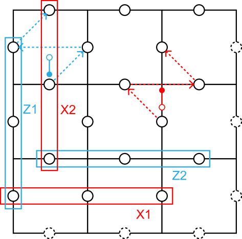
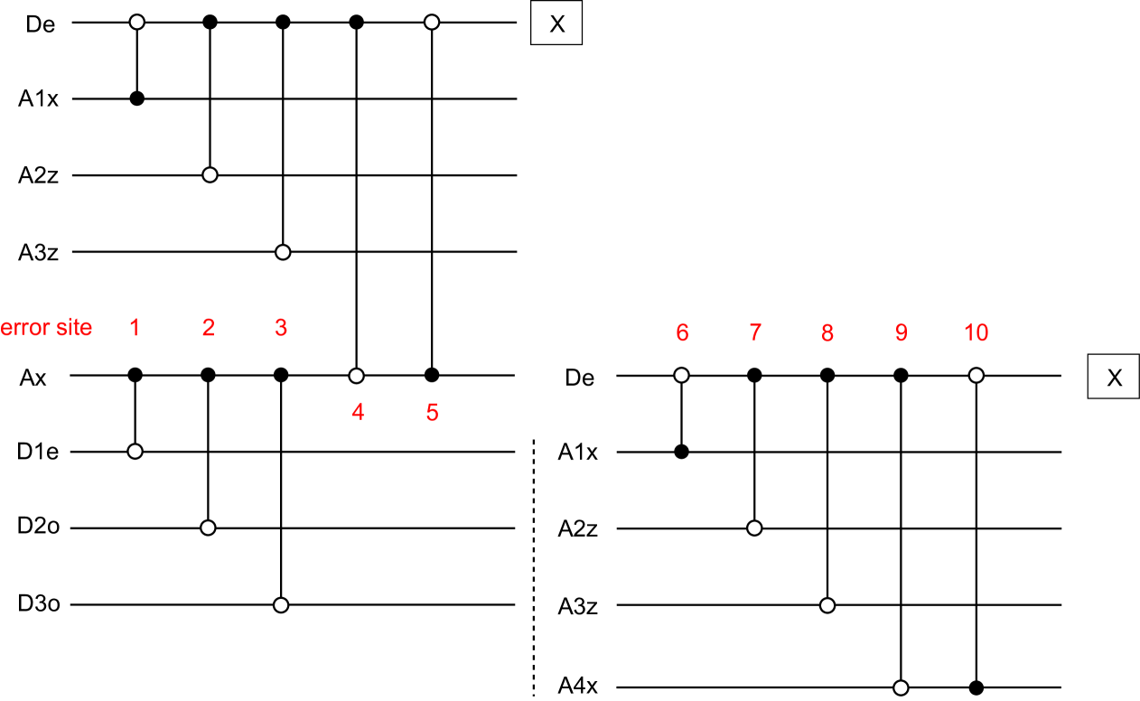
We have plotted all possible error sites and related CNOT gates and qubits if the measured data qubit is leaked. Data qubits in even lines are shown in Fig S3 and data qubits in odd lines are shown in Fig S4. In our consideration, we only consider logical X error because logical Z error is derived in the same way. When considering logical X error, we need to concern X errors (or leakage) in data qubits and Z syndrome measurement error (or leakage). We assume the syndrome measurement is repeated for d rounds and in the final round of measurement, data qubits are measured ideally (together with the information whether the qubit is leaked.)
| Error site | Generated error |
|---|---|
| 1 | |
| 2 | |
| 3 | |
| 4 | |
| 5 | |
| 6 | |
| 7 | |
| 8 | |
| 9 | |
| 10 |
| Error site | Generated error |
|---|---|
| 1 | |
| 2 | |
| 3 | |
| 4 | |
| 5 | |
| 6 | |
| 7 | |
| 8 | |
| 9 | |
| 10 |
There are two kinds of error that need additional attention, both from possible error sites for or data qubits in odd lines and Z ancilla qubits. First is single leakage error in error site 1,2,3,4, which introduce successive measurement error . Such kind of time-like error does not bother when we implement a logical identity, the condition discussed in our main text. When extending our method to fault-tolerant regime, we assume addition constant rounds of measurement is enough to reach a acceptable performance and correlated decoding technique can also be applied to reduce the rounds of measurement [30]. Fault-tolerant regime with leaked state in presence is highly unexplored and is one of our future topic [25].
Another error comes from the specific dynamics of neutral atoms. If one atom decays to lower levels during a two-qubit gate, another atom is driven to Rydberg state with probability, resulting an atom loss error after the gate. See Supplementary Information S4 in [8] for details. This is a worse condition compared to independent leakage assumption because data qubit and ancilla qubit leak simultaneously with , instead of a second order small term . We name such condition as leakage&leakage instance. If a leakage&leakage instance happens in the first CNOT gate of Z syndrome measurement, leakage in ancilla qubit introduce data qubit error after this round (see error site 1 in Table A2) and leakage in data qubit introduce data qubit error after this round. These two qubits lies in the same X logical operator ( in Fig. S2). This suggests that when considering logical error rate of one logical operator, logical error rate of should be higher than that of . This also suggests that logical qubit is biased (logical qubit 1 is biased toward Z error and logical qubit 2 is biased toward X error). However, as discussed in the main text, leakage-leakage instance takes a small part of two-qubit gate error and the error site that degrades distance is limited, we still achieve high error distance even in the presence of leakage&leakage instance .
Appendix C Two-qubit depolarization in SWAP-LRU
In this appendix, we explain how we add pauli error into our simulation. The pauli error is modeled by two-qubit depolarization . For clarity, we only consider X error and Z syndrome measurement error and Z error can be considered in the same way. Here, we classify the pauli error into three types, depending on whether the pauli operator has an X operator in ancilla qubit or data qubit (If it does not have a X operator in both qubits, it acts trivially.) Namely we have , , as X-X type, X-I type and I-X type. Each type has probability for each CNOT gate. Then we analyse all possible gate errors independently, for both CNOT gates acting on X syndrome qubits and Z syndrome qubits. The results are listed in Table.A3 and Table.A4 and a schematic diagram in Fig. S5. All the errors is added to detector error model with stim [36].
| Type/Site | 1 | 2 | 3 | 4 | 5 |
|---|---|---|---|---|---|
| X-X type | |||||
| X-I type | |||||
| I-X type |
| Type/Site | 1 | 2 | 3 | 4 | 5 |
|---|---|---|---|---|---|
| X-X type | |||||
| X-I type | |||||
| I-X type |