T3: Multi-modal Tailless Triple-Flapping-Wing Robot
for Efficient Aerial and Terrestrial Locomotion
Abstract
Flapping-wing robots offer great versatility; however, achieving efficient multi-modal locomotion remains challenging. This paper presents the design, modeling, and experimentation of T3, a novel tailless flapping-wing robot with three pairs of independently actuated wings. Inspired by juvenile water striders, T3 incorporates bio-inspired elastic passive legs that effectively transmit vibrations generated during wing flapping, enabling ground movement without additional motors. This novel mechanism facilitates efficient multi-modal locomotion while minimizing actuator usage, reducing complexity, and enhancing performance. An SE(3)-based controller ensures precise trajectory tracking and seamless mode transition.
To validate T3’s effectiveness, we developed a fully functional prototype and conducted targeted modeling, real-world experiments, and benchmark comparisons. The results demonstrate the robot’s and controller’s outstanding performance, underscoring the potential of multi-modal flapping-wing technologies for future aerial-ground robotic applications.
I Introduction
The study of flapping-wing robots has garnered significant attention due to their promising applications in areas such as disaster rescue, environmental monitoring, urban exploration, and entertainment performances [1] [2] [3] [4]. However, these robots often face limitations in maneuverability and adaptability in complex environments [5] [6] [7]. To address these challenges, researchers have developed multi-modal flapping-wing robots capable of both aerial and terrestrial locomotion. This advancement enables robots to t diverse terrains and perform a wider range of tasks, thereby enhancing their versatility and effectiveness in real-world applications.
Integrating mechanisms from ground robots has become a common approach to achieving terrestrial mobility for multi-modal flapping-wing robots, due to their well-established reliability. However, equipping these robots with wheels [8] [9] and walking mechanisms [7] [9] [10] [11] often requires additional actuators compared to their flight-only configurations. This not only complicates the control system but also reduces the robot’s reliability and increases manufacturing and maintenance costs [12]. Moreover, this approach often results in inefficient multi-modal locomotion and switching.
Regarding aerial mobility, there is a growing trend in biomimetic research to achieve high levels of mimicry of natural organisms [5] [6]. For instance, some designs replicate insects by employing two sets of flapping mechanisms and two servos, while others mimic insects with two pairs of independent wings and two rotors [8]. Additionally, various bio-inspired designs have been developed, drawing inspiration from larger birds [10], hummingbirds [13], flying squirrels [14], ladybird beetles [15], and others. To achieve high levels of biomimicry and full attitude control in the air, existing studies often involve complex designs with numerous actuators, which can lead to inefficiency in multi-modal locomotion.
In summary, despite significant progress in both terrestrial and aerial mobility for multi-modal flapping-wing robots, challenges persist in achieving efficient multi-modal locomotion. This necessitates not only innovative designs but also novel motion and actuation methods that reduce complexity and enhance performance.
Building upon previous analysis, we present a multi-modal tailless flapping-wing robot equipped with bio-inspired elastic passive legs modeled after those of juvenile water striders, which are used for locomotion on the water’s surface [16] [17] [18]. This design leverages the robot’s wing vibrations to enable terrestrial locomotion, integrating various functionalities such as vertical takeoff, multi-degree-of-freedom flight, self-righting, terrestrial locomotion, and seamless mode transition—all achieved with just three actuators. The robot features three sets of annularly symmetric flapping-wing actuators for propulsion, with a total weight of . In flight mode, it reaches a maximum speed of , with a flight endurance of . In terrestrial mode, it achieves a top speed of and can sustain controlled locomotion for up to .
This design effectively addresses key challenges in both terrestrial and aerial mobility. By incorporating bio-inspired elastic passive legs, our approach utilizes wing vibrations for ground movement, eliminating the need for additional actuators. This not only simplifies the control system but also enhances reliability while reducing manufacturing and maintenance costs. In terms of aerial mobility, the three-winged configuration optimizes thrust generation and stability while maintaining a lightweight structure. Unlike conventional designs, which rely on numerous actuators for high-performance attitude control, our method reduces system complexity without compromising maneuverability. This innovative approach improves the efficiency of multi-modal locomotion and facilitates seamless transitions between aerial and terrestrial modes, advancing novel motion and actuation strategies in multi-modal flapping-wing robotics.
An SE(3)-based controller [20] ensures precise trajectory tracking and seamless mode transition. To validate the effectiveness of T3, we developed a fully functional prototype and conducted a series of real-world experiments, along with benchmark comparisons. The results demonstrate the exceptional performance of both the robot and its controller, highlighting the potential of multi-modal flapping-wing technologies for future aerial-ground robotic applications.
The contributions of the proposed robot T3 are summarized:
-
•
A novel bio-inspired elastic passive leg, modeled after the legs of juvenile water striders during their locomotion on the water’s surface, effectively transmits the vibrations of the flapping wings. This design leverages the vibrations generated during flapping-wing actuation to drive the elastic passive leg, enabling terrestrial locomotion for the first time.
-
•
A novel tailless triple-flapping-wing robot integrated with bio-inspired elastic passive legs, enabling both aerial flight and ground crawling, along with seamless mode transition. Remarkably, these capabilities are achieved without the need for additional actuators dedicated solely to terrestrial locomotion.
-
•
An SE(3)-based controller that achieves precise tracking of aerial trajectories without active yaw control, along with seamless mode transitions.
-
•
A series of real-world experiments, and benchmark comparisons that demonstrate the outstanding performance of both the robot and its controller.
II Design of Multi-model Robot
II-A Bio-inspired Elastic Passive Leg
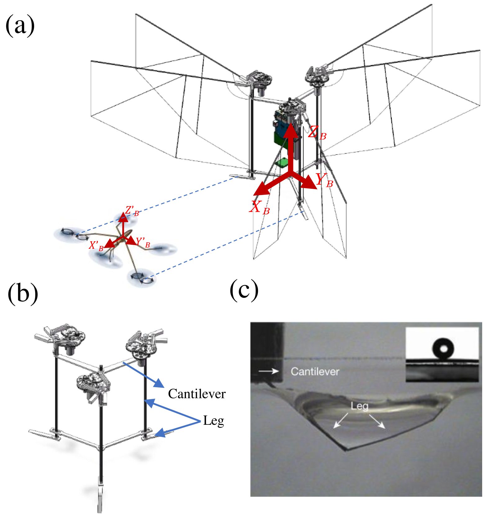
Water striders are exceptional insects known for their ability to generate propulsive vortices through rapid stroking motions of their long, specialized legs. This unique mechanism results in the formation of small whirlpools on the water’s surface, with the generated horseshoe vortex providing the force necessary to propel the insect forward. Exploiting this hydrodynamic effect, water striders are capable of gliding across the surface at impressive speeds [16] [17] [18], as depicted in Fig. 2(a), (c). A detailed structural analysis reveals that the insect possesses three pairs of elongated legs. Among these, the middle pair plays a crucial role in propulsion due to their larger size relative to the smaller front pair, which contributes minimally to the propulsion process. Additionally, the hind pair serves to stabilize the insect’s body, ensuring balance during locomotion and facilitating smooth gliding across the water’s surface [19], as depicted in Fig. 2(a).
In developing a terrestrial locomotion system, we propose a bio-inspired elastic passive leg mechanism that emulates the leg dynamics of water striders. The structural configuration is illustrated in Fig. 2(b). The system generates propulsive force through a motor-driven mechanism that actuates flapping-wing structures, while inducing vibrations. These vibrations are effectively transmitted through a lightweight carbon fiber rod structure to the support legs in contact with the ground. The support legs are designed with inherent elasticity to replicate the rapid stroking motion characteristic of water striders.
Both the primary leg structure and supporting limbs incorporate a degree of flexibility, optimizing energy transfer efficiency and enabling dynamic locomotion akin to the rapid leg movements of water striders on the water’s surface. By leveraging nature-inspired locomotion principles, this design achieves efficient propulsion while maintaining stability, offering insights into high-performance terrestrial robotic mobility.
A pair of symmetrically arranged bio-inspired elastic passive legs is implemented to replicate the primary propulsion mechanism exhibited by the middle legs of a water strider. These legs generate the majority of the propulsive force, emulating the rapid and efficient stroking motion that enables the insect to traverse the water surface. Additionally, a single centrally positioned bio-inspired elastic passive leg is integrated at the rear to enhance stability, analogous to the function of the hind legs in water striders, as illustrated in Fig. 2(a).
Unlike the water strider’s natural configuration, which employs two hind legs, this design utilizes a single stabilizing leg to reduce ground friction, improve maneuverability, and enhance overall walking stability. This simplification streamlines the control system and provides greater adaptability in movement, ultimately contributing to the efficiency and robustness of the locomotion system.
II-B Fly Mode of Triple-flapping-wing Robot
Previous research (Delfly series [21] [22]) has achieved controlled flight in two-winged and four-winged flapping-wing vehicles, though most designs require either additional actuators to twist wing trailing edges or pre-tilted wing arrangements to generate yaw torque - both approaches that compromise lift efficiency. Notably, yaw motion does not affect the upright stability of flapping-wing vehicles [23], and the flapping mechanism itself does not inherently induce vehicle rotation, since flapping-wing motion does not generate reactive torque similar to rotating rotor blades when producing lift. These characteristics enable the possibility of autonomous flight in triple-flapping-wing system without active yaw control.
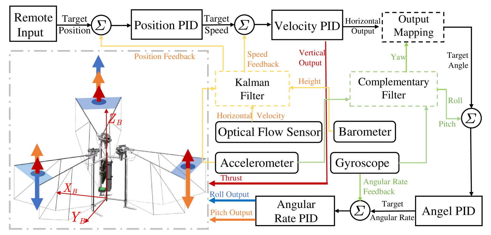
Stable closed-loop control of pitch and roll angles is the core of achieving hovering flight for tailless flapping-wing robots. This control is implemented through the cascaded structure of angular velocity PID controller and angle PID controller. Due to the lack of active yaw control, position control of this robot, in addition to position PID and velocity PID, also requires the allocation of velocity PID outputs based on the robot’s yaw angle. The flight control process of the robot under remote input is illustrated in Fig. 3.
However, the inherent issue of yaw angle drift poses a significant challenge to position control systems that rely exclusively on on-board control algorithms, potentially leading to a progressive degradation of flight stability over extended operational durations. Furthermore, the implementation of cascade controllers for trajectory tracking tasks inevitably introduces complexities in parameter tuning processes and a heightened risk of compromised flight stability.
Consequently, the robot is designed with a geometric trajectory tracking controller in SE(3) space that eliminates the need for active yaw control. By inputting the target position and the observed yaw angle, the outputs of the three motors are directly calculated.
First, we use and to describe the world frame and the body frame of the robot, respectively, and employ the sequence as the euler angle rotation order from to . The intermediate frame represents a temporary frame that has only undergone a yaw rotation [24]. As shown in Fig. 4, the rotation matrix from to can be given by , where represents the yaw rotation of the robot relative to , and represents the pitch and roll rotations of the body frame relative to . The control inputs of the system are described by , where represents the total lift provided by the three sets of flapping-wing modules, and , represent the torques around the axis and axis, the input matrix of the system is shown in Eq. (1).
| (1) |
Here, represent the flapping frequency of the back, left, and right flapping-wing modules, respectively. is the lift coefficient, and the subsequent experiments can demonstrate that the lift provided by each module is linearly related to the flapping frequency. is the length of the connecting arm from each flapping-wing module to the centre of mass, and is the angle between the left connecting arm and the positive direction of the axis.
Vector denotes the position vector of the body’s centre of mass in the world frame, represents the direction of gravity in the world frame, and denotes the direction of the lift output in the body frame. Then, we have:
| (2) |
From Eq. (2), we can derive the vector , where represents the gravitational acceleration. Additionally, Eq. (3) can be derived from Euler’s formula, where denotes the yaw torque that may arise due to the imbalance in the flapping-wing assembly and represents the robot’s inertia matrix.
| (3) |
The robot’s state is defined by , including its position, attitude, velocity, and angular velocity. In the absence of yaw control, we select the position variable as the flat output, and the yaw angle as an observable variable to assist in describing the system state.
In this case, the robot’s position, velocity and acceleration can be directly obtained from and its higher-order derivatives, while the robot’s attitude and angular velocity can also be derived through the rotation matrix .
From Eq. (2), the vector has already been obtained. As shown in Fig. 4, the vector can be expressed as , from which we can then derive:
| (4) |
Assuming that within the control limits of the pitch and roll, we will not encounter a situation where and are parallel, which means . Let denote the acceleration of the body. By differentiating Eq. (2), we obtain:
| (5) |
Let , and substituting into Eq. (5) yields:
| (6) |
Since , the angular velocities and can be further expressed as:
| (7) |
And can be expressed as:
| (8) |
Define the position error and velocity error as:
| (9) |
Next, calculate the desired force vector and the z-axis vector of the target position as follows:
| (10) |
and are proportional gain matrix of position and velocity , and can be given by Eq. (11), after substituting the observed yaw angle , other unit vectors in the body frame can also be obtained from Eq. (12), (13) and (14).
| (11) |
| (12) |
| (13) |
| (14) |
Therefore, the desired rotation matrix given by is obtained, and the orientation error is given by:
| (15) |
where denotes the Vee Map, which transforms an element of the Lie algebra into an element of the Lie group . The desired angular velocity of the robot can also be derived from Eq. (7) and Eq. (8). Based on this, we can calculate the angular velocity error as:
| (16) |
At this point, the other inputs and the torque on the axis can be calculated as:
| (17) |
and are proportional gain matrix of robot’s orientation and angular velocity. After completing the calculation of , the required motor speed to reach the target position can be determined by Eq. (1). Subsequently, the motor output can be computed, enabling the realization of geometric trajectory tracking control.
II-C System Architecture and Components
The flapping-wing robot consists of a carbon rod framework integrated with various electronic components and three sets of flapping-wing modules which are symmetrical in an annular arrangement. As illustrated in Fig. 5(b), each flapping-wing module employs a two-stage reduction gear set and a double crank-rocker mechanism to convert the rotational motion of a coreless motor into the flapping motion of the carbon rod at the leading edge of the wing. The gears and reduction gearbox are manufactured via injection molding, with a gear ratio of . The cranks, connecting rods, and rockers are fabricated using 3D printing, achieving a maximum flapping amplitude of .
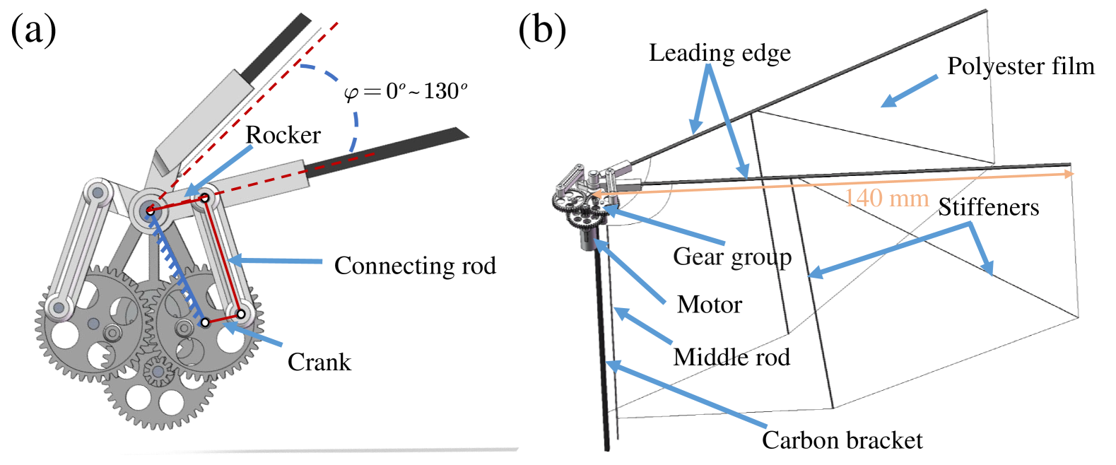
As shown in Fig. 5 (a), the flapping wings are designed based on the Wing8436 of the DelFly II [25], which exhibits a favorable lift-to-power ratio, with a wingspan of and an aspect ratio of . The leading edge of the wing is secured using a rectangular carbon rod with a thickness of , while the wing surface is made from thick polyester film, reinforced with diameter circular carbon rods as stiffeners. The flexible wing surface ensures that the leading edge motion always precedes the trailing edge, thereby better utilizing the clap-and-fling mechanism and the leading-edge vortex (LEV) to achieve higher lift efficiency. Each flapping-wing module is capable of generating flapping motions at frequencies up to , providing a maximum lift force of approximately . Three sets of flapping-wing modules can provide a maximum lift of for the robot, with a lift-to-weight ratio of .
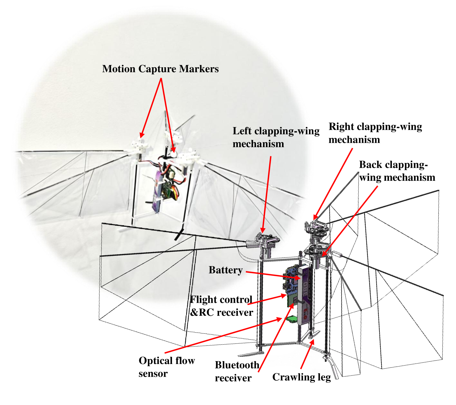
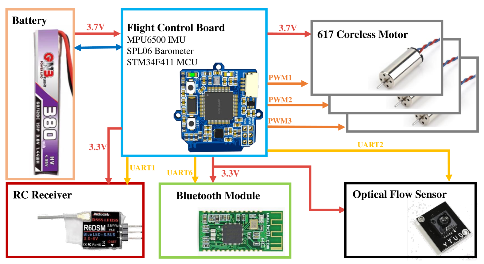
Each flapping-wing module is rigidly connected to the main carbon rod frame of the robot via a wide square carbon rod bracket. The electronic components of the robot body are illustrated in Fig. 6. The entire robot is powered by a 1S lithium battery and is equipped with a self-developed STM32 flight control board. This board integrates a MPU6500 gyroscope, a SPL06 barometer, a coreless motor driver circuit, and an optical flow communication circuit. Additionally, the board features interfaces for a Bluetooth module and a SBUS receiver, which are used for communication with the host computer and real-time signal reception from the remote control, respectively.
III Experiments and Results
III-A Crawling and Terrestrial Path Tracking
The ground crawling motion of micro-robots is often challenging to model systematically. In this study, the ground motion mode is primarily optimized through experimentation. Transforming the irregular vibrations of flapping-wing modules into controllable ground motion requires addressing two key issues: first, how to decouple the coupled vibrations of each flapping-wing module, and second, how to convert disordered vibrations into directional movement and rotation.
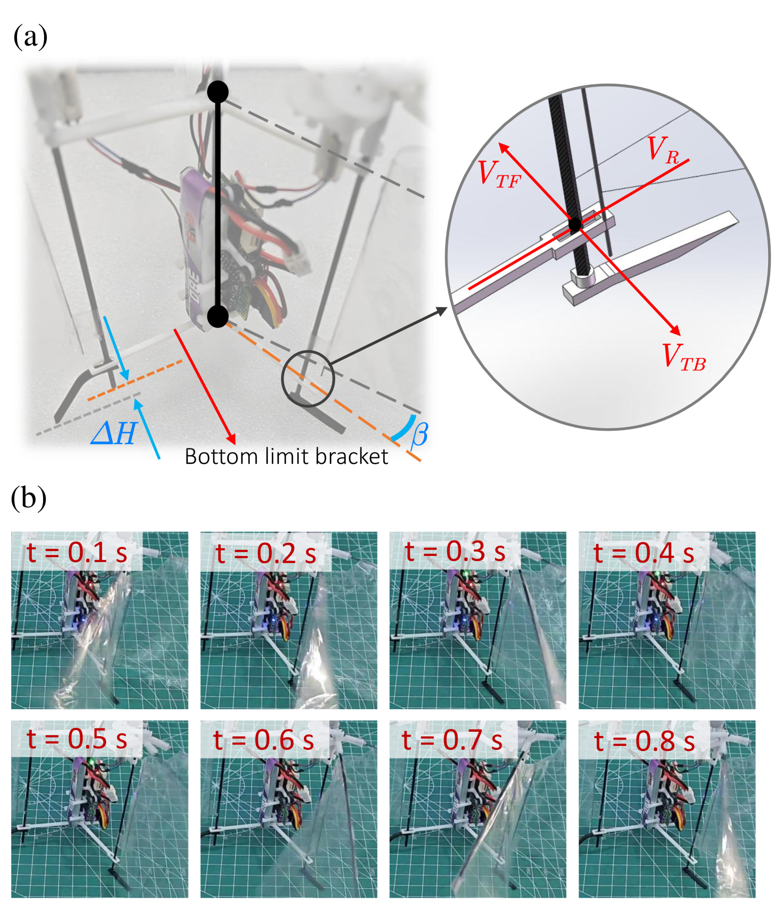
As shown in Fig. 7(a), a bottom limit bracket is used to isolate the vibrations of the flapping-wing modules. The terminal part of the limit bracket only constrains the tangential vibration at the bottom of the flapping-wing module while releasing the radial vibration , ensuring that only radial vibrations affect the robot’s body during flapping motion. Additionally, the left and right arms of the chassis limit bracket are not in the same plane as those of the main fixed bracket of the flapping-wing module but are inclined at an angle toward the rear flapping-wing module. Moreover, the crawling leg of the rear flapping-wing module is higher than the others. These two parameters amplify the driving effect of the front tangential vibration while mitigating the impact of the rear tangential vibration .
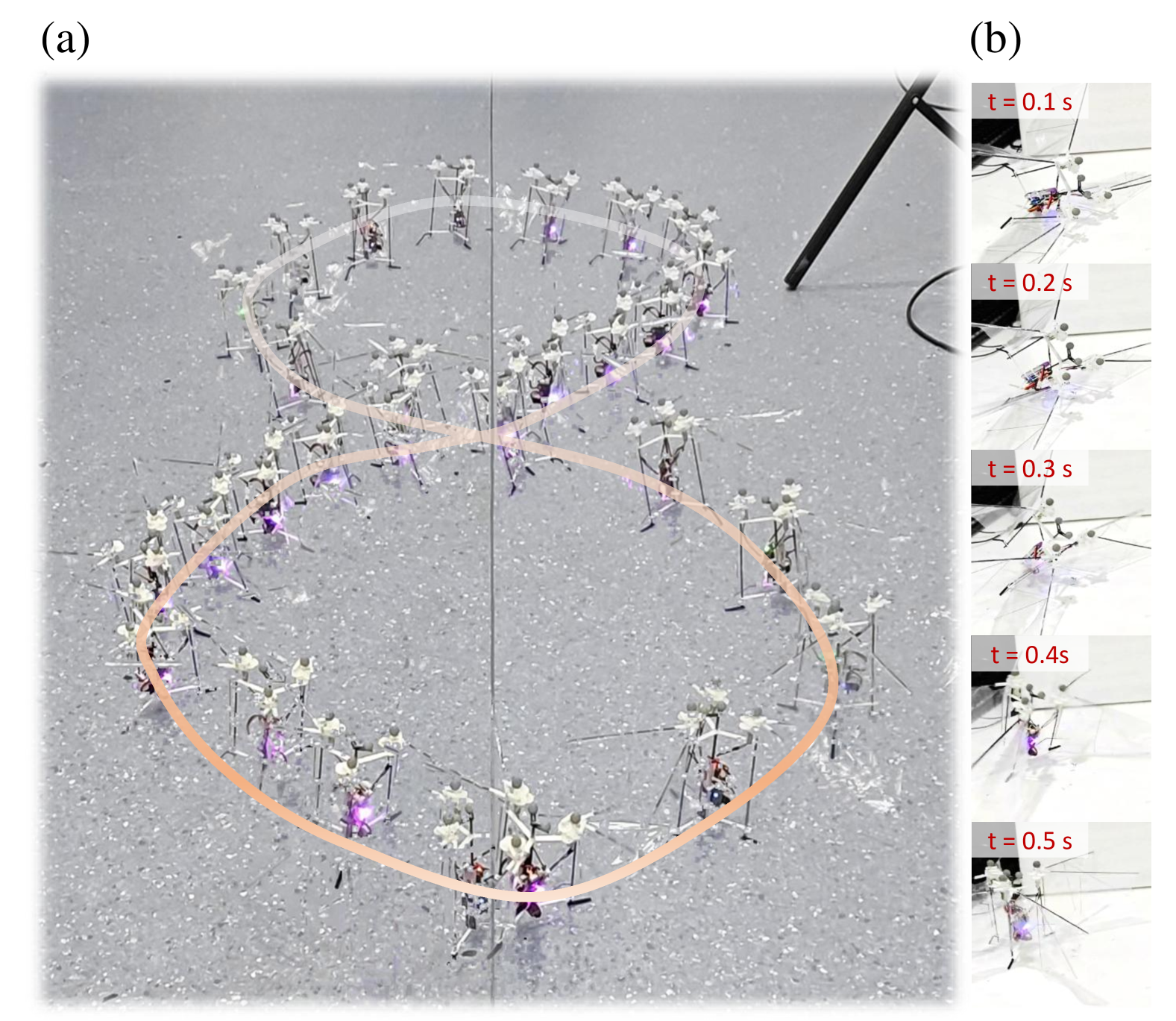
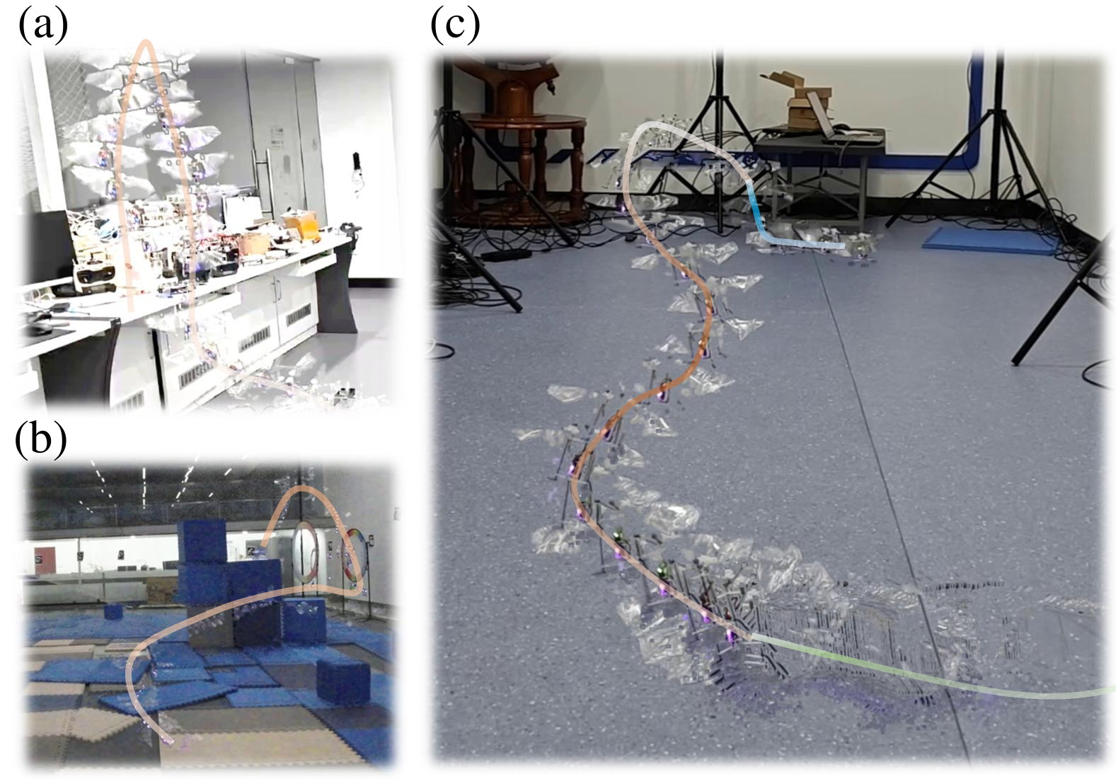
After optimizing the chassis structure, increasing the motor output of the right flapping-wing module enables the robot to generate forward motion and counterclockwise rotation, which is illustrated in Fig. 7(b). Coordinating with the left flapping-wing module allows for differential control, achieving ground movements such as forward motion and turning. The robot has also successfully completed the ground trajectory tracking experiment. As shown in Fig. 4(a), the yaw angle of the ground crawling motion was sampled by the host computer, and the target yaw is given by Eq. (18). The synthesized image of the 8-shaped trajectory tracking experiment is illustrated in Fig. 8(a).
| (18) |
III-B Thrust Generation, Self-Righting and Flight Endurance
In the process of controller modeling, it’s essential to quantify the relationships among the robot’s throttle output, wing flapping frequency, and lift generation. Experimental measurements under constant voltage supply conditions reveal a nonlinear relationship between the motor’s PWM throttle command and the wing flapping frequency, which can be characterized by a quadratic fit shown in Eq. (19). Additionally, the wing flapping frequency exhibits a linear relationship with the average lift generated by the module, with the fitting coefficient denoted as . The corresponding data is illustrated in Fig. 9.
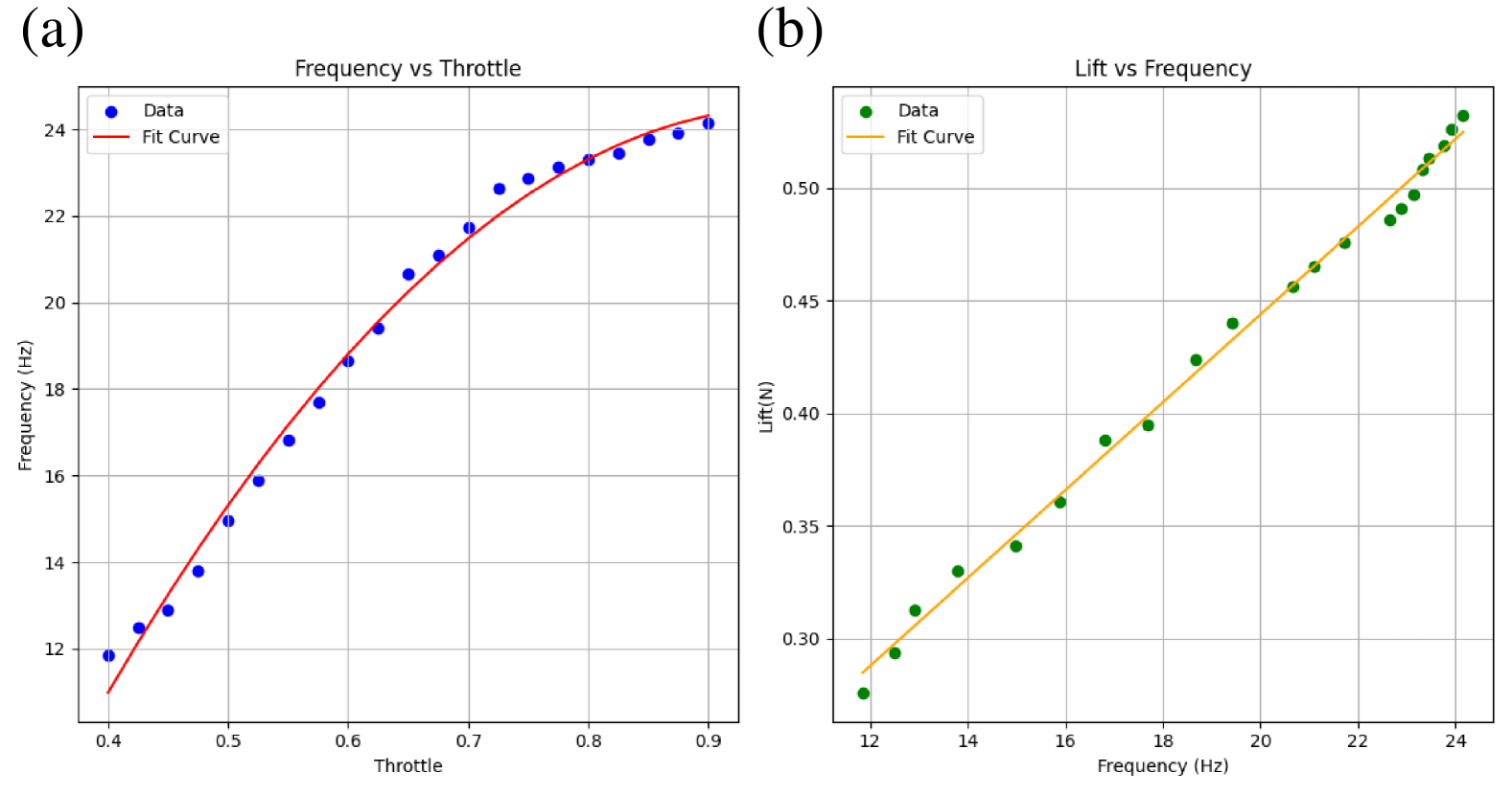
| (19) |
Furthermore, the robot’s wings have a large stroke angle of . When the robot tips over, it can detect its pitch and roll angles, then deploy the two sets of flapping-wing modules closest to the ground to achieve body self-righting. As shown in Fig. 8(b), experimental results demonstrate that the robot can complete the self-righting maneuver within , restoring itself to a functional posture.
We also measured the endurance time of the robot in both stationary hovering mode and ground mode at a constant speed of . Experimental results show that, with a fully charged battery, the robot’s endurance time from takeoff to the point where the battery can no longer sustain hovering is approximately . In contrast, the ground movement mode utilizes only two sets of flapping-wing modules, and the maximum vibration throttle is only half of that in hovering mode. As a result, the endurance time is significantly extended, reaching nearly four times that of the hovering mode, approximately .
III-C Remote Control Flight and Trajectory Tracking
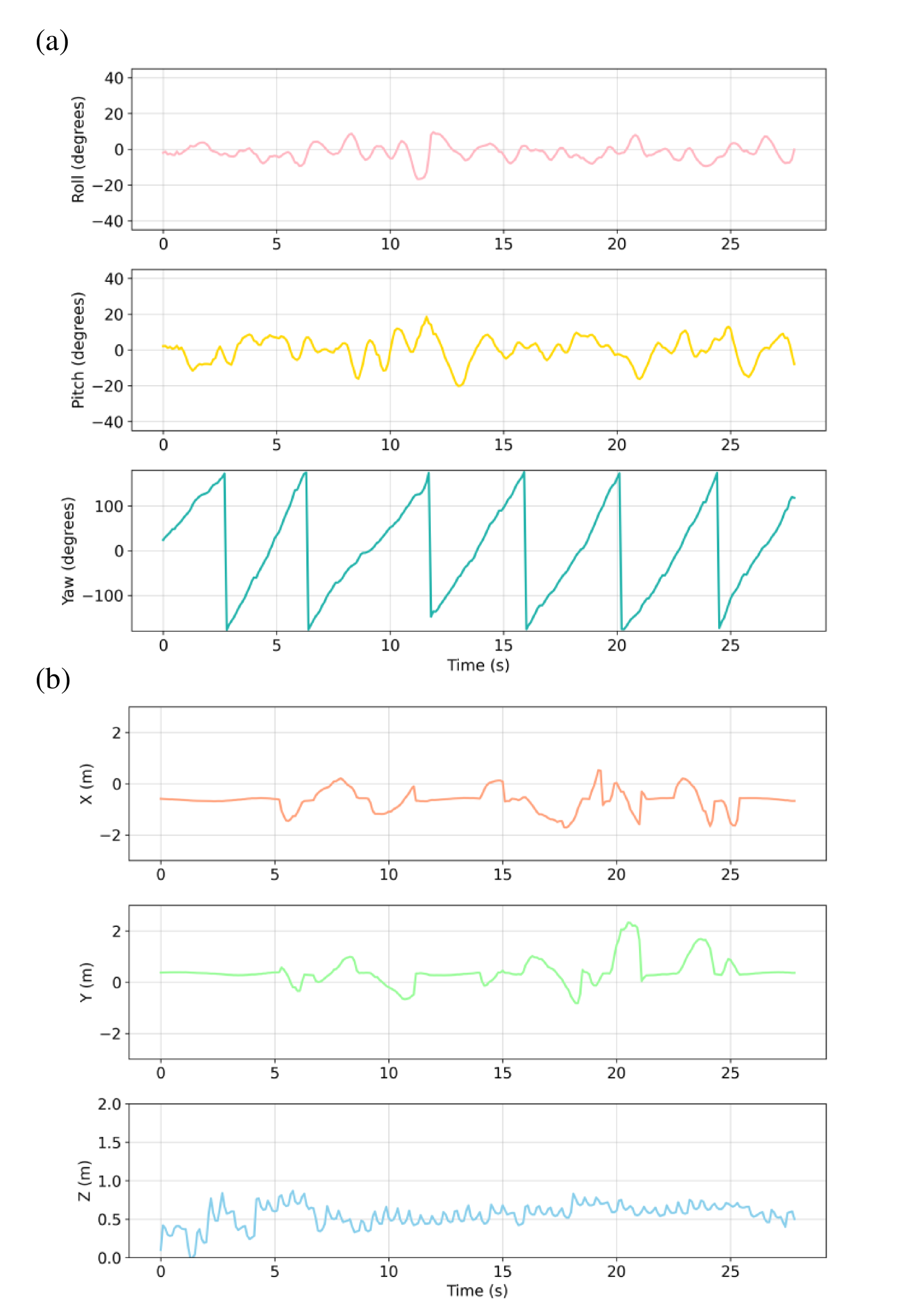
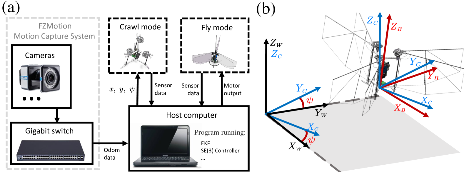
T3 robot successfully conducted a series of flight experiments, including vertical takeoff and landing, multi-DOF flight, and obstacle-crossing trajectory tracking. As depicted in Fig. 10(a), the robot maintained exceptional tracking performance in pitch and roll angles, even as the yaw angle exhibited periodic fluctuations in the absence of active yaw control. Fig. 10(b) presents the position data feedback obtained from the FZMotion motion capture system during the trajectory tracking experiment.
Fig. 11(a) demonstrates that the robot achieved stable flight control in altitude-hold mode by integrating multi-source data from onboard sensors. Fig. 11(b) further illustrates the robot’s trajectory tracking experiment assisted by the motion capture system, verifying its autonomous flight capability and stability. Fig. 11(c) shows the seamless transition of the robot from ground crawling mode to flight mode and then to vertical landing, indicating that the robot can achieve motion mode switching using the same set of actuators without altering its structure or posture.
IV Conclusion
This paper presents the design, modeling, and experimentation of a three-winged, tailless flapping robot named T3, which achieves ground crawling and flight through the vibrations and flapping motion of its own wings. With just three actuators, T3 combines features like self-righting, ground crawling, multi-DOF flight, vertical takeoff and landing, and smooth mode switching. The robot employs three sets of annular symmetrically arranged flapping-wing module, with an overall weight of . In flight mode, it achieves a maximum speed of and a flight endurance of . In ground mode, it reaches a maximum speed of and a crawling endurance of . Through a meticulously designed chassis mechanism and passive elastic legs, T3 constrains and enhances the vibrations generated by the flapping modules in specific directions, marking the first instance of a miniature biomimetic robot achieving controlled ground motion solely through its own wing vibrations. These results show that the design of T3 offers a novel and feasible solution for efficient insect-inspired flying and crawling robots.
References
- [1] G. C. De Croon, M. Groen, C. De Wagter, B. Remes, R. Ruijsink, and B. W. van Oudheusden, “Design, aerodynamics and autonomy of the delfly,” Bioinspiration & biomimetics, vol. 7, no. 2, p. 025003, 2012.
- [2] G. De Croon, M. Perçin, B. Remes, R. Ruijsink, and C. De Wagter, “The delfly,” Dordrecht: Springer Netherlands. doi, vol. 10, pp. 978–94, 2016.
- [3] K. Nguyen, L. T. K. Au, H.-V. Phan, S. H. Park, and H. C. Park, “Effects of wing kinematics, corrugation, and clap-and-fling on aerodynamic efficiency of a hovering insect-inspired flapping-wing micro air vehicle,” Aerospace Science and Technology, vol. 118, p. 106990, 2021.
- [4] K. Y. Scheper, M. Karásek, C. De Wagter, B. D. Remes, and G. C. De Croon, “First autonomous multi-room exploration with an insect-inspired flapping wing vehicle,” in 2018 IEEE International Conference on Robotics and Automation (ICRA), pp. 5546–5552, IEEE, 2018.
- [5] K. Low, T. Hu, S. Mohammed, J. Tangorra, and M. Kovac, “Perspectives on biologically inspired hybrid and multi-modal locomotion,” Bioinspiration & biomimetics, vol. 10, no. 2, p. 020301, 2015.
- [6] R. Lock, S. Burgess, and R. Vaidyanathan, “Multi-modal locomotion: from animal to application,” Bioinspiration & biomimetics, vol. 9, no. 1, p. 011001, 2013.
- [7] Z. Tu, C. Hui, L. Liu, Y. Zhou, D. R. Romano, and X. Deng, “Crawl and fly: A bio-inspired robot utilizing unified actuation for hybrid aerial-terrestrial locomotion,” IEEE Robotics and Automation Letters, vol. 6, no. 4, pp. 7549–7556, 2021.
- [8] Q. Li, H. Li, H. Shen, Y. Yu, H. He, X. Feng, Y. Sun, Z. Mao, G. Chen, Z. Tian, et al., “An aerial–wall robotic insect that can land, climb, and take off from vertical surfaces,” Research, vol. 6, p. 0144, 2023.
- [9] Y. Xu, W. Zhang, L. Peng, Q. Zhou, Q. Li, and Q. Shi, “A locust-inspired robot capable of continuous crawl-jump-gliding locomotion with optimized transitional control,” IEEE Transactions on Robotics, 2024.
- [10] W. D. Shin, H.-V. Phan, M. A. Daley, A. J. Ijspeert, and D. Floreano, “Fast ground-to-air transition with avian-inspired multifunctional legs,” Nature, vol. 636, no. 8041, pp. 86–91, 2024.
- [11] C. Wu, Y. Xiao, J. Zhao, J. Mou, F. Cui, and W. Liu, “A multi-modal tailless flapping-wing robot capable of flying, crawling, self-righting and horizontal take-off,” IEEE Robotics and Automation Letters, 2024.
- [12] Z. Zheng, Q. Cai, X. Xu, M. Cao, H. Yu, J. Li, G. Lu, and J. Wang, “Capsulebot: A novel compact hybrid aerial-ground robot with two actuated-wheel-rotors,” arXiv preprint arXiv:2309.09224, 2023.
- [13] F. Fei, Z. Tu, and X. Deng, “An at-scale tailless flapping wing hummingbird robot: Ii. flight control in hovering and trajectory tracking,” Bioinspiration & Biomimetics, vol. 18, no. 2, p. 026003, 2023.
- [14] W. D. Shin, J. Park, and H.-W. Park, “Bio-inspired design of a gliding-walking multi-modal robot,” in 2018 IEEE/RSJ International Conference on Intelligent Robots and Systems (IROS), pp. 8158–8164, IEEE, 2018.
- [15] S.-M. Baek, S. Yim, S.-H. Chae, D.-Y. Lee, and K.-J. Cho, “Ladybird beetle–inspired compliant origami,” Science Robotics, vol. 5, no. 41, p. eaaz6262, 2020.
- [16] M. Dickinson, “How to walk on water,” Nature, vol. 424, no. 6949, pp. 621–622, 2003.
- [17] D. L. Hu, B. Chan, and J. W. Bush, “The hydrodynamics of water strider locomotion,” nature, vol. 424, no. 6949, pp. 663–666, 2003.
- [18] X. Gao and L. Jiang, “Water-repellent legs of water striders,” nature, vol. 432, no. 7013, pp. 36–36, 2004.
- [19] P. Perez Goodwyn, J.-t. Wang, Z.-j. Wang, A.-h. Ji, Z.-d. Dai, and K. Fujisaki, “Water striders: the biomechanics of water locomotion and functional morphology of the hydrophobic surface (insecta: Hemiptera-heteroptera),” Journal of Bionic Engineering, vol. 5, no. 2, pp. 121–126, 2008.
- [20] T. Lee, M. Leok, and N. H. McClamroch, “Geometric tracking control of a quadrotor uav on se (3),” in 49th IEEE conference on decision and control (CDC), pp. 5420–5425, IEEE, 2010.
- [21] M. Karásek, F. T. Muijres, C. De Wagter, B. D. Remes, and G. C. De Croon, “A tailless aerial robotic flapper reveals that flies use torque coupling in rapid banked turns,” Science, vol. 361, no. 6407, pp. 1089–1094, 2018.
- [22] C. De Wagter, M. Karásek, and G. De Croon, “Quad-thopter: Tailless flapping wing robot with four pairs of wings,” International Journal of Micro Air Vehicles, vol. 10, no. 3, pp. 244–253, 2018.
- [23] H. V. Phan and H. C. Park, “Insect-inspired, tailless, hover-capable flapping-wing robots: Recent progress, challenges, and future directions,” Progress in Aerospace Sciences, vol. 111, p. 100573, 2019.
- [24] D. Mellinger and V. Kumar, “Minimum snap trajectory generation and control for quadrotors,” in 2011 IEEE international conference on robotics and automation, pp. 2520–2525, IEEE, 2011.
- [25] B. Bruggeman, “Improving flight performance of delfly ii in hover by improving wing design and driving mechanism,” Delft University of Technology M. Sc. thesis, 2010.