CAFEs: Cable-driven Collaborative Floating End-Effectors for Agriculture Applications
Abstract
CAFEs (Collaborative Agricultural Floating End-effectors) is a new robot design and control approach to automating large-scale agricultural tasks. Based upon a cable driven robot architecture, by sharing the same roller-driven cable set with modular robotic arms, a fast-switching clamping mechanism allows each CAFE to clamp onto or release from the moving cables, enabling both independent and synchronized movement across the workspace. The methods developed to enable this system include the mechanical design, precise position control and a dynamic model for the spring-mass liked system, ensuring accurate and stable movement of the robotic arms. The system’s scalability is further explored by studying the tension and sag in the cables to maintain performance as more robotic arms are deployed. Experimental and simulation results demonstrate the system’s effectiveness in tasks including pick-and-place showing its potential to contribute to agricultural automation.
I INTRODUCTION
Robotic systems in agriculture primarily rely on Unmanned Ground Vehicles (UGVs) for harvesting [1, 2, 3] and Unmanned Aerial Vehicles (UAVs) for monitoring and yield estimation [4, 5, 6, 7, 8]. While these systems effectively navigate complex farm environments, they rely on GPS, Real-Time Kinematic (RTK) positioning, Simultaneous Localization and Mapping (SLAM), or visual-inertial odometry for self-localization [9]. However, these localization methods can be intricate, adding to the challenges of cost, scalability, and coordination for large-scale deployment. A well-designed cable-driven mechanism could offer a viable alternative, reducing localization dependency while maintaining efficient coverage of agricultural fields.
Cable-driven robots offer an alternative approach by providing precise positioning without complex navigation [10, 11, 12]. Examples like SkyCam [13] and CU-brick [14] showcase their advantages in large spaces without the need for complex navigation, making them useful for agricultural work. However, traditional cable-driven robots are constrained by their scalability due to the limited number of end-effectors.The multi-robot coordination is challenging regarding to the cable interference [15]. Although reconfigurable cable robot [16, 17, 18] improve workspace flexibility, they introduce hardware and control complexities due to multiple interacting cables.
Suspended cable-driven systems can avoid some of these limitations, but they often suffer from limited workspaces near the ground [19] and require complex real-time control to mitigate oscillations [20, 21, 22]. Additionally, when scaling up these systems to tens or hundreds of meters, cable elongation and flexing under variable loads can introduce positioning errors in the centimeter range, while differential sagging affects precision, limiting their use in large-scale farming.

The challenges of using mobile and cable-driven systems highlight the need for a solution that can cover large areas and allow multiple robots to work together efficiently. We propose a cable-driven system for collaborative end effectors (CAFEs) that adresses these problems by introducing a cable-driven setup that allows several robotic arms to work together without requiring complex navigation or workspace rearrangement as shown in Figure 1. The proposed system leverages the advantages of cable-driven robots while enabling cooperation between multiple end-effectors, such as for harvesting tasks. It can be deployed in both greenhouses and outdoor fields by strategically placing multiple anchoring points. The system’s scalability is achieved by adding more CAFEs, incorporating additional cable sets, or extending the cable lengths.
The proposed cable-driven system features both passive cables and a commonly shared roller-driven cable that runs along the length of the floating structure. By providing each floating platform with the ability to independently clamp on and off (in either direction of the cable) we maintain the potential for independent operation whilst enabling far simpler synchronzied control as they can be moved by the same rollder-driven cable. Because the design allow multiple robots traversing on the the set of cable, such terrain-independent but still coordinated advantage is able to address the problem in both UGVs and UAVs. Also, the robotic arms can travel in the air with low energy consumption due to the shared weight on the cables. Furthermore, asthe actuation is provided by the shared moving cable each platform remains light weight and requires only clamping control. Specifically the contributions of this work include:
-
1.
A novel design of a cable traversing system that enables both individual and synchronized movement of multiple robots with simple logic control.
-
2.
Demonstration of the precise and repeatable position control of the system.
-
3.
Use of a dynamic model to analyze the tension distribution and scalability of the robot.
The subsequent section of this paper detail the robots design, control and dynamic behaviour. The experimental setup and results are then presented, finishing with a conclusion and discussion.
II METHODS
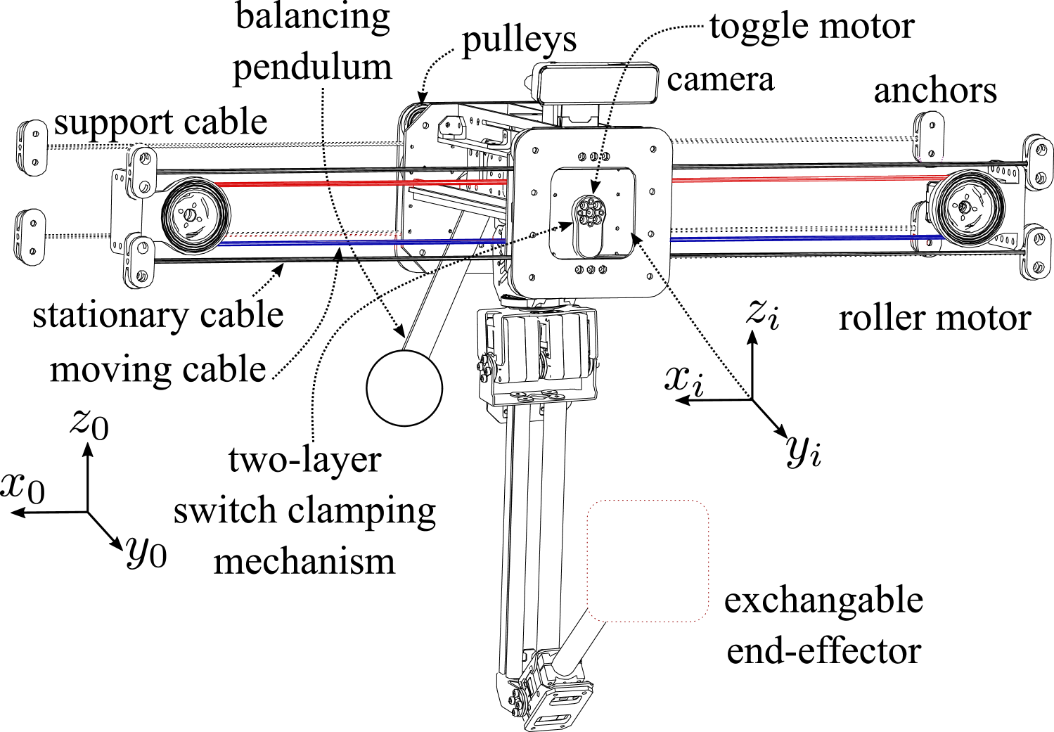
The proposed system (Figure 1) comprises multiple CAFEs mounted on a shared three-cable setup, with two stationary passive cables and one actively driven cable for movement. Each CAFE (Figure 2) integrates a robotic arm, clamping mechanism, and camera for harvesting, powered by an exchangeable LiPo battery that supplies the Raspberry Pi and servo motors. Wireless ROS2 communication ensures coordinated control. The cable set is anchored to a rigid structure and pre-tensioned based on cable sag, CAFEs count, and total length. The following section details the system’s design and control.
II-A Cable System and Operation Mode
The cable structure of the system has three main sets of cables, each serving a different purpose:
-
•
Continuously moving cable loop (red and blue color in Figure 2). This is driven by two roller motors, rotating at the same direction and providing both leftward (lower cable) and rightward (upper cable) motion to any attached CAFEs.
-
•
Stationary cable sets. Pretensioned and anchored at the cable ends, acting as motion stoppers for the robot and support the weight.
-
•
Load-supporting cable sets: Pretensioned and anchored at the cable ends, designed to support the robot’s weight only.
All CAFEs in the system share the three cable sets, reducing the need for extra components and powerful motors on the platform. This design has two advantages. First, it minimizes both cable sag and pretension caused by the accumulated robots’ weight. Secondly, it ensures synchronized movement for precise position control, avoiding slippage issues which are common in traditional cable-traversing robots with rolling wheels. The use of two roller motors guarantees sufficient torque to move multiple CAFEs efficiently along long cables.
(a) Individual CAFE
(b) Cooperative between CAFEs
(c) Mixed operation mode
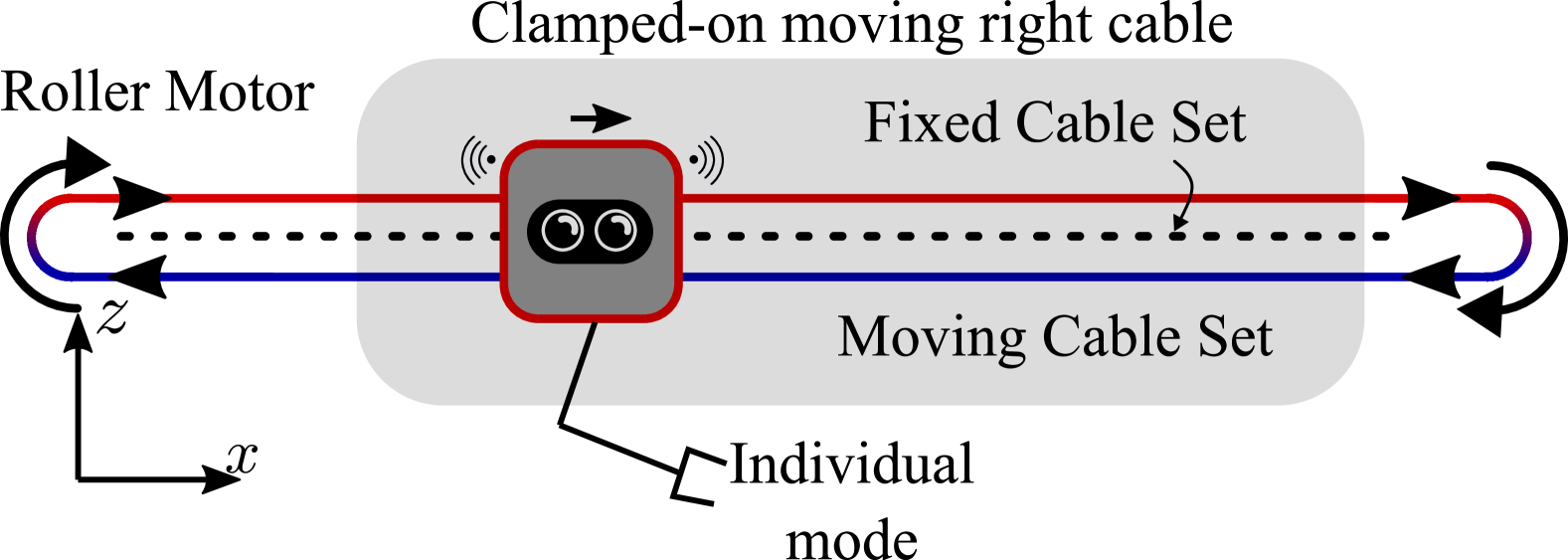
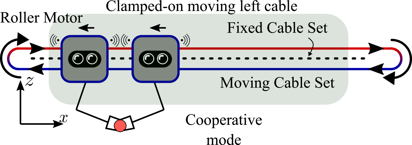
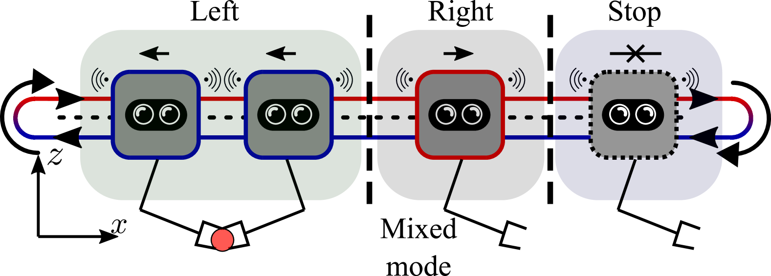
Each of the CAFEs can anchor on to the continuously moving cable or stationary cable. This enables a number of modes of operation for a multi-robot system which are summarized in Figure 3:
-
•
Indepedent Individual Mode. Each single lightweight CAFE can clamp on/off to the actuated/stationary cable having independent position control in either direction. This is useful when each arm is perform a different tasks, for example, crop inspection and monitoring in farms.
-
•
Cooperative Mode. When two or more CAFEs need to move a fixed distance together (in symmetry or anti-symmetry), by clamping on/off at the same time their separation distance can be guaranteed as they are being moved by the same driving cable. This is useful when the arms are performing bi-manual lifting, or a mirrored task.
-
•
Mixed Mode: Different CAFEs can operate in different modes along the cable system. We make the assumption that each robot, or set of robots will have a fixed area of operation.
II-B Switch Clamping Mechanism
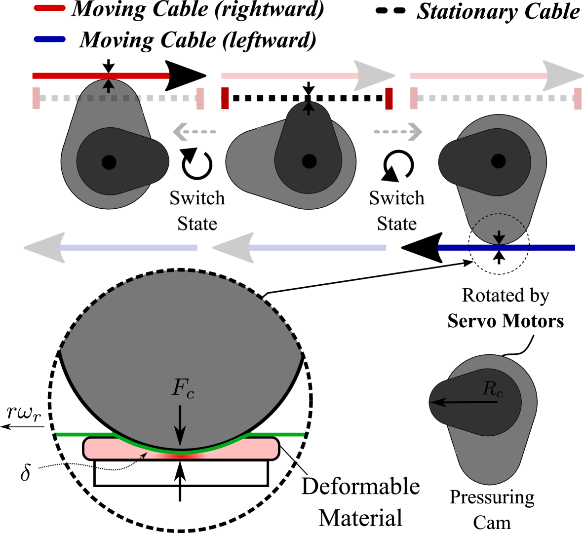
As shown in Figure 4, the roller motors and continuous cable provides two moving directions of the cables, and the stationary cable a third possible state. Thus, the robot requires a clamping mechanism which can enable anchoring to one of these there cables. This is performed with a pressuring cam (illustrated in Figure 4) which rotates to contacts the soft materials fixed on the robot. The clamping angles are , , and for three moving states: leftward, rightward, and stationary, respectively. The pressuring cam generating a normal force , which follows a relationship with material deformation , according to the Hertzian contact force equation to the elastic half-space:
where represents the radius of the pressuring cam, denotes the total deformation, and stands for the Young’s modulus ratio. Thus, the clamping force produces high friction, even without high cable tension, to anchor the robot on to the required cable. As such the robot can be securely hold at its position when needed without any additional control of energy.
II-C Floating Platform and position control
Each CAFE integrates components such as pulleys, a toggle motor with the clamping mechanism, a depth camera, and a counterbalancing system. The depth camera provides feedback for navigating toward the target region. In the next development, the depth camera is also used to deploy the vision tracking to locate the crops with the YOLO or other approaches. The counterbalancing system stabilizes the platform in response to the robotic arm’s movements. Driven by the roller motors with the same angular speed and a radius , the position of the CAFE is determined by
| (1) |
where , , and is the previous state’s position, moving direction, linear displacement of driving cable, and incline angle to horizontal, respectively. In addition, the linear displacement of driving cable is calculated by:
| (2) |
where and is clamping-on and clamping-off moment. is the roller angular velocity and denotes the roller’s radius. Precise positioning of the floating platform is achieved through simple logic control of the clamping timing.
II-D Dynamic System Model & Behaviour
The system can be modeled as a spring-mass system, where the horizontal cables act as springs and the CAFEs as masses. Cable sag affects the robot’s vertical position during traversal, necessitating an analysis of sag and oscillation dynamics for effective active position compensation, particularly in multi-CAFE setups.
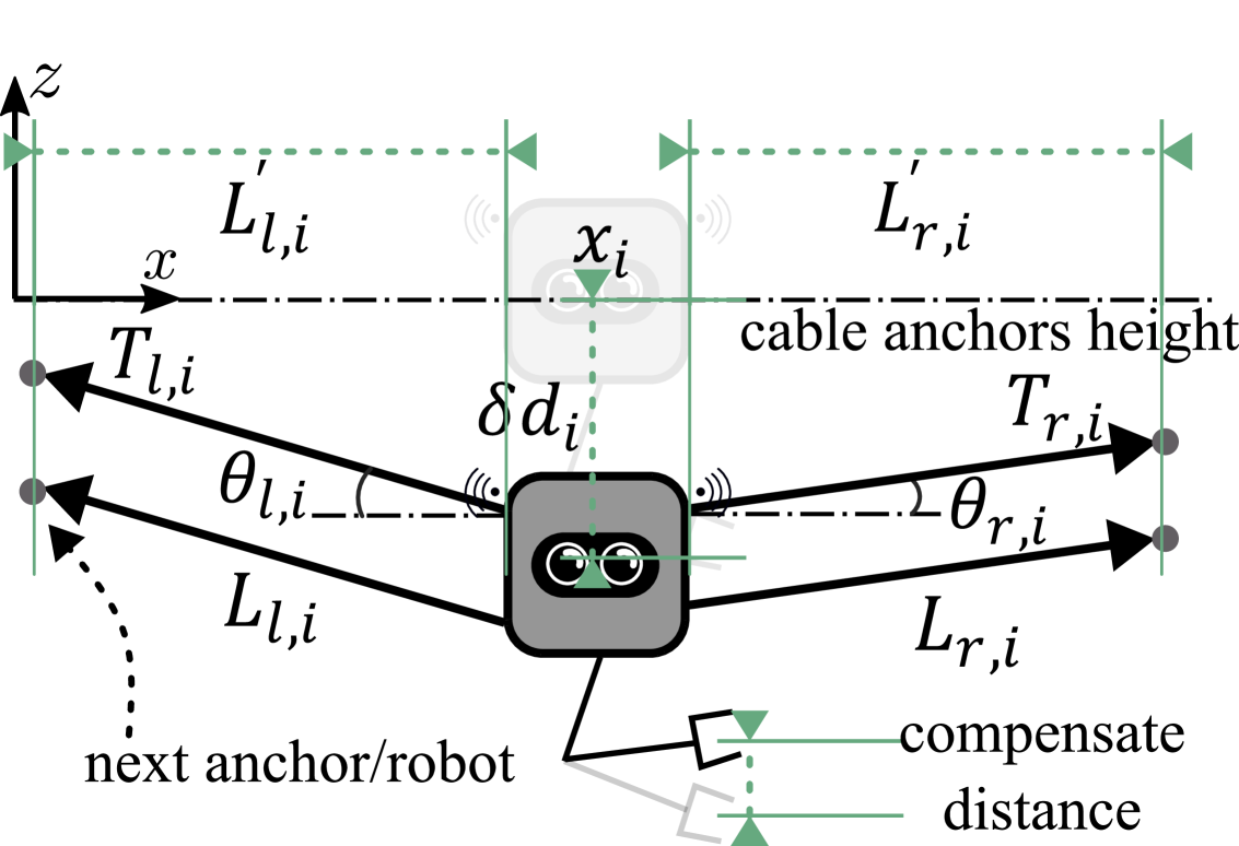
As shown in Figure 5, the CAFE will experience a vertical displacement of . The equation of motion for each individual CAFE can be expressed as
| (3) |
where , , , , , , , , and represent the acceleration, velocity, tensions, angles, mass, gravitational constant, and damping coefficient, respectively. Specifically, the angles are
and tension values on each cable segments are calculated by
where , , , and are pretension, the current cable lengths and original cable lengths to the next anchor or robot, respectively. Since the cable cannot be compressed, the maximum value between the elongation and zero, such as , should be considered. Also, is the stiffness of the cable, which assumed all the cables have same stiffness for simplicity. It is worth to notice that the sign of the tension force should be determined by the vertical position of the robot such that
Using the above equations, the tension distribution and the vertical displacement of each robot can be determined by solving the ODE equations. As such, the vertical displacement of can be estimated and compensated by adding into the of the robotic arm. Additionally, the oscillation behaviours can also be predicted and controlled by adding the damping system,
II-E Scalability Analysis for Multiple Floating Platforms
Scaling the system with multiple CAFEs requires managing cable load limits and dynamic interactions. Increased pretension reduces sag, with required values estimated from previous equations and validated in the results. For short-range (2–5m) deployments in small greenhouses, lower pretension (20–100kg) is sufficient due to fewer arms. Medium-range and full-span deployments, such as open-field applications, demand higher pretension, which can be mitigated by reducing arm weight and employing active tension monitoring, distributed anchor points (every 5m), and real-time position compensation using a spring-mass model.
Each CAFE expands the workspace by traversing the cable network, with its reach defined by kinematics (Figure 3). Multiple CAFEs enable a scalable, collaborative system (Figure 3), where the clamping mechanism allows both independent and synchronized operation. Individual units can clamp on/off autonomously, while synchronized clamping ensures coordinated movement for collaborative tasks, maximizing workspace efficiency.
III EXPERIMENTAL SETUP
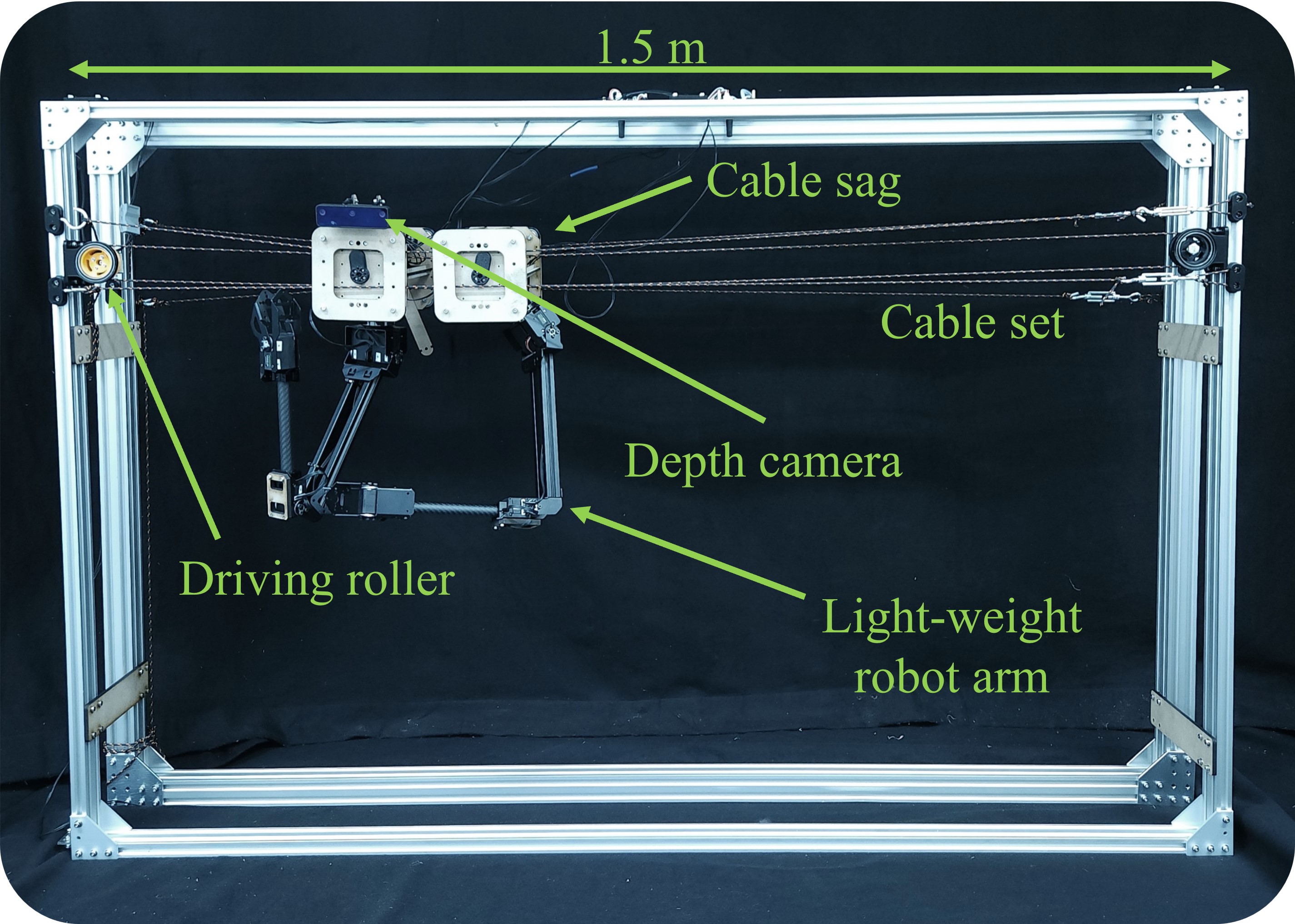
To evaluate the proposed system, we set up a 1.5 m long cable mounted on a fixed aluminum structure, as illustrated in Figure 7. Two CAFEs were deployed and controlled using MATLAB to follow various motions, as shown in Figure 6, with motion data captured using the OptiTrack motion capture system.
The toggle motors (Dynamixel XL430-W250-T), with a stall torque of 1.4 Nm, a speed of 340°/s, a 90° switch angle, and a 0.3-second switching time, were used for the clamping joints. The rolling cable motor (Dynamixel XL430-W250-T) had a stall torque of 1.4 Nm and a movement speed of 120 mm/s. The stiffness of the 3 mm-diameter cables was measured at 18,148.5 N/m, with six cables under approximately 60 kg of pretension each, as shown in Figure 2. The pretension was adjusted using screws, and the value was estimated by calculating the cable angles relative to the horizontal line with a known mass hanging in the middle. A 2 mm-thick thermoplastic elastomer was used as the deformable material in the clamping mechanism (Figure 4). Each CAFE weighed 1.4 kg, with the robotic arm weighing 0.9 kg, and a movable range of 1.3 m. The remaining components were constructed from laser-cut wood and 3D-printed materials.
IV EXPERIMENT RESULTS
This section presents the results of experiments assessing the performance of CAFEs, focusing on the mechanism’s characteristics, accuracy, precision, repeatability, spring-mass model, and scalability. A final demonstration is also given for some agricultural inspired tasks.
(a) Clamp on
(b) Clamp off

(c) Velocity variation on -- axis
IV-A Clamping and switching characteristic of the mechanism
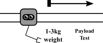
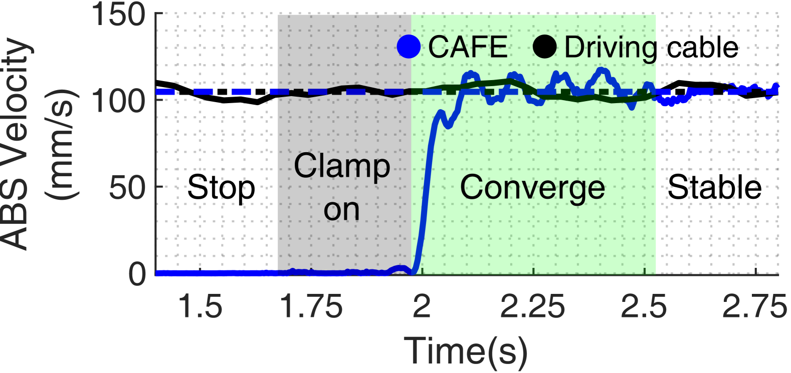
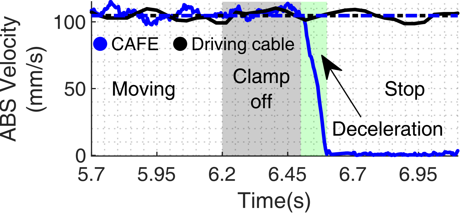
To explore the dynamic changes during state transitions and the influence of one CAFE on another, the motions shown in Figure 6a were executed under varying loads. The roller provided continuous motion at 105 mm/s, controlled by a proportional gain controller. Initially, different numbers of CAFEs remained stationary, then transitioned to a moving state, and finally stopped. As shown in Figures 8 and 8, the CAFE could achieve transition between 0 and 100 mm/s instantly.
The sudden change in load induced an impulsive force on the driving cable leading to damping effects. Consequently, the system exhibited more vibrations and incurred higher position errors with a greater number of CAFEs clamped on simultaneously, especially in vertical () direction.
IV-B Precision of open loop motion
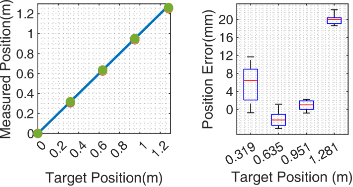
To evaluate the position accuracy and precision of the clamping robot, two sets of trajectories were conducted, as depicted in Figures 6b and 6c. First, the platform aimed to reach predefined target positions spanning to using open-loop control. The desired position was estimated based on the roller’s velocity and measured by the Optitrack system. As shown in Figure 9, position errors accumulated over longer travels. However, the total position error after the traversal was within an acceptable range remained under , which equates to less than .

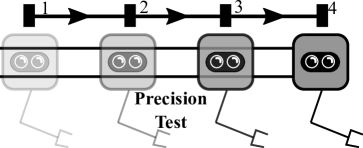
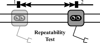
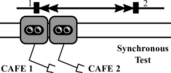
To further assess the platform’s precision, a repeating motion was executed with two platforms synchronously clamping on and off the driven cable, between two positions for 50 repeats, with a fixed cable speed of . This motion sequence involved moving forward, stopping, and then moving backward and stopping. As shown in Figure 10, the error between the target and the measured position accumulated with more repeated motions. However, the relative position error of two CAFEs remains less than mm only, highlighting the advantages of the robot design for task that require synchronous movement.
The results demonstrated that the system achieved significant accuracy and precision, even without close-loop control. However, some accumulated error may arise from mechanical components like cable knots and pulleys, as changes in friction and tension occur when the knot passes through the roller.

IV-C Tension Distribution and System Scalability
To explore the system’s scalability, the cable sag and the number of CAFEs per cable length were estimated using the dynamic model presented in Section II-D. The model was first validated by comparing it with measurement data to ensure accuracy. The experiment setup was experienced the 60kg pretension per cable and resulted in a 2.5mm cable sag due to the close placements of the two CAFEs. As shown in Figure 11, the estimated cable sag closely matched the measured data from Figure 6d. The simulation accurately predicted cable sag during motion, particularly in the vertical displacement of the two CAFEs. Moreoever, since the CAFEs were positioned close to each other, the relative sag error was minimal and did not impact the cooperative tasks.

The dynamic model was then applied to estimate cable sag, cable pretension, and the possible number of deployed CAFEs per cable length for large-scale operations. The results, shown in Figure 12, indicate that for a 10 m cable span, the cable sag for two evenly distributed robots is 13 mm. This suggests that the most sagged robotic arm would need to compensate for a 13 mm vertical displacement to reach the zero horizontal line (the height of the cable anchor). Using the proposed method, application requirements can be estimated based on the known number of robots, robot’s mass, cable length, pretension, and cable stiffness. Additionally, the simplified dynamic model could be use to predict the oscillation mode and cancellation in future developments.
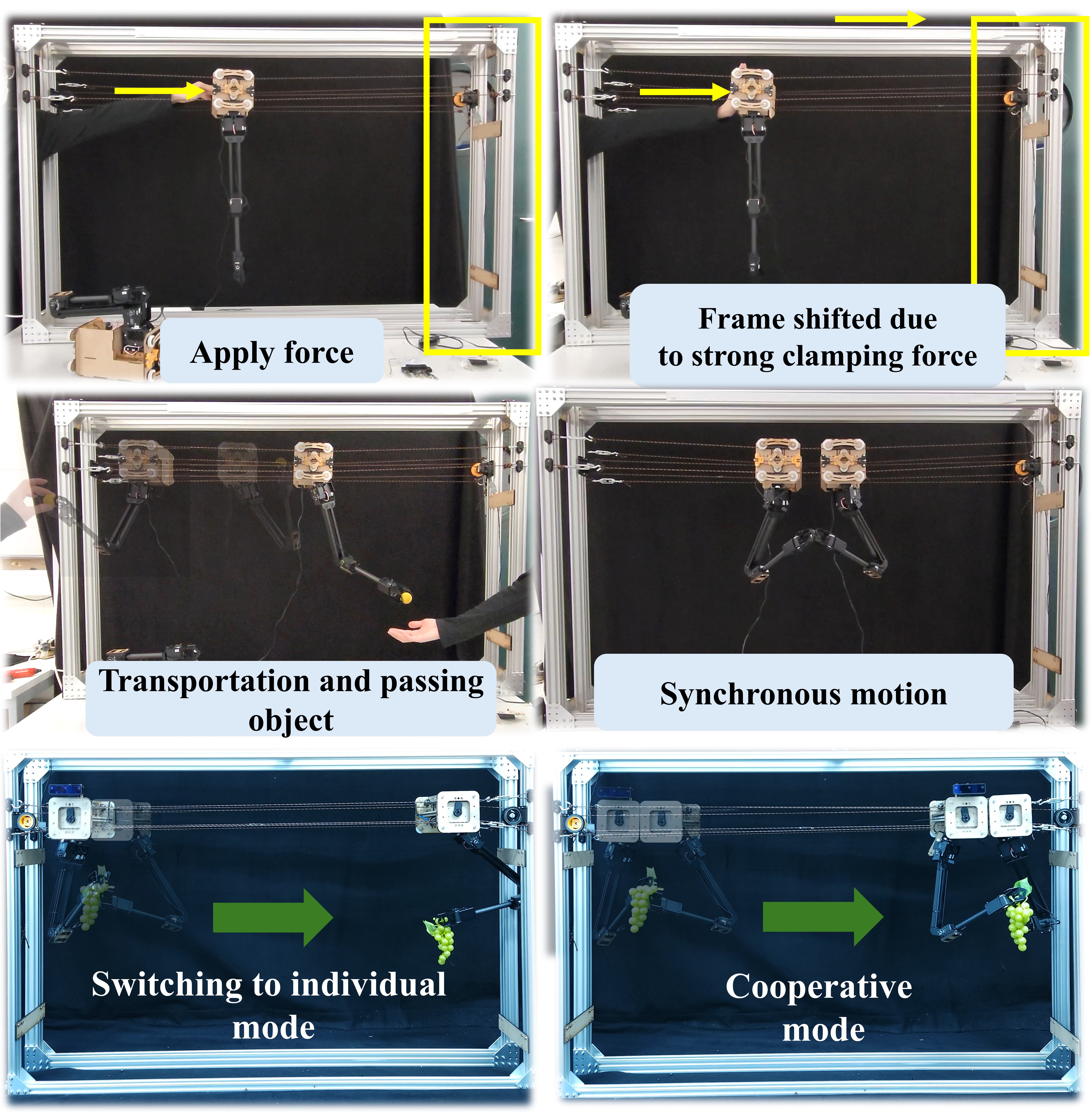
IV-D Demonstration of the System
To demonstrate the collaborative tasks between multiple CAFEs, two prototypes were tasked with performing simple transition and synchronous motions, as shown in Figure 13. The experiment aimed to simulate various operation modes, as depicted in Figure 3. The results indicated that stable and accurate positioning of the floating platforms was crucial, especially during cooperative transitions. Moreover, since the CAFEs were positioned close to each other, the clamping force was tested through demonstrations of transportation and object-passing tasks.
V CONCLUSIONS
The development and testing of the cable-driven Collaborative Agricultural Floating End-effectors (CAFEs) system demonstrate its potential for large-scale agricultural applications by integrating collaborative capabilities, a fast-clamping mechanism, and dynamic scalability, overcoming the limitations of traditional cable-driven robots restricted to a single end-effector. Experiments confirmed high positioning accuracy, stable cooperative motion, and repeatability, while the validated dynamic model for tension distribution and cable sag compensation ensures stability in larger deployments. The results highlight the feasibility of CAFEs for harvesting, monitoring, and object transport, improving operational efficiency. Future work will focus on enhancing control algorithms, optimizing hardware, and refining motion planning to address multi-robot coordination, while further development of anti-oscillation damping will improve system stability, positioning CAFEs as a key technology in agricultural automation.
References
- [1] M. Polzin and J. Hughes, “Automation in steep terrain agriculture: an optimal controller to prevent tipping and slipping of tethered robots on slopes,” Advanced Robotics, vol. 37, no. 15, pp. 987–998, 2023.
- [2] S. Birrell, J. Hughes, J. Y. Cai, and F. Iida, “A field-tested robotic harvesting system for iceberg lettuce,” Journal of Field Robotics, vol. 37, no. 2, pp. 225–245, 2020.
- [3] Y. Xiong, Y. Ge, L. Grimstad, and P. J. From, “An autonomous strawberry-harvesting robot: Design, development, integration, and field evaluation,” Journal of Field Robotics, vol. 37, no. 2, pp. 202–224, 2020.
- [4] D. Turner, A. Lucieer, and C. Watson, “Development of an unmanned aerial vehicle (uav) for hyper resolution vineyard mapping based on visible, multispectral, and thermal imagery,” in Proceedings of 34th International symposium on remote sensing of environment, 2011, p. 4.
- [5] J. Kim, S. Kim, C. Ju, and H. I. Son, “Unmanned aerial vehicles in agriculture: A review of perspective of platform, control, and applications,” Ieee Access, vol. 7, pp. 105 100–105 115, 2019.
- [6] H. Xiang and L. Tian, “Development of a low-cost agricultural remote sensing system based on an autonomous unmanned aerial vehicle (uav),” Biosystems engineering, vol. 108, no. 2, pp. 174–190, 2011.
- [7] J. Torres-Sánchez, J. M. Peña, A. I. de Castro, and F. López-Granados, “Multi-temporal mapping of the vegetation fraction in early-season wheat fields using images from uav,” Computers and Electronics in Agriculture, vol. 103, pp. 104–113, 2014.
- [8] D. Sarri, L. Martelloni, M. Rimediotti, R. Lisci, S. Lombardo, and M. Vieri, “Testing a multi-rotor unmanned aerial vehicle for spray application in high slope terraced vineyard,” Journal of Agricultural Engineering, vol. 50, no. 1, pp. 38–47, 2019.
- [9] L. F. Oliveira, A. P. Moreira, and M. F. Silva, “Advances in agriculture robotics: A state-of-the-art review and challenges ahead,” Robotics, vol. 10, no. 2, p. 52, 2021.
- [10] A. García-Vanegas, M. J. García-Bonilla, M. G. Forero, F. J. Castillo-García, and A. Gonzalez-Rodriguez, “Agrocablebot: Reconfigurable cable-driven parallel robot for greenhouse or urban farming automation,” Robotics, vol. 12, no. 6, p. 165, 2023.
- [11] N. D. Tai and N. T. Thinh, “Design of cable measuring system of a robot spraying pesticides in agricultural farm,” in 2019 International Conference on System Science and Engineering (ICSSE). IEEE, 2019, pp. 577–580.
- [12] P. Prabha, R. S. Vishnu, H. T. Mohan, A. Rajendran, and R. R. Bhavani, “A cable driven parallel robot for nursery farming assistance,” in 2021 IEEE 9th Region 10 Humanitarian Technology Conference (R10-HTC). IEEE, 2021, pp. 1–6.
- [13] M. Tanaka, Y. Seguchi, and S. Shimada, “Kineto-statics of skycam-type wire transport system,” in Proceedings of USA-Japan symposium on flexible automation, Crossing bridges: advances in flexible automation and robotics, 1988, pp. 689–694.
- [14] Y. Wu, H. H. Cheng, A. Fingrut, K. Crolla, Y. Yam, and D. Lau, “Cu-brick cable-driven robot for automated construction of complex brick structures: From simulation to hardware realisation,” in 2018 IEEE International Conference on Simulation, Modeling, and Programming for Autonomous Robots (SIMPAR). IEEE, 2018, pp. 166–173.
- [15] H. H. Cheng and D. Lau, “Ray-based cable and obstacle interference-free workspace for cable-driven parallel robots,” Mechanism and Machine Theory, vol. 172, p. 104782, 2022.
- [16] H. Jamshidifar and A. Khajepour, “Static workspace optimization of aerial cable towed robots with land-fixed winches,” IEEE Transactions on Robotics, vol. 36, no. 5, pp. 1603–1610, 2020.
- [17] H. H. Cheng and D. Lau, “Cable attachment optimization for reconfigurable cable-driven parallel robots based on various workspace conditions,” IEEE Transactions on Robotics, vol. 39, no. 5, pp. 3759–3775, 2023.
- [18] H. Xiong, H. Cao, W. Zeng, J. Huang, X. Diao, W. Lu, and Y. Lou, “Real-time reconfiguration planning for the dynamic control of reconfigurable cable-driven parallel robots,” Journal of Mechanisms and Robotics, vol. 14, no. 6, p. 060913, 2022.
- [19] O. Saber and H. Zohoor, “Workspace analysis of a cable-suspended robot with active/passive cables,” in International Design Engineering Technical Conferences and Computers and Information in Engineering Conference, vol. 55935. American Society of Mechanical Engineers, 2013, p. V06AT07A071.
- [20] A. B. Alp and S. K. Agrawal, “Cable suspended robots: design, planning and control,” in Proceedings 2002 IEEE international conference on robotics and automation (Cat. No. 02CH37292), vol. 4. IEEE, 2002, pp. 4275–4280.
- [21] M. H. Korayem, H. Tourajizadeh, and M. Bamdad, “Dynamic load carrying capacity of flexible cable suspended robot: robust feedback linearization control approach,” Journal of Intelligent & Robotic Systems, vol. 60, pp. 341–363, 2010.
- [22] A. Alikhani and M. Vali, “Modeling and robust control of a new large scale suspended cable-driven robot under input constraint,” in 2011 8th International Conference on Ubiquitous Robots and Ambient Intelligence (URAI). IEEE, 2011, pp. 238–243.