A novel microfluidic method to produce monodisperse micrometer bubbles
Abstract
We present a novel microfluidic method to produce quasi-monodisperse bubbles with diameters from tens to very few microns. A gaseous rivulet flows over the shallow groove printed on a T-junction exit channel. The triple contact line delimiting the rivulet is pinned to the groove edges. The rivulet breaks up into bubbles much smaller than the exit channel. When operating under adequate conditions, the flow transitions toward a singular mode where the rivulet remains quasi-static and emits bubbles smaller than the groove width. This allows the production of bubbles with diameters in the 3-5 m range, which is preferable for relevant therapeutical applications.
I Introduction
The production of monodisperse collections of microbubbles is essential in fields such as medicine (Stride and Edirisinghe, 2008), pharmacology (Ferrara et al., 2007), material science (Suslick and Price, 1999), and the food industry (Zúñiga and Aguilera, 2008). In particular, microbubbles are the most effective contrast agent for medical ultrasound imaging (Frinking et al., 2020). They are used in therapeutic applications, including sonoporation, tumor ablation, and sonothrombolysis, and can be carriers of gas, genes, and oxygen (Unger et al., 2004). Bubbles with diameters below 8 m and low polydispersity indexes must be produced at sufficiently large rates for medical applications.
Two- and three-dimensional co-flow, cross-flow, flow focusing, and T-junction microfluidic devices have been widely used to produce monodisperse collections of microbubbles (Stone et al., 2004; Christopher and Anna, 2007; Anna, 2016). In these cases, the sizes of the fluid passages are similar to or even smaller than the size of the bubble, which constitutes a serious drawback in terms of the high pressures demanded, the limited production rates, and the device clogging.
In an axisymmetric flow-focusing device (Gañán-Calvo and Gordillo, 2001; Gañán-Calvo, 2004; Vega et al., 2014), a coflowing liquid stream crosses an orifice located in front of the gas source. The viscous and pressure forces exerted by that stream collaborate to stretch a gaseous tapering meniscus attached to the feeding capillary, significantly reducing the bubble size at high production rates. However, the bubbles produced with this method are at least tens of microns in diameter when the focusing liquid is water, even if its surface tension is lowered by adding a surfactant. The planar version of the flow-focusing device (Anna et al., 2003; Garstecki et al., 2004; Hettiarachchi et al., 2007; Dollet et al., 2008) has been broadly used to produce monodisperse bubbles for therapeutic applications. In this case, the bubble formation is geometrically controlled, which increases the degree of monodispersity. However, the bubble is commensurate with the channel size.
Castro-Hernández et al. (2011) produced bubbles with sizes below 10 m by applying the flow focusing principle in a 3D device with quadrangular channels 50 m in width. The emitted gaseous thread was stabilized by forcing the pinning of the triple contact line to the boundary between a centered hydrophobic strip and the surrounding hydrophilic surface of one of the walls of the discharge channel. However, the gas ligament was not straight, reducing the monodispersity degree and bubbling frequency (Campo‑Cortés et al., 2016). In addition, the device could be used only for 24 hours to ensure surface hydrophobicity (Castro-Hernández et al., 2011). These limitations were overcome by the device manufactured by Campo‑Cortés et al. (2016), in which the hydrophobic surface was substituted by a groove of around 7.4 m in width and 5 m in depth. The minimum bubble diameter obtained with this device was around 9 m, exceeding the maximum value for therapeutical applications. Herrada et al. (2013) proposed a method in which the gas adhered to a hydrophobic strip printed on the exit channel of a T-junction. The method was studied numerically; it has not been implemented experimentally.
We propose a method to produce microbubbles considering the ideas of Castro-Hernández et al. (2011), Herrada et al. (2013), and Campo‑Cortés et al. (2016). In this method, the two fluids meet in a T-junction. The liquid current forces a micrometer gaseous rivulet to slip over the bottom of the discharge channel, in which a narrow groove was printed to pin the triple contact line. The groove depth was very small to minimize gas flow under the channel surface. As explained in Sec. II, microbubbles are produced from the rivulet breakup following an inertio-capillary mechanism.
Our method verifies two essential conditions commonly demanded in medical applications: (i) bubbles are smaller than 8 m in diameter, and (ii) the polydispersity index (the ratio of the standard deviation to the mean value) is smaller than 10%. Besides, all the device passages are much bigger than the bubbles produced, allowing the device to work safely without clogging and with relatively small applied pressures.
II The proposed method. Bubble ejection modes
Figure 1 shows an image of the microfluidic device used to produce microbubbles. Water is injected at a constant flow rate through the horizontal red tube connected to the quadrangular channel of width . Air is injected at a constant flow rate across the blue tube of diameter , also coupled to the quadrangular channel through a T-junction. A shallow groove of width and depth is printed on the discharge channel bottom.
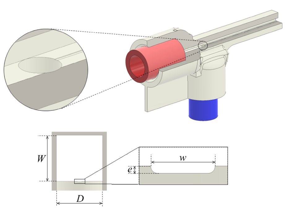
Figure 2 shows the flow modes found in our experiments as the gaseous flow rate decreases for a fixed liquid flow rate . When the gas enters the T-junction, it flows toward the groove driven by the liquid stream. The triple contact lines pins to the groove edges, and a long rivulet moves over the groove. The rivulet cross-section area is practically constant, as occurs in the classical jetting regime. The flow is convectively unstable, which means that capillary waves are convected downstream, allowing the formation of a long, stable gaseous thread. The gas flow rate controls the volume of the rivulet, whose end breaks up into a quasi-monodisperse collection of bubbles due to the capillary instability (Herrada et al., 2015). The size of the bubble is commensurate with that of the rivulet, analogously to what occurs in the classical liquid jetting mode. Hereafter, we will refer to this flow as the “long-rivuletting” (LR) mode.
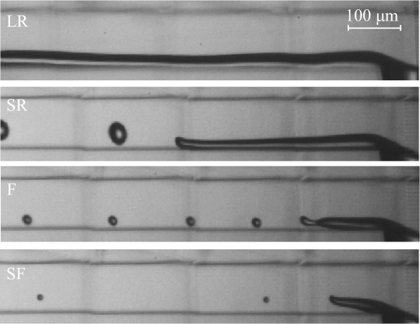
At a given gas flow rate, the rivulet described above sharply shortens. The gas accelerates (the cross-section area decreases) along the gaseous thread. As in the LR mode, the rivulet end breaks up into quasi-monodisperse bubbles with sizes that are commensurate with that of the rivulet. We will refer to this flow as the “short-rivuletting” (SR) mode (Fig. 2). In both the LR and SR modes, the triple contact line in the rivulet front is not pinned but oscillates during the bubble detachment. The difference between the LR and SR modes lies in the character of the instability growing in the rivulet: the rivulet is convectively (absolutely) unstable (Huerre and Monkewitz, 1990) in the LR (SR) mode. A similar distinction can be made, for instance, in the liquid-liquid coflow configuration (Montanero, 2024).
Interestingly, at a critical gas flow rate, , the flow transitions to another regime in which the rivulet tip detaches from the solid surface and ejects tiny bubbles (Fig. 2). Unlike in the LR and SR modes, the front triple contact line is pinned, favoring the energy focusing. We will call this behavior the “focusing” (F) mode.
We decreased the gaseous flow rate slowly and in very small steps to produce the F mode for . At a certain point, the flow autonomously adopted a singular version of this mode characterized by a much smaller gas flow rate (Fig. 2). The rivulet becomes a quasi-static gaseous thread. The liquid current drives the gas to the thread tip. Pressure is built up there due to this hydrodynamic focusing effect, allowing the formation of bubbles with diameters even smaller than the groove width. Hereafter, we will refer to this flow as the “singular-focusing” (SF) mode. The transition from the F to the SF mode seems to be linked to the gas flow rate fluctuations caused by the bubble ejection. The relative magnitude of these fluctuations becomes significant in this mode because takes very small values, and the capillary pressure considerably fluctuates during the ejection of bubbles due to their small size.
The SF mode resembles the microbubbling regime of flow focusing (Gañán-Calvo and Gordillo, 2001), where a quasi-static gaseous meniscus emits tiny bubbles from its tip. As shown in Sec. IV, this mode produces quasi-monodisperse collections of bubbles with diameters well below 8 m, the threshold for medical applications. It is robust (the flow remains stable indefinitely) and highly reproducible. When is decreased below the SF mode value, the gaseous stream does not continuously enter the liquid channel.
The critical role played by the groove in the flow behavior described above must be pointed out. Without that groove, one obtains the classical bubbling and slugging regimes, which give rise to bubbles that are commensurate with or are even larger than the discharge channel size. The groove in our experiments is hydrophilic and much shallower than in previous experiments (Campo‑Cortés et al., 2016), which is key to reducing the bubble size down to 3 m. The sequence of modes described above occurs only within a relatively narrow interval of the liquid flow rate. That interval depends on the microfluidic device’s characteristic lengths and .
III Experimental method
The microfluidic device (Fig. 1) was printed using Nanoscribe Photonic Professional GT2 with the Dip-in Laser Lithography (DiLL) configuration. The 25 objective was dipped into the IP-S resin droplet deposited on an ITO-coated glass substrate. We chose the solid writing strategy. The typical slicing and hatching distances were m and 0.5 m. The part was developed in 25 ml of propylene glycol monomethyl ether acetate (PG-MEA) for 24 h and then cleaned in isopropanol for 2 h. Then, unexposed resin inside the shell was cured for 60 min inside the UV Curing Chamber (XYZprinting). The experiments were conducted with three devices: ( m, m, m), ( m, m, m), and ( m, m, m). The groove depth was m in the three cases.
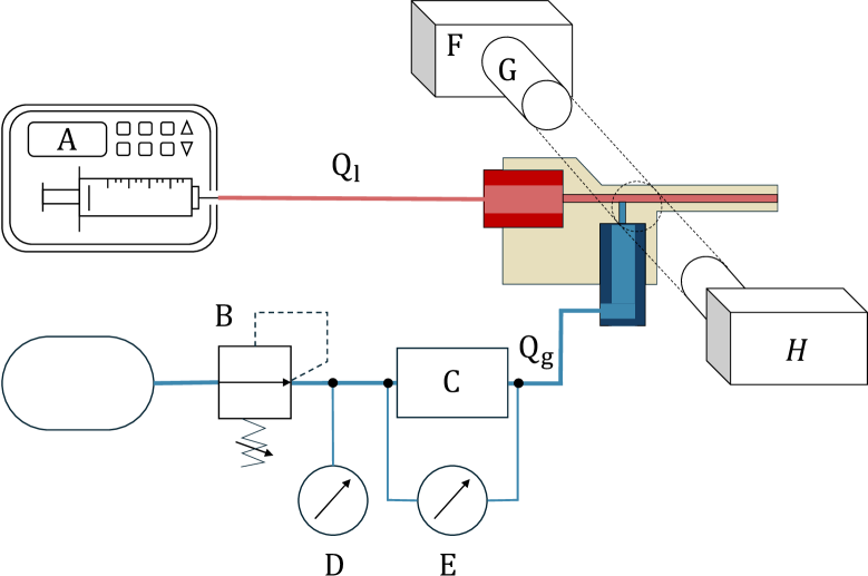
Figure 3 shows the experimental apparatus used in this work. The liquid was injected with a syringe pump (A). The gas pressure was controlled with a high-precision pressure regulating valve (B). Then, the air entered into a hydraulic resistance (C) 155 cm in length and 160 m in inner diameter, which allowed us to fix the gas flow rate and eliminate any mechanical perturbation originating at the pressure valve. The hydraulic resistance supplied the air stream to the microfluidic device. Both the gauge pressure at the tank exit and the pressure drop in the hydraulic resistance were measured with a high-precision manometer (D) and a differential pressure gauge (E), respectively.
Digital images of the rivulet were acquired at up to 20 000 frames per second with an exposure time of 367 ns using an ultra-high-speed CMOS camera (Photron, FASTCAM SA5) (F). The camera was equipped with a set of optical lenses (G), which consisted of a 10 magnification zoom-objective (OPTEM HR) and a system of lenses (OPTEM 70 XL) with variable magnification from 1.5 to 5.25. The magnification obtained was approximately from 0.38 to 1.33 m/pixel. The fluid configuration was illuminated from the back side by cool white light provided by an optical fiber connected to a light source (H). All these elements were mounted on an optical table.
The gas used in the experiments was air ( kg/m3, Pss), while the liquids were water ( kg/m3, mPas) and distilled water with Tween 80 at the concentration 2% (w/v) (Castro-Hernández et al., 2011). The density and viscosity of the Tween 80 aqueous solution were practically the same as those of water, while the surface tension of the gas-liquid interface decreased from mN/m to 39 mN/m.
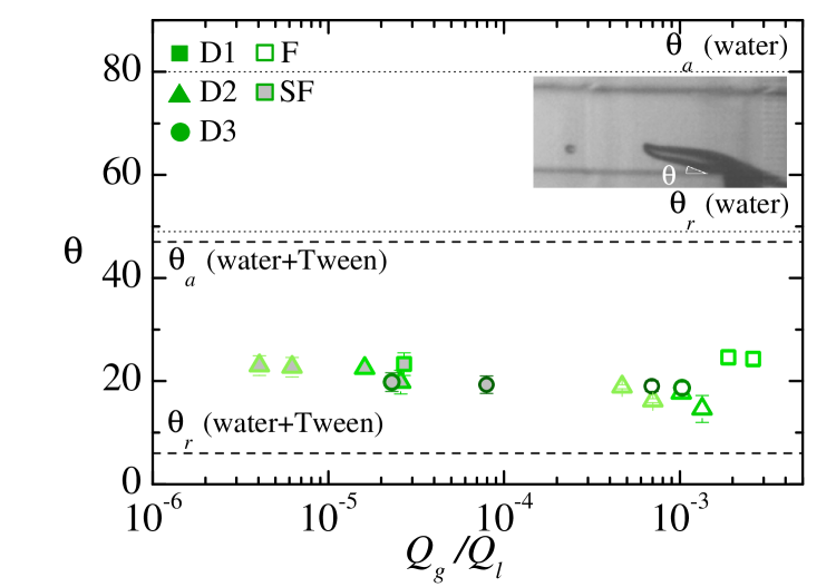
The advancing and receding contact angles of the working liquids on the device surface were measured with the sessile drop method (Korhonen et al., 2013). The values for water were and , while the values for the Tween 80 aqueous solution were and .
The experimental procedure was as follows. The device was carefully cleaned with isopropanol. Then, we fixed the liquid flow rate and the gas flow rate . The gas flow rate was sufficiently high to produce the SR mode. Then, was decreased while keeping constant. A video of the bubble ejection was recorded for each pair of values . The experiment was repeated for several values of . The bubble diameter and ejection frequency were measured from the images. The gas flow rate at the discharge channel was obtained as . We did not analyze the LR mode because the rivulet did not break up into bubbles in many of the experimental realizations.
IV Results
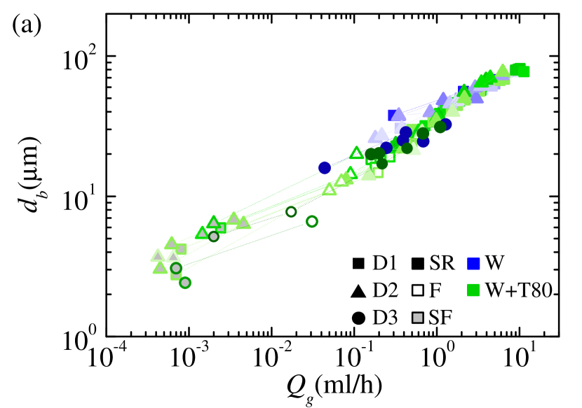
Figure 4a shows the bubble diameter for all the experimental realizations. The transition from the SR to the F mode allowed us to reduce the bubble diameter. The F mode remained stable for smaller values of when was decreased for a fixed value of . An extra stabilization effect was achieved by decreasing as well. Bubbles with diameters in the 6-15 m range were produced in the F mode for m. When the flow adopted the SF mode, the bubble diameter considerably decreased. Microbubbles with diameters smaller than 3 m were produced at frequencies larger than 30 kHz (Fig. 4b) with a high monodispersity degree (Fig. 5) in this mode. This diameter is two orders of magnitude smaller than the channel width. The SF mode was found in the three devices used in our experiments.

For a fixed geometry, the parameters involved in the problem are the width of the discharge channel, the gas density in the T-junction, the liquid density , the gas viscosity , the liquid viscosity , the surface tension , the gas flow rate , and the liquid flow rate . Five dimensionless numbers can be formed with these parameters: the gas and viscosity ratios, and , the Reynolds number Re, the Weber number We, and the flow rate ratio . The gas and viscosity ratios were fixed in our experiments (except for the small variations of due to its dependency on the gas injection pressure). The values of the Reynolds number lie in the interval . As shown below, Rel and Wel are not expected to affect the bubble diameter.
Our experimental results can be rationalized in terms of the scaling analysis proposed by Castro-Hernández et al. (2011). Assuming that the flow along the gas rivulet is developed, can be calculated as
| (1) |
where is a constant, is a rivulet effective diameter, is the gas pressure gradient in the channel direction , and we have neglected the gas flow rate due to the Couette-type flow driven by the liquid current.
Suppose the rivulet cross-section area is approximately constant. Therefore, the capillary pressure does not significantly change along the rivulet, implying that , where is the liquid pressure gradient in the channel direction, is a constant, and is the liquid mean velocity. Then, one obtains
| (2) |
In the SR and F modes, the pressure variations produced by the bubble ejection are not expected to produce significant variations in the flow rate transported by the rivulet. Under this condition, the bubble ejection frequency scales as (Rodríguez-Rodríguez et al., 2015). Therefore,
| (3) |
Equations (2) and (3) lead to (Castro-Hernández et al., 2011)
| (4) |
Equation (4) predicts that the flow rate ratio essentially controls the dimensionless bubble diameter. The viscosity ratio (the gas viscosity) plays a secondary role. The effect of the Reynolds number and Weber number (the surface tension) is negligible.
Campo‑Cortés et al. (2016) assumed that remained practically constant in their experiments with a groove; i.e., did not significantly depend on the flow rate ratio . In this case,
| (5) |
In the experiments of Campo‑Cortés et al. (2016), the rivulet effective diameter was essentially determined by the groove width . The groove in those experiments was much deeper than in our devices. For this reason, the condition is not expected to hold in all our experimental realizations.
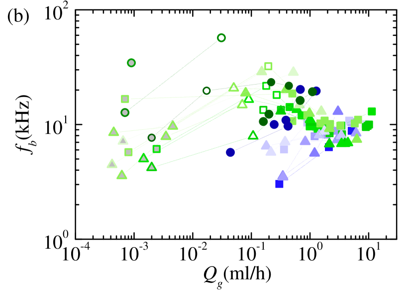
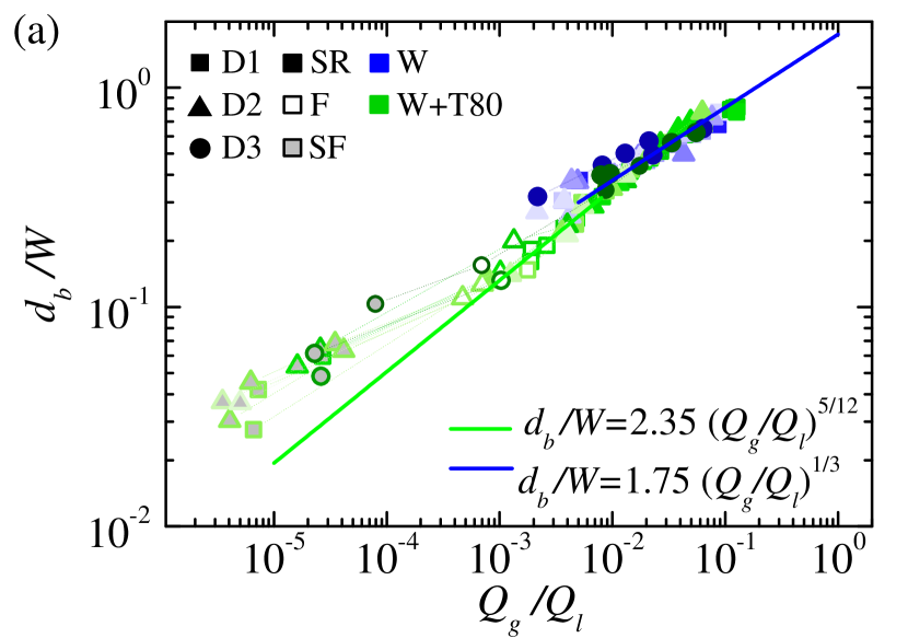
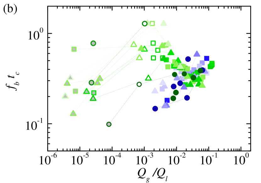
Figure 6a shows the bubble diameter as a function of the flow rate ratio in our experiments. The figure shows results obtained for and 0.1, with and without surfactant. The experimental data for the SR mode satisfactorily agree with the scaling law (5), which indicates that is approximately constant in those experiments. The scaling law (4) approximately holds in the F mode, which suggests that decreases with in this mode [Eq. (2)]. The bubble diameter for exceeds the prediction of the scaling law (4) because of the variations in the gas flow rate during the bubble ejection (Rodríguez-Rodríguez et al., 2015). As a result, the scaling law (5) reasonably agrees with the experimental data over the whole range of . The narrow intervals of and in our experiments explain the relatively small variations of the bubble ejection frequency (Fig. 6b).
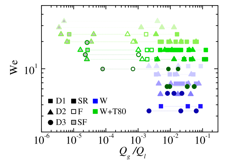
The F and especially the SF mode allowed us to produce monodisperse bubbles that can be useful in medical applications. Figure 7 shows the stability map in the parameter plane (, We), indicating the region where those modes were obtained. The results suggest that there are two requisites to obtain the F and SF modes: (i) the flow rate ratio (the gas flow rate) must be sufficiently small, and (ii) the Weber number must be sufficiently large (the surface tension must be sufficiently small). When the gas flow rate is small enough, the momentum transferred by the liquid current builds up pressure in the rivulet tip. This pressure overcomes the capillary pressure, provided that the surface tension is sufficiently small (the Weber number is sufficiently large). This is achieved by adding the surfactant. There is an additional condition: the values of the receding and advancing contact angles must be such that the triple contact line can pin to the channel surface (. This is also achieved by adding the surfactant (Fig. 8).
V Concluding remarks
We have developed a T-junction-based device capable of producing quasi-monodisperse bubbles much smaller than any of its dimensions. The device relies on the pinning of the lateral three-phase lines delimiting a rivulet. This is achieved due to a groove in the exit channel, as in the flow focusing method proposed by Campo‑Cortés et al. (2016). However, when operating under adequate conditions, our device can produce bubbles with diameters even smaller than the groove width.
The new device can produce bubbles smaller than red blood cells (8 m in diameter), making them suitable for ultrasound contrast agents. In particular, it is possible to produce quasi-monodisperse bubbles approximately 3-5 m in diameter, which are preferable for some therapeutical applications because they are resonant to ultrasound frequencies used for therapy Frinking et al. (2020).
The major drawback of the proposed method is probably the relatively small bubble production frequency (of the order of tens of kHz), a characteristic inherent to the T-junction geometry. The flow-focusing (cross-flow) configuration may operate with larger liquid velocities (applied pressures) and smaller effective rivulet diameters, which may overcome this limitation.
Two-photon polymerization allows one to optimize the flow geometry, leading to a new generation of microfluidic devices for microbubble production that satisfy the stringent conditions demanded in many applications.
Acknowledgement
This work was financially supported by the Spanish Ministry of Science, Innovation and Universities (grant no. PID2022-140951OB-C22/AEI/10.13039/501100011033/FEDER, UE).
References
- Stride and Edirisinghe (2008) E. Stride and M. Edirisinghe, “Novel microbubble preparation technologies,” Soft Matter 4, 2350–2359 (2008).
- Ferrara et al. (2007) K. Ferrara, R. Pollard, and M. Borden, “Ultrasound microbubble contrast agents: fundamentals and application to gene and drug delivery,” Annu. Rev. Biomed. Eng. 9, 415–447 (2007).
- Suslick and Price (1999) K. S. Suslick and G. J. Price, “Application of ultrasound to materials chemistry,” Annu. Rev. Mater. Sci. 29, 295–326. (1999).
- Zúñiga and Aguilera (2008) R. Zúñiga and J. Aguilera, “Aerated food gels: fabrication and potential applications,” Trends Food Sci. Technol. 19, 176–187 (2008).
- Frinking et al. (2020) P. Frinking, T. Segers, Y. Luan, and F. Tranquart, “Three decades of ultrasound contrast agents: A review of the past, present and future improvements,” Ultrasound Med. Biol. 46, 892–908 (2020).
- Unger et al. (2004) E. Unger, T. Porter, W. Culp, R. Labella, T. Matsunaga, and R. Zutshia, “Therapeutic applications of lipid-coated microbubbles,” Adv. Drug Deliv. Rev. 56, 1291–1314 (2004).
- Stone et al. (2004) H. A. Stone, A.D. Stroock, and A. Ajdari, “Engineering flows in small devices: Microfluidics toward a lab-on-a-chip,” Annu. Rev. Fluid Mech. 36, 381–411 (2004).
- Christopher and Anna (2007) G. F. Christopher and S. L. Anna, “Microfluidic methods for generating continuous droplet streams,” J. Phys. D: Appl. Phys. 40, R319–R336 (2007).
- Anna (2016) S. L. Anna, “Droplets and bubbles in microfluidic devices,” Annu. Rev. Fluid Mech. 48, 285–309 (2016).
- Gañán-Calvo and Gordillo (2001) A. M. Gañán-Calvo and J. M. Gordillo, “Perfectly monodisperse microbubbling by capillary flow focusing,” Phys. Rev. Lett. 87, 274501 (2001).
- Gañán-Calvo (2004) A. M. Gañán-Calvo, “Perfectly monodisperse microbubbling by capillary flow focusing: An alternate physical description and universal scaling,” Phys. Rev. E 69, 027301 (2004).
- Vega et al. (2014) E. J. Vega, A. J. Acero, J. M. Montanero, M. A. Herrada, and A. M. Gañán-Calvo, “Production of microbubbles from axisymmetric flow focusing in the jetting regime for moderate Reynolds numbers,” Phys. Rev. E 89, 063012 (2014).
- Anna et al. (2003) S. L. Anna, N. Bontoux, and H. A. Stone, “Formation of dispersions using flow focusing in microchannels,” Appl. Phys. Lett. 82, 364–366 (2003).
- Garstecki et al. (2004) P. Garstecki, I. Gitlin, W. DiLuzio, G. M. Whitesides, E. Kumacheva, and H. A. Stone, “Formation of monodisperse bubbles in a microfluidic flow-focusing device,” Appl. Phys. Lett. 85, 2649–2651 (2004).
- Hettiarachchi et al. (2007) K. Hettiarachchi, E. Talu, M. L. Longo, P. A. Daytonc, and A. P. Lee, “On-chip generation of microbubbles as a practical technology for manufacturing contrast agents for ultrasonic imaging,” Lab Chip 7, 463–468 (2007).
- Dollet et al. (2008) B. Dollet, W. van Hoeve, J.-P. Raven, P. Marmottant, and M. Versluis, “Role of the channel geometry on the bubble pinch-off in flow-focusing devices,” Phys. Rev. Lett. 100, 034504 (2008).
- Castro-Hernández et al. (2011) E. Castro-Hernández, W. van Hoeve, D. Lohse, and J. M. Gordillo, “Microbubble generation in a co-flow device operated in a new regime,” Lab Chip 11, 2023–2029 (2011).
- Campo‑Cortés et al. (2016) F. Campo‑Cortés, G. Riboux1, and J. M. Gordillo, “The effect of contact line pinning favors the mass production of monodisperse microbubbles,” Microfluid Nanofluid 20, 21 (2016).
- Herrada et al. (2013) M. A. Herrada, A. M. Gañán-Calvo, and J. M. Montanero, “Theoretical investigation of a technique to produce microbubbles by a microfluidic T-junction,” Phys. Rev. E 88, 033027 (2013).
- Herrada et al. (2015) M. A. Herrada, A. S. Mohamed, J. M. Montanero, and A. M. Gañán-Calvo, “Stability of a rivulet flowing in a microchannel,” Int. J. Multiphase Flow 69, 1–7 (2015).
- Huerre and Monkewitz (1990) P. Huerre and P. A. Monkewitz, “Local and global instabilites in spatially developing flows,” Annu. Rev. Fluid Mech. 22, 473–537 (1990).
- Montanero (2024) J. M. Montanero, Tip Streaming of Simple and Complex Fluids (Springer Nature, Switzerland, 2024).
- Korhonen et al. (2013) J. T. Korhonen, T. Huhtamaki, O. Ikkala, and R. H. A. Ras, “Reliable measurement of the receding contact angle,” Langmuir 29, 3858–3863 (2013).
- Rodríguez-Rodríguez et al. (2015) J. Rodríguez-Rodríguez, A. Sevilla, C. Martínez-Bazán, and J. M. Gordillo, “Generation of microbubbles with applications to industry and medicine,” Annu. Rev. Fluid Mech. 47, 405–429 (2015).