HAIL: An Efficient Iterative Algorithm for Qubit Mapping via Layer-Weight Assignment and Search Space Reduction
Abstract.
Current quantum devices only support interactions between physical qubits and a limited number of neighboring qubits, preventing quantum circuits from being executed directly on the devices. To execute the circuit, SWAP gates must be inserted to adjust the mapping relationships between qubits, which consequently increases runtime and error rates in quantum circuits. To address these challenges, this paper proposes HAIL, an efficient iterative qubit mapping algorithm to minimize additional SWAP gates. First, a layer-weight assignment method integrated with the subgraph isomorphism algorithm is introduced to establish an initial mapping. Next, we propose a SWAP sequence search combined with the post-processing function to identify the optimal SWAP sequences. Finally, the qubit mapping algorithm is refined through iterative forward and backward traversals to further reduce the number of SWAP gates. Experimental results on the IBM Q20 architecture and various benchmarks demonstrate that HAIL-3 reduces the number of additional gates inserted in the by 20.62% compared to state-of-the-art algorithms. Additionally, we present a partially extended strategy based on HAIL to reduce the sequence search space, with experiments on the sparsely connected Google Sycamore architecture showing a reduction in both algorithm runtime and additional SWAP gates.
1. Introduction
In recent years, quantum computing has emerged as a leading post-Moore’s Law technology, attracting significant attention from researchers due to its powerful parallel processing capabilities. The use of quantum computers to simulate quantum systems, initially proposed by Feynman(feynman2018simulating, ) in 1982, has driven significant advancements in the field. Examples of such progress include Shor’s algorithm for factoring (shor1994algorithms, ), Grover’s search algorithm (grover1996fast, ), and Harrow’s quantum linear systems algorithm (harrow2009quantum, ). In addition to the development of quantum algorithms(li2025efficient, ; song2024quantum, ), quantum hardware has also undergone significant improvements. Recent milestones include the development of quantum chips with 70-100 qubits across diverse quantum technologies such as superconducting, neutral atoms, ion traps, and photonics. This progress culminated in 2023 with the launch of IBM’s Condor(Condor2023ibm, ) quantum processor, featuring 1121 qubits and significantly advancing the practical application of quantum computing.
Despite the remarkable progress in quantum computing, achieving large-scale fault-tolerant quantum computing still faces significant challenges such as limited qubit count and inadequate device connectivity. When executing quantum algorithms on real quantum devices, the connectivity of the physical qubits must be considered, as prevailing quantum architectures support multi-qubit gates only between interconnected qubits. Therefore, it is essential to first establish a mapping between the logical qubits and the physical qubits of the quantum device. When a multi-qubit gate does not satisfy the current mapping relationship, SWAP gates must be inserted to adjust the mapping relationship and make non-adjacent qubits adjacent, enabling the execution of circuits while maintaining functional equivalence between physical and logical circuits. However, this qubit mapping process introduces additional gates, increasing both gate count and circuit depth (sun2023asymptotically, ), which can adversely affect quantum algorithm performance. So the primary goal of qubit mapping is to minimize the number of SWAP gates.
The qubit mapping problem, formally recognized as NP-complete (botea2018complexity, ; NPsiraichi2018qubit, ), poses significant challenges. Various methods(ge2024quantumcircuitsynthesiscompilation, ) have been employed to address this issue, including mathematical programming, machine learning, and heuristic algorithms. Mathematical programming techniques involve converting mapping problems into integer programming problems (shafaei2014qubit, ; nannicini2022optimal, ; bhattacharjee2017depth, ; bhattacharjee2019muqut, ), satisfiability (SAT) problems (tan2021optimal, ; murali2019noise, ; lye2015determining, ; wille2019mapping, ; molavi2022qubit, ; lin2023scalable, ), and then solving them with different kinds of advanced solver, such as the SMT solver (Satisfiability Modulo Theories) and the SAT solver. However, these methods are often limited to smaller problems due to their high time complexity. On the other hand, machine learning approaches for qubit mapping problems have emerged with the advancement of artificial intelligence technologies(zhou2020monte, ; sinha2022qubit, ; pozzi2022using, ; li2024deep, ; fan2022optimizing, ; zhou2022supervised, ; paler2023machine, ), including Monte Carlo Tree Search (zhou2020monte, ), reinforcement learning (pozzi2022using, ), and neural networks (zhou2022supervised, ), for decision making. However, these methods face challenges such as extensive data requirements, high computational costs, and limited interpretability, which hinder their widespread adoption.
In contrast, heuristic algorithms offer excellent scalability, efficiently solving mapping problems involving tens of qubits and thousands of quantum gates in a relatively short time. These algorithms use experience-based rules to optimize qubit placement and SWAP gate insertion for near-optimal SWAP costs. Numerous heuristic algorithms for qubit mapping have been developed(matsuo2012changing, ; zulehner2018efficient, ; li2019tackling, ; ash2019qure, ; niu2020hardware, ; lao20222qan, ; li2023timing, ; li2020qubit, ; zhu2021iterated, ; qian2023method, ; jiang2021quantum, ; datta2023improved, ; chang2021mapping, ; ovide2023mapping, ; liu2023tackling, ; zhu2020dynamic, ; huang2024efficient, ). For example, Zulehner et al. (zulehner2018efficient, ) first introduced the A* search algorithm, but the search space grows exponentially with depth, which can potentially result in high complexity. In response, Li et al. (li2019tackling, ) proposed SABRE, a novel bidirectional search algorithm that significantly reduces both time complexity and the number of additional SWAP gates compared to the A* algorithm. Additionally, Li et al. (li2020qubit, ) employed subgraph isomorphism algorithms for initial mapping, effectively identifying SWAP-free mappings. However, they use the number of gates between qubits as weights for isomorphism discrimination, which may inadequately captures circuit details. To improve initial mappings, iterative methods have been introduced. These methods refine mappings by exploring their neighborhood through repeated circuit executions. Zhu et al. (zhu2021iterated, ) developed an iterative algorithm using bidirectional searches and shuffling perturbations to reduce SWAP gates. But it requires multiple iterations, which may increase computational demands. Qian et al. (qian2023method, ) proposed a time-weighted method where gate weights decrease progressively, addressing uniform weight issues. However, it does not fully account for parallel gate weights, which may potentially limiting its effectiveness. Despite advances, challenges like neglecting parallel gate weights, high iteration counts, and long runtime remain. Research by Tan (tan2020optimality, ) reveals significant performance gaps in QUEKO benchmarks, indicating a need for further improvements in heuristic qubit mapping algorithms.
In this paper, we propose HAIL, an iterative optimization-based heuristic algorithm with the aim of minimizing the additional SWAP gates in the qubit mapping problem. The algorithm begins with the introduction of subgraph isomorphism algorithm and a completion algorithm with layer-weight assignment to partition the circuit and map it into a coupling structure graph. To address limitations of the subgraph isomorphism algorithm, a mapping completion approach is employed to enable qubit insertion around placed qubits. After establishing a complete initial mapping, we apply a sequence search method for SWAP gates, prioritizing sequences with the highest average executable CNOT count, and refine this selection with a loss function based on distance and layer-weight. We then introduce a simplified iterative framework using forward-backward techniques for optimizing the mapping. Experimental results show that HAIL-3 outperforms state-of-the-art methods, including SABRE, ILS, and TWP, achieving a 20.62% reduction in additional SWAP gates on the IBM Q20 for the benchmark. When HAIL is integrated with a search space reduction strategy, comparative experiments across various benchmarks and architectures demonstrate reductions in both runtime and additional gates, confirming its scalability and efficiency.
The rest of this paper is organized as follows. Section 2 introduces the background of quantum computing, followed by a detailed description of the proposed algorithm in Section 3. In Section 4, experiments are carried out on the IBM Q20 and Google Sycamore architectures, with a comprehensive analysis of the results performed. Finally, the whole paper is summarized.
2. Background
This section aims to provide a concise introduction to the fundamentals of quantum computing, enabling a better understanding of the challenges surrounding qubit mapping and the proposed methodologies.
2.1. Quantum Gates and Quantum Circuits
Qubit is the fundamental unit of quantum computing. Unlike classical bits, which can only be in states of 0 or 1, qubits can exist in superpositions of these states due to quantum mechanics. In quantum computing, a qubit’s state can be represented as , where and are the basic states, and and are complex numbers satisfying the normalization condition .
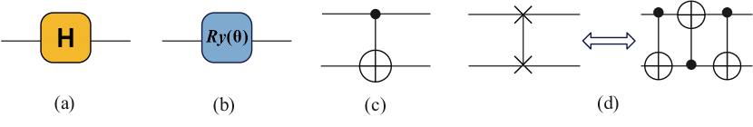
Quantum gates typically act on qubits, and a combination of single-qubit gates and CNOT gates can generally achieve arbitrary unitary gates. Therefore, these two types of quantum gates are introduced primarily. In Fig. 1, some representative quantum gates are illustrated. The gate is extensively used for creating quantum superposition states. The gate, a single-qubit gate rotating around the Y-axis, is prominent in variational quantum algorithms. The CNOT gate, denoted as , alters the target qubit’s state based on the control qubit’s state. If the control qubit is , the target qubit undergoes an gate. The SWAP gate facilitates the exchange of states between two qubits, transforming to . Additionally, a SWAP gate can be decomposed into three CNOT gates, which is crucial in qubit mapping problems.
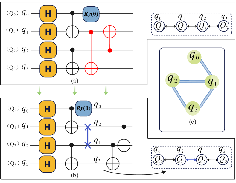
A quantum circuit acts as a formal representation of a quantum algorithm or program, delineated by a series of quantum gates, as demonstrated in Fig. 2(a). This circuit comprises five single-qubit gates ( gate and gate) and four two-qubit gates (CNOT gate). In this paper, such quantum circuits are called logical circuits, denoted by the notation , where represents logical qubits, and denotes the set of all gates in the circuit. Fig. 2(b) shows the quantum circuit after being adjusted for execution in the given quantum architecture, where a SWAP gate is inserted. Since gate permutation or cancellation operations between gates are not performed in the quantum circuit in our paper, single-qubit gates do not affect the outcome of qubit mapping. Thus, the qubit mapping problem can be simplified to only consider two-qubit gates.
2.2. Qubit Interaction Graph and Quantum Hardware Architecture
Once a quantum logical circuit is obtained, a qubit Interaction Graph () can be defined to represent the connections of the logical qubits. The is an undirected graph where nodes represent the qubits in . An edge is formed between two nodes and if there is a correlated two-qubit gate between them, which plays a crucial role in subgraph isomorphism matching. Specifically, Fig. 2(c) illustrates the for the quantum circuit shown in Fig. 2(a), consisting of four nodes and four edges.
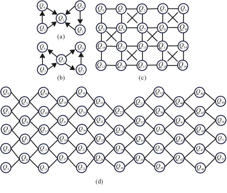
The quantum hardware architecture is represented as , where denotes the nodes and denotes the edges. To provide an overview of quantum hardware architectures, Fig. 3 illustrates several architectures from IBM and Google. Despite advancements such as the Condor quantum processor, current architectures are still constrained by connectivity limitations. Among these architectures, the IBM Q20 is notable for its dense bidirectional connectivity and is widely used.
2.3. Initial Qubit Mapping and Routing Problem
The quantum circuit mapping problem is primarily divided into the initial qubit mapping and qubit routing problems, with the assumption that the input quantum circuit is denoted as and the given quantum device as .
First, the initial qubit mapping problem refers to the one-to-one correspondence between logical qubits and physical qubits (e.g., ). This process typically involves various approaches such as random mapping, naive mapping, and optimization-based techniques. An example of a simple mapping is shown in Fig. 2(a), where the mapping is represented as . Under this mapping, the gate marked in red cannot be executed because the mapped nodes are not directly connected.
The routing problem is defined as follows: during the execution of the circuit, if a gate cannot be executed due to the current mapping and gate dependency constraints, SWAP gates must be inserted to transform the mapping, resulting in a new mapping . As shown in Fig. 2(b), the insertion of SWAP gates allows the remaining two CNOT gates to be executed. However, this process introduces additional SWAP gate operations, and thus, the primary optimization goal of quantum circuit mapping is to minimize the number of additional SWAP gates inserted.
3. Method
This section provides an introduction to the proposed method for minimizing the additional insertion of SWAP gates. First, a layer-weighted subgraph isomorphism approach and a novel mapping completion method are presented to establish the initial mapping. Subsequently, a SWAP sequence search method is introduced to address the selection of SWAP gates. Finally, the approach incorporates a simplified iterative optimization framework, which significantly enhances the overall effectiveness of the mapping algorithm.
3.1. Initial Mapping
To address the mapping problem, we divided the entire algorithm into two parts, ultimately generating a reasonable initial mapping to reduce the number of subsequent SWAP gate insertions.
3.1.1. Layer-Weighted Isomorphism Mapping Algorithm
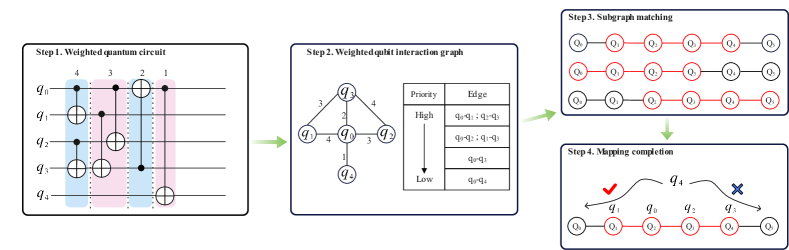
We are addressing the connectivity issue and have proposed a layer-weight-based method to fully consider the priority of each gate in the circuit through weight assignment, thereby enabling the execution of more CNOT gates at the front of the circuit and reducing the distance between subsequent gates. This method prioritizes quantum gates located at the front of the circuit, ensuring that they have the highest priority. When multiple gates can be executed simultaneously, they are assigned equal weights, making this weight-based layer approach intuitive and rational. The process is detailed in Steps 1 to 3 in Fig. 4. Initially, the circuit is partitioned, ensuring qubits of any two gates in the same layer do not intersect. Then, for each gate , a corresponding weight is assigned using the following weight function:
| (1) |
where represents the circuit depth after the partition of , and represents the layer number where is located.
Then for any given quantum circuit , after denoting to describe the interactions between qubits in the quantum circuit, we use the layer weight (Eq. 1) to assign a value for each gate in the circuit. In , the weight on each edge is the sum of the weights of the corresponding gates, described by the following formula:
| (2) |
where the criterion implies that both qubits and should be involved in the quantum gate , and represents the edge between the two qubits.
After obtaining the with layer-weight assignment, we utilize the VF2 algorithm (1323804, ), a widely used subgraph isomorphic matching algorithm, to maximize the embedding of edges contained in the into the , thus establishing the correspondence between logical qubits and physical qubits. The initial mapping algorithm is described in Algorithm 1. It takes the logical circuit and a specific hardware architecture as inputs. Initially, the logical circuit is partitioned into layers using the function , which determines the depth of the quantum circuit and assigns each gate to its corresponding layer number. Subsequently, the function converts the logical circuit into a qubit interaction graph (). Each gate is then assigned a weight based on its layer position, and these weights are associated with the edges in . Finally, the edges in are sorted based on their weights in descending order, establishing the priority of each edge. Upon successive addition of each edge to to form the graph , which represents the current maximum subgraph matched. If the addition of an edge makes isomorphic to any subgraph in the hardware architecture , then the edge is included in . This process continues until all edges have been traversed.
For example, in step 3 of Fig. 4, we begin by incorporating the edge set to form the graph , based on the priority of edges obtained in step 2, because these two edges can be embedded into the architecture graph. is then added to , and it remains compatible with the architecture graph. For the subsequent edges , , and , adding any of these to does not fit within the architecture graph, so these edges are excluded from . Ultimately, a graph is obtained that includes the edges , which can be embedded in , while a qubit labeled remains unmapped. The red parts illustrate the feasible mapping relationships, one of which is represented by the mapping . This mapping enables the execution of three CNOT gates, whereas the naive mapping can only execute two, thus making the proposed approach more efficient.
3.1.2. Mapping Completion Algorithm
Since subgraph isomorphism may result in discrete unmapped qubits during the initial mapping process, we introduce a completion algorithm to address this issue. The primary objective is to map the unmapped qubits to the most suitable free nodes, thereby reducing the distances between gates involving these qubits and subsequently minimizing the number of SWAP gates. As the two most critical attributes of gates are distance and weight, the optimal scenario for circuit execution is to enhance the number of executable gates by reducing the distances for gates with greater weights. In Step 4 of Fig. 4, the mapping completion algorithm serves a discriminative function to determine the optimal positions. The algorithm details are outlined in Algorithm 2.
Considering that a closer placement of qubits leads to a reduction in the distance between the two qubits of the CNOT gates, the candidate nodes refer to the free nodes that are located adjacent to the already deployed nodes. For all logical qubits, if the qubit has not been mapped yet, the corresponding function value is calculated for placing it on each available node, and the position with the maximum function value is identified for . The detailed content of the function is as follows:
| (3) |
where represents an unmapped qubit, is the node in that has been mapped by ’s neighboring logical qubit, and is a previously mentioned free candidate node in . The stands for the diameter of , is the distance between the nodes and , and represents the edge weight between logic qubits corresponding to the nodes and .
The proposed heuristic function effectively accounts for the relationship between the evaluation node positions and their corresponding weights. If the distance between the free node and the already placed node is short, and the weight value between them is high, it indicates that the mapping can execute more CNOT gates. Therefore, selecting the logical qubit and the free node with the highest function value enables a good completion of the current mapping algorithm, and adding this mapping relation to the current mapping completes the update. This process continues iteratively until all logical qubits are mapped to appropriate free nodes. Ultimately, the algorithm returns a final mapping result, where each logical qubit is mapped to a corresponding physical hardware node, completing the mapping process.
For example, as illustrated in step 4 of Fig.4, the placement position for the unallocated qubit is determined using the evaluation function specified in Eq. 3. The function is calculated for two potential mapping positions:
| (4) | |||
| (5) |
These calculations reveal that mapping qubit to results in a higher evaluation score of 3, in contrast to a score of 2 for mapping it to . To optimize the evaluation function and ensure the most effective placement, is chosen as the mapping position for qubit . As a result, the final mapping relationship is expressed as which demonstrates that it is a complete mapping and each logical qubit is assigned a specific position within the architecture graph.
3.2. Intermediate Qubit Routing
The initial mapping obtained above typically fails to meet the requirements for executing all CNOT gates, requiring additional SWAP gates. To tackle this, we divide the proposed qubit routing algorithm into two stages: SWAP sequence selection and post-processing to refine the optimal sequence.
3.2.1. SWAP Sequence Selection
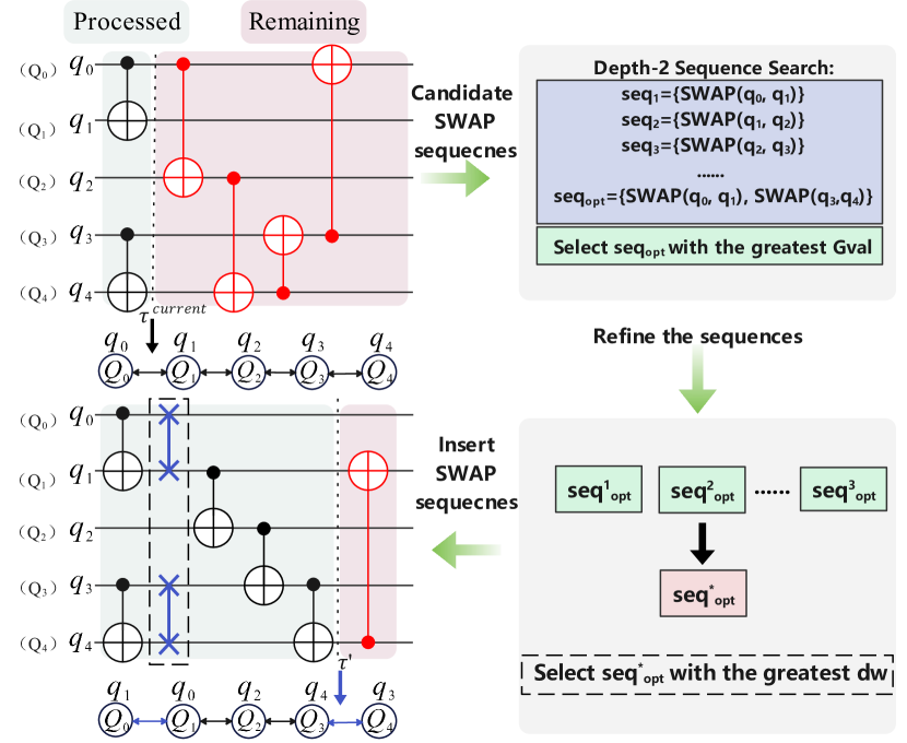
We introduce a method for selecting SWAP sequences to better accommodate the initial mapping algorithm proposed in the previous section. First, we introduce the set where each element represents a SWAP gate that involves at least one qubit from the look-ahead three layers of the currently unexecutable circuit. We also assume that the number of elements in this is . Therefore, for a SWAP sequence of length , it is formulated as , with each . There are a total of possible length swap sequence, and the collection of all such sequences forms . For the SWAP sequence search with depth , the set is defined as , where the number of elements in is . For a quantum device , the total number of candidate SWAP sequences is in the worst case.
For the evaluation of each SWAP sequence, the average number of two-qubit gates executable per SWAP gate is selected as the primary metric. This approach is considered more direct and insightful than a distance-based evaluation between gates. Consequently, the heuristic function is defined as follows, with the optimal sequence chosen to maximize this heuristic function:
| (6) |
where denotes the current mapping, indicates the number of SWAP gates contained in the . represents the mapping relation corresponding to after the insertion of the SWAP gates included in .
Finally, after determining the SWAP sequence corresponding to the maximum function, the SWAP gates in the are inserted sequentially. However, since the calculation may have multiple maximum function values , further judgments are required to determine which SWAP sequence is optimal. This additional processing is conducted in the post-processing stage to make a more reasonable decision. Besides, if a suitable SWAP sequence cannot be found within the set search limit to enable the subsequent gates to be executed, an alternative approach is adopted. The CNOT gate whose corresponding two qubits are closest in the front layer is selected, and then a SWAP gate is applied to reduce the distance between them.This ensures that the routing algorithm runs smoothly, preventing situations where CNOT gates cannot be executed within the specified search depth.
3.2.2. The Post-Processing Stage
This stage aims to address the situation where multiple identical maximum values exist. Given that our primary objective is to execute more gates per SWAP, it is therefore reasonable to treat Eq.6 and this stage separately. Specifically, if two mappings, and (more mappings of the same value are also applicable), have the same value, specifically . Then an evaluation function based on weight and distance is proposed to further assess their merits, thereby improving the routing algorithm. Given that gates in the rear have a relatively small impact on the mapping algorithm, and considering the potentially large number of subsequent gates, a significant amount of additional calculations will be introduced. Therefore, a look-ahead window is set, with its size determined by the hyperparameter . The evaluation function for post-processing is:
| (7) |
where represents the weight of gate , represents the distance of qubit and in the gate under the mapping relationship .
By integrating both weight and distance considerations, this function appropriately assesses the influence of these factors simultaneously. This block resembles the heuristic function Eq. 3 proposed earlier for initial mapping, but with a difference: it primarily focuses on the distance of each gate and its associated weight. Both are effective in completing the corresponding tasks. Algorithm. 3 combines the SWAP sequence selection and post-processing to optimize intermediate qubit routing. It takes inputs such as the logical circuit, the physical hardware architecture, and the generated initial mapping. Initially, it identifies executable gates (EG) based on the current mapping, transferring them from the logical circuit to the physical circuit . The algorithm iterates until all gates in are executed. During each iteration, it calculates the SWAP sequence with the largest and applies post-processing to find the most suitable sequence using the discriminant function . The selected SWAP gates are then inserted into sequentially, and the current mapping is adjusted according to the SWAP sequence using the transformation function. This process continues until all gates are executed and the modified physical circuits and are returned.
To clearly illustrate the entire SWAP sequence insertion process, the schematic diagram of the insertion of the SWAP sequence is shown in Fig. 5. Under the mapping , two CNOT gates can be executed, while four CNOT gates (marked in red) cannot. We choose a Depth-2 sequence search in this example. After applying the heuristic evaluation functions in Eq. (6) and Eq. (7), the optimal SWAP sequence is selected and inserted into the circuit, resulting in the mapping , which enables the execution of the subsequent three CNOT gates.
In general, the intermediate qubit routing algorithm can take into account many factors such as the size of the search space, weight information, and distance between qubits. Compared with many other intermediate qubit routing algorithms, it can comprehensively assess the influence of weight and distance and effectively balance their relationships. This also enables the mapping algorithm to outperform many existing algorithms in terms of overall effectiveness.
3.3. Simplified Iterative Optimization Framework
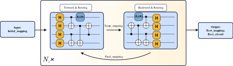
To find the case with the minimum number of SWAP gates, one could repeatedly run the routing algorithm for the entire circuit. However, in a quantum circuit consisting of qubits, there are ! potential initial mappings. Therefore, exhaustively evaluating these mappings to assess their quality incurs a significantly high time complexity. To efficiently alleviate the need for additional SWAP gate insertions in the circuit and enhance initial mappings, we propose a simplified iterative optimization framework, which can effectively mitigate the high complexity problem caused by exhaustive methods through a small number of iterations.
The simplified iterative optimization framework, depicted in Fig. 6, takes the as input, which defines the relationship between logical qubits and physical qubits. It incorporates a common forward-backward traverse technique (li2019tackling, ) to optimize the qubit mapping, where the quantum circuit’s gates are traversed in both forward and backward directions. The process typically begins with a random initial mapping and then refines it using the routing algorithm and its inverse circuit, resulting in a mapping that better aligns with the connectivity requirements of the initial gates. Unlike other algorithms based on this technique, our focus extends beyond initial mapping generation to optimizing circuit mapping results during the iterative process. Compared to the iterative algorithm presented in (zhu2021iterated, ), our algorithm incorporates an effective initial mapping rather than a random one to enhance the comprehensive performance of the algorithm. Additionally, we prioritize the performance of the intermediate qubit routing algorithm, as it is more crucial within the overall qubit mapping algorithm. Thus, we simplify the shuffling perturbations towards optimal mapping, reduce the number of high iterations, and address other relevant aspects during the iteration process, which reduces computational resource requirements.
After completion of the forward-traverse phase of the quantum circuit, the at the end of the circuit is preserved for input into the inverse circuit, then the circuit is processed again by the routing algorithm to execute all the gates. This process ultimately yields . The is then iteratively input back into the initial circuit. Ultimately, our objective is to preserve the best mapping and quantum circuit with the smallest number of additional SWAP gates inserted throughout the iterations. Within the iterative framework, the parameter indicates the number of iterations required for optimization. Importantly, it is crucial to track the circuit execution direction at minimal cost during the iteration process. This is because the case with the minimum number of SWAP gates inserted may occur in the backward-traverse phase, where it is necessary to invert the current circuit to obtain the target quantum circuit.
Complexity Analysis. As for the analysis of the algorithm’s time complexity. In the worst-case scenario, for any given architecture and quantum circuit , if the SWAP sequences have length , there will be possible sequences. The computational complexity of each sequence is linearly related to , and if only one gate is executed each time, there will be a maximum of iterations. The entire process requires iterations. Therefore, the overall time complexity of the iterative framework, including routing, is .
4. Experiments and Evaluation
In this section, we will evaluate the proposed HAIL algorithm and compare its performance with that of other algorithms across various benchmarks and coupling architectures.
Benchmarks. We evaluate the proposed algorithm using publicly available benchmarks, including , which contains 23 quantum circuits categorized by gate count: small ( gates), medium ( gates), and large ( gates). Additionally, we assess the algorithm’s performance across various scenarios using multiple benchmarks (zhou2020monte, ). These benchmarks, limited to 20 qubits, include single-qubit operations (e.g., , , ) and CNOT gates. A detailed description of these benchmarks is provided in Table 1, allowing for a comprehensive evaluation of the algorithm across different circuit scales.
| Benchmark Name /Number of Circuits | Total Number of Gates | Average CNOTs per Circuit |
|---|---|---|
| /23 | 63333 | 1202.609 |
| /114 | 554497 | 2180.289 |
| /170 | 34000 | 200 |
| /173 | 603654 | 1506.295 |
Hardware Architecture. Commonly used quantum architectures, such as the IBM Q20 (Fig. 3(c)) and the Google Sycamore (Fig. 3(d)), were employed to evaluate the algorithm’s adaptability by considering architectures with varying levels of sparsity.
Algorithm Configuration. To distinguish between different SWAP search depths during the routing phase, we defer to the algorithm with a search depth of as HAIL-. The number of iterations is fixed at 5, and each SWAP gate involves at least one qubit from the first three layers of the remaining gates. Additionally, to adjust dynamically, if the remaining gates exceed 4000, is set to , otherwise, it remains at 30.
Experimental Platform. All experiments were conducted on a personal laptop featuring an Intel(R) Core(TM) i5-8300H CPU @ 2.30GHz, paired with 16 GB of DDR4 RAM.
Comparative Algorithms. To validate the effectiveness of the proposed algorithm, we compare it with state-of-the-art algorithms like SABRE(li2019tackling, ), ILS(zhu2021iterated, ), TWP(qian2023method, ). Since TWP is an improvement of FIDLS(li2020qubit, ) and exhibits superior performance, it has been selected for comparison.
| Benchmark | Number of additional CNOT gates | Optimization ratio | |||||||
| Circuit Name | Qubit Num | Gate Num | (li2019tackling, ) | (zhu2021iterated, ) | (qian2023method, ) | (HAIL-3) | |||
| 4mod5_v1_22 | 5 | 21 | 0 | 0 | 0 | 0 | 0.00% | 0.00% | 0.00% |
| mod5mils_65 | 5 | 35 | 0 | 0 | 0 | 0 | 0.00% | 0.00% | 0.00% |
| alu-v0_27 | 5 | 36 | 3 | 3 | 9 | 3 | 0.00% | 0.00% | 66.67% |
| decod24v2_43 | 4 | 52 | 0 | 0 | 0 | 0 | 0.00% | 0.00% | 0.00% |
| 4gt13_92 | 5 | 66 | 0 | 0 | 0 | 0 | 0.00% | 0.00% | 0.00% |
| qft_10 | 10 | 200 | 54 | 27 | 33 | 30 | 44.44% | -11.11% | 9.09% |
| qft_16 | 16 | 512 | 186 | 120 | 117 | 120 | 35.48% | 0.00% | -2.56% |
| ising_model_10 | 10 | 480 | 0 | 0 | 0 | 0 | 0.00% | 0.00% | 0.00% |
| ising_model_13 | 13 | 633 | 0 | 0 | 0 | 0 | 0.00% | 0.00% | 0.00% |
| ising_model_16 | 16 | 786 | 0 | 0 | 0 | 0 | 0.00% | 0.00% | 0.00% |
| rd84_142 | 15 | 343 | 105 | 60 | 66 | 57 | 45.71% | 5.00% | 13.64% |
| sym6_145 | 7 | 3888 | 1272 | 495 | 405 | 369 | 70.99% | 25.45% | 8.89% |
| z4_268 | 11 | 3073 | 1365 | 456 | 363 | 372 | 72.75% | 18.42% | -2.48% |
| radd_250 | 13 | 3213 | 1275 | 579 | 576 | 384 | 69.88% | 33.68% | 33.33% |
| cycle10_2_110 | 12 | 6050 | 2622 | 948 | 969 | 729 | 72.20% | 23.10% | 24.77% |
| adr4_197 | 13 | 3439 | 1614 | 516 | 648 | 381 | 76.39% | 26.16% | 41.20% |
| misex1_241 | 15 | 4813 | 1521 | 492 | 444 | 414 | 72.78% | 15.85% | 6.76% |
| rd73_252 | 10 | 5321 | 2133 | 876 | 732 | 615 | 71.17% | 29.79% | 15.98% |
| square_root_7 | 15 | 7630 | 2598 | 819 | 1017 | 738 | 71.59% | 9.89% | 27.43% |
| co14_215 | 15 | 17936 | 8982 | 2775 | 2658 | 2340 | 73.95% | 15.68% | 11.96% |
| rd84_253 | 12 | 13658 | 6147 | 2484 | 1827 | 1719 | 72.04% | 30.80% | 5.91% |
| sqn_258 | 10 | 10223 | 4344 | 1599 | 1212 | 999 | 77.00% | 37.52% | 17.57% |
| sym9_193 | 11 | 34881 | 16653 | 5562 | 5361 | 3777 | 77.32% | 32.09% | 29.55% |
| Sum | - | - | 50874 | 17811 | 16437 | 13047 | 74.35% | 26.75% | 20.62% |
4.1. Performance Analysis Compared with Some Algorithms on IBM Q20
This experiment was conducted on the IBM Q20 architecture using the benchmark. We can see in Table. 2, the first three columns contain the circuit benchmark information, while the subsequent four columns (, , , ) respectively display the number of CNOT gates inserted by SABRE, ILS, TWP, and our proposed algorithm HAIL-3 into the corresponding circuit. The last three columns show the improvement rate of our algorithm to others. This comparison is calculated by the formula:
| (8) |
From the comparative data, it is evident that the optimization capability of our proposed HAIL-3 algorithm is limited for small-scale circuits, as the competing algorithms are also able to find optimal solutions in these cases. Specifically, when compared to the TWP algorithm, our algorithm achieves a 66.67% improvement in the number of additional CNOT gates on the quantum circuit . However, for the circuit, when compared to the ILS algorithm, our algorithm results in a negative optimization effect, which may be due to the choice of the look-ahead window size. Given the small scale of the quantum circuits and the fact that the difference in the number of additional CNOT gates is minimal, such an optimization rate is still considered acceptable.
Conversely, for medium-scale or large-scale circuits, Compared to the SABRE, ILS, and TWP algorithms, our proposed algorithm demonstrates notable optimization improvements on these two types of quantum circuits. Specifically, HAIL-3 achieves improvements of 77.32%, 32.09%, and 29.55%, respectively, over the three algorithms in the quantum circuit, representing a significant enhancement. Moreover, this algorithm outperforms SABRE and ILS in all corresponding circuits, and similarly, it performs better than the TWP algorithm in most cases, with the exception of a slight performance decrease observed in . The comparison with TWP shows a -2.48% optimization rate, which highlights the limitations of heuristic algorithms, as they are prone to getting trapped in local optima, leading to unstable optimization results.
According to the data in the table, the proposed algorithm has a 74.35% performance improvement compared to the foundational SABRE algorithm. Similarly, for ILS, which is also an iterative algorithm, the performance improves by 26.75%. Additionally, TWP, the recently proposed algorithm with the best comprehensive effect, also has an optimization of 20.62%. Therefore, the algorithm in this paper has a corresponding performance improvement on most of the quantum circuits in the benchmark, and this improvement is more obvious in medium and large quantum circuits.
4.2. Trade-Off Between Performance and Time
In previous experiments, it was observed that when the search depth exceeded 3 in HAIL, the algorithm’s runtime increased significantly, which is attributed to the exponential dependence on the search depth. However, we found that a search depth of 3 typically provides a balance between performance and runtime, making it generally acceptable. Yet, for larger circuits, this setting still resulted in longer runtime compared to other heuristic algorithms. Through multiple experiments, it was noticed that SWAP sequences with a depth of 3 occurred relatively infrequently throughout the decision-making process. On the other hand, considering only the Depth-2 SWAP sequences led to a significant decline in performance.
To further enhance the scalability of the algorithm and achieve a better balance between performance and runtime, we further propose a partially extended strategy to narrow the candidate set of SWAP sequences, referring to it as HAIL-imp.
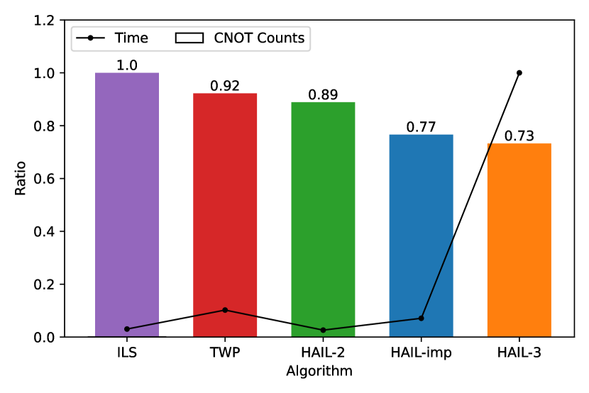
Specifically, We start with a Depth-2 sequence search and select the top sequences based on Eq.6 for further evaluation. Among these sequences, only those with a length of 2 will be extended to a length of 3, as they demonstrate greater potential. In the worst case, the number of sequences of length 3 is , and the total number of all sequences is . This is significantly smaller than the number of sequences generated with a maximum search depth of 3, which is . In the experiments, is set to 50. All these algorithms are tested on the same benchmark, , using the IBM Q20 architecture. As shown in Fig. 7, the improved search algorithm HAIL-imp significantly reduces time with only a slight decrease in overall performance when compared to HAIL-3. Besides, our proposed HAIL outperforms both TWP and ILS in additional inserted SWAP gates when the maximum search depth is 2, and as the search depth increases, the runtime also increases. Specifically, while HAIL-imp results in a 5% increase in CNOT gate insertions compared to HAIL-3, it achieves a 90% reduction in execution time, which represents the desired balance between performance and runtime. Similarly, both the HAIL-2 and ILS algorithms exhibit a slight decrease in execution time compared to HAIL-imp, but they lead to increases in CNOT gate insertions by 15.58% and 29.87%, respectively. In comparison to the TWP algorithm, HAIL-imp not only reduces execution time but also decreases CNOT gate insertions by 16.3%.
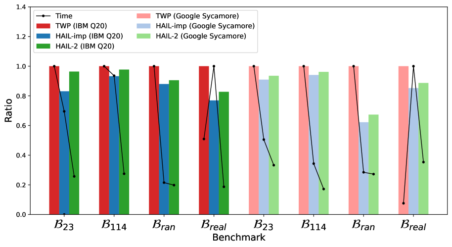
Additionally, to demonstrate the feasibility of the algorithm across different benchmarks, we conduct experiments on the , , and . Since the algorithm TWP outperforms both ILS and SABRE, it is compared only with the proposed algorithm HAIL in these benchmarks, with experiments performed on the IBM Q20 and Sycamore architectures. The experimental results on IBM Q20 are shown in the Fig. 8. According to the results, the HAIL-imp algorithm achieved an approximate 8% reduction in both runtime and the number of additional CNOT gates on the benchmark. On , the number of CNOT gates decreases by 12%, while the runtime is significantly reduced by 78.5%, marking a considerable improvement. However, on the , there is a 23.07% reduction in additional CNOT gates, but the required runtime increases. This may be due to the characteristics of the benchmark, leading to fewer gate executions per decision-making, which in turn increases the whole time. This issue may need to be addressed in future work. Overall, on the IBM Q20 for various benchmarks, HAIL-imp shows a reduction in the number of CNOT gate insertions and time, which also reflects the effectiveness of the algorithm. As for HAIL-2, the algorithm consistently demonstrates fewer CNOT gates and shorter runtime compared to the TWP in these scenarios, but the additional number of CNOT gates inserted is higher than that of HAIL-imp.
Similarly, the experimental results on Sycamore are shown in Fig. 8. As we can see both the HAIL-imp and HAIL-2 algorithms exhibit a reduction in the number of additional CNOT gates inserted compared to the TWP algorithm for the four specified benchmarks on the Sycamore architecture. This reduction is more obvious in the benchmark, where HAIL-imp and HAIL-2 achieve reductions of and , respectively. For the remaining benchmarks, a reduction of approximately 10% is also observed. Notably, the HAIL-imp algorithm consistently inserts fewer additional SWAP gates than HAIL-2. In terms of runtime, the HAIL-imp algorithm demonstrates a longer execution time solely on the benchmark compared to both HAIL-2 and TWP. Furthermore, it is reasonable that HAIL-imp has a longer runtime compared to HAIL-2, as the algorithm’s search space is larger, evaluating a broader range of candidate SWAP sequences. For the other three benchmarks, the runtime of the HAIL-imp algorithm is at least shorter than that of the TWP algorithm, further highlighting the effectiveness and scalability of the proposed algorithms.
5. Conclusion
In this paper, we propose HAIL, an iterative heuristic algorithm designed to tackle the qubit mapping problem, with the objective of minimizing additional SWAP gates. First, we introduce a subgraph isomorphism algorithm based on layer-weight assignment, which generates a more effective initial mapping compared to previous methods that either ignore parallel gates or use gate count as a weighting factor. Since the subgraph isomorphism may result in unmapped qubits, we propose a completion algorithm that considers weight and distance, effectively balancing these properties to address this issue. Then, in the qubit routing stage, a SWAP gate sequence search method and a novel discriminant function with a look-ahead window are proposed to optimize the selection of the SWAP sequence. Additionally, a simplified iterative framework is introduced, utilizing forward-backward techniques with a limited number of iterations to reduce computational costs, which significantly enhances the overall efficiency of the algorithm. We evaluate our algorithm by comparing it with state-of-the-art algorithms, such as SABRE, ILS, and TWP, on the IBM Q20 architecture. Experiments on benchmark demonstrate that HAIL achieves a 20.62% reduction in the number of additional gates compared to TWP and also outperforms SABRE and ILS in terms of performance.
To further optimize the trade-off between runtime and performance, we propose an improved version, HAIL-imp, which reduces the number of candidate SWAP sequences in the HAIL-3 algorithm by partially extending the sequence. Evaluation on both the IBM Q20 and Google Sycamore quantum processors demonstrates significant improvements in runtime and the number of additional SWAP gates compared to TWP. On the benchmark under the Sycamore architecture, the number of additional SWAP gates was reduced by 37.8%, and runtime decreased by 71.52%, confirming the effectiveness and scalability of the algorithm.
acknowledgments
This research was supported by the National Nature Science Foundation of China (Grant No. 62101600, Grant No. 62471070), the Science Foundation of the China University of Petroleum, Beijing (Grant No. 2462021YJRC008), and the State Key Lab of Processors, Institute of Computing Technology, CAS (Grant No. CLQ202404).
References
- (1) R. P. Feynman et al., “Simulating physics with computers,” Int. j. Theor. phys, vol. 21, no. 6/7, 2018.
- (2) P. W. Shor, “Algorithms for quantum computation: discrete logarithms and factoring,” in Proceedings 35th annual symposium on foundations of computer science. Ieee, 1994, pp. 124–134.
- (3) L. K. Grover, “A fast quantum mechanical algorithm for database search,” in Proceedings of the twenty-eighth annual ACM symposium on Theory of computing, 1996, pp. 212–219.
- (4) A. W. Harrow, A. Hassidim, and S. Lloyd, “Quantum algorithm for linear systems of equations,” Physical review letters, vol. 103, no. 15, p. 150502, 2009.
- (5) L. Li, J. Li, Y. Song, S. Qin, Q. Wen, and F. Gao, “An efficient quantum proactive incremental learning algorithm,” Science China Physics, Mechanics & Astronomy, vol. 68, no. 1, pp. 1–9, 2025.
- (6) Y. Song, Y. Wu, S. Wu, D. Li, Q. Wen, S. Qin, and F. Gao, “A quantum federated learning framework for classical clients,” Science China Physics, Mechanics & Astronomy, vol. 67, no. 5, p. 250311, 2024.
- (7) D. Castelvecchi, “Ibm releases first-ever 1,000-qubit quantum chip,” Nature, vol. 624, no. 7991, pp. 238–238, 2023.
- (8) X. Sun, G. Tian, S. Yang, P. Yuan, and S. Zhang, “Asymptotically optimal circuit depth for quantum state preparation and general unitary synthesis,” IEEE Transactions on Computer-Aided Design of Integrated Circuits and Systems, vol. 42, no. 10, pp. 3301–3314, 2023.
- (9) A. Botea, A. Kishimoto, and R. Marinescu, “On the complexity of quantum circuit compilation,” in Proceedings of the International Symposium on Combinatorial Search, vol. 9, no. 1, 2018, pp. 138–142.
- (10) M. Y. Siraichi, V. F. d. Santos, C. Collange, and F. M. Q. Pereira, “Qubit allocation,” in Proceedings of the 2018 International Symposium on Code Generation and Optimization, 2018, pp. 113–125.
- (11) Y. Ge, W. Wenjie, C. Yuheng, P. Kaisen, L. Xudong, Z. Zixiang, W. Yuhan, W. Ruocheng, and Y. Junchi, “Quantum circuit synthesis and compilation optimization: Overview and prospects,” 2024. [Online]. Available: https://arxiv.org/abs/2407.00736
- (12) A. Shafaei, M. Saeedi, and M. Pedram, “Qubit placement to minimize communication overhead in 2d quantum architectures,” in 2014 19th Asia and South Pacific Design Automation Conference (ASP-DAC). IEEE, 2014, pp. 495–500.
- (13) G. Nannicini, L. S. Bishop, O. Günlük, and P. Jurcevic, “Optimal qubit assignment and routing via integer programming,” ACM Transactions on Quantum Computing, vol. 4, no. 1, pp. 1–31, 2022.
- (14) D. Bhattacharjee and A. Chattopadhyay, “Depth-optimal quantum circuit placement for arbitrary topologies,” arXiv preprint arXiv:1703.08540, 2017.
- (15) D. Bhattacharjee, A. A. Saki, M. Alam, A. Chattopadhyay, and S. Ghosh, “Muqut: Multi-constraint quantum circuit mapping on nisq computers,” in 2019 IEEE/ACM international conference on computer-aided design (ICCAD). IEEE, 2019, pp. 1–7.
- (16) B. Tan and J. Cong, “Optimal qubit mapping with simultaneous gate absorption,” in 2021 IEEE/ACM International Conference On Computer Aided Design (ICCAD). IEEE, 2021, pp. 1–8.
- (17) P. Murali, J. M. Baker, A. Javadi-Abhari, F. T. Chong, and M. Martonosi, “Noise-adaptive compiler mappings for noisy intermediate-scale quantum computers,” in Proceedings of the twenty-fourth international conference on architectural support for programming languages and operating systems, 2019, pp. 1015–1029.
- (18) A. Lye, R. Wille, and R. Drechsler, “Determining the minimal number of swap gates for multi-dimensional nearest neighbor quantum circuits,” in The 20th Asia and South Pacific Design Automation Conference. IEEE, 2015, pp. 178–183.
- (19) R. Wille, L. Burgholzer, and A. Zulehner, “Mapping quantum circuits to ibm qx architectures using the minimal number of swap and h operations,” in Proceedings of the 56th Annual Design Automation Conference 2019, 2019, pp. 1–6.
- (20) A. Molavi, A. Xu, M. Diges, L. Pick, S. Tannu, and A. Albarghouthi, “Qubit mapping and routing via maxsat,” in 2022 55th IEEE/ACM International Symposium on Microarchitecture (MICRO). IEEE, 2022, pp. 1078–1091.
- (21) W.-H. Lin, J. Kimko, B. Tan, N. Bjørner, and J. Cong, “Scalable optimal layout synthesis for nisq quantum processors,” in 2023 60th ACM/IEEE Design Automation Conference (DAC). IEEE, 2023, pp. 1–6.
- (22) X. Zhou, Y. Feng, and S. Li, “A monte carlo tree search framework for quantum circuit transformation,” in Proceedings of the 39th International Conference on Computer-Aided Design, 2020, pp. 1–7.
- (23) A. Sinha, U. Azad, and H. Singh, “Qubit routing using graph neural network aided monte carlo tree search,” in Proceedings of the AAAI Conference on Artificial Intelligence, vol. 36, no. 9, 2022, pp. 9935–9943.
- (24) M. G. Pozzi, S. J. Herbert, A. Sengupta, and R. D. Mullins, “Using reinforcement learning to perform qubit routing in quantum compilers,” ACM Transactions on Quantum Computing, vol. 3, no. 2, pp. 1–25, 2022.
- (25) Y. Li, W. Liu, and M. Li, “Deep reinforcement learning for mapping quantum circuits to 2d nearest-neighbor architectures,” Advanced Quantum Technologies, vol. 7, no. 2, p. 2300289, 2024.
- (26) H. Fan, C. Guo, and W. Luk, “Optimizing quantum circuit placement via machine learning,” in Proceedings of the 59th ACM/IEEE Design Automation Conference, 2022, pp. 19–24.
- (27) X. Zhou, Y. Feng, and S. Li, “Supervised learning enhanced quantum circuit transformation,” IEEE Transactions on Computer-Aided Design of Integrated Circuits and Systems, vol. 42, no. 2, pp. 437–447, 2022.
- (28) A. Paler, L. Sasu, A.-C. Florea, and R. Andonie, “Machine learning optimization of quantum circuit layouts,” ACM Transactions on Quantum Computing, vol. 4, no. 2, pp. 1–25, 2023.
- (29) A. Matsuo and S. Yamashita, “Changing the gate order for optimal lnn conversion,” in Reversible Computation: Third International Workshop, RC 2011, Gent, Belgium, July 4-5, 2011. Revised Papers 3. Springer, 2012, pp. 89–101.
- (30) A. Zulehner, A. Paler, and R. Wille, “An efficient methodology for mapping quantum circuits to the ibm qx architectures,” IEEE Transactions on Computer-Aided Design of Integrated Circuits and Systems, vol. 38, no. 7, pp. 1226–1236, 2018.
- (31) G. Li, Y. Ding, and Y. Xie, “Tackling the qubit mapping problem for nisq-era quantum devices,” in Proceedings of the Twenty-Fourth International Conference on Architectural Support for Programming Languages and Operating Systems, 2019, pp. 1001–1014.
- (32) A. Ash-Saki, M. Alam, and S. Ghosh, “Qure: Qubit re-allocation in noisy intermediate-scale quantum computers,” in Proceedings of the 56th Annual Design Automation Conference 2019, 2019, pp. 1–6.
- (33) S. Niu, A. Suau, G. Staffelbach, and A. Todri-Sanial, “A hardware-aware heuristic for the qubit mapping problem in the nisq era,” IEEE Transactions on Quantum Engineering, vol. 1, pp. 1–14, 2020.
- (34) L. Lao and D. E. Browne, “2qan: A quantum compiler for 2-local qubit hamiltonian simulation algorithms,” in Proceedings of the 49th Annual International Symposium on Computer Architecture, 2022, pp. 351–365.
- (35) Y. Li, Y. Zhang, M. Chen, X. Li, and P. Xu, “Timing-aware qubit mapping and gate scheduling adapted to neutral atom quantum computing,” IEEE Transactions on Computer-Aided Design of Integrated Circuits and Systems, 2023.
- (36) S. Li, X. Zhou, and Y. Feng, “Qubit mapping based on subgraph isomorphism and filtered depth-limited search,” IEEE Transactions on Computers, vol. 70, no. 11, pp. 1777–1788, 2020.
- (37) P. Zhu, S. Feng, and Z. Guan, “An iterated local search methodology for the qubit mapping problem,” IEEE Transactions on Computer-Aided Design of Integrated Circuits and Systems, vol. 41, no. 8, pp. 2587–2597, 2021.
- (38) Y. Qian, Z. Guan, S. Zheng, and S. Feng, “A method based on timing weight priority and distance optimization for quantum circuit transformation,” Entropy, vol. 25, no. 3, p. 465, 2023.
- (39) H. Jiang, Y. Deng, and M. Xu, “Quantum circuit transformation based on tabu search,” arXiv preprint arXiv:2104.05214, 2021.
- (40) K. Datta, A. Kole, I. Sengupta, and R. Drechsler, “Improved cost-metric for nearest neighbor mapping of quantum circuits to 2-dimensional hexagonal architecture,” in International Conference on Reversible Computation. Springer, 2023, pp. 218–231.
- (41) K.-Y. Chang and C.-Y. Lee, “Mapping nearest neighbor compliant quantum circuits onto a 2-d hexagonal architecture,” IEEE Transactions on Computer-Aided Design of Integrated Circuits and Systems, vol. 41, no. 10, pp. 3373–3386, 2021.
- (42) A. Ovide, S. Rodrigo, M. Bandic, H. Van Someren, S. Feld, S. Abadal, E. Alarcon, and C. G. Almudever, “Mapping quantum algorithms to multi-core quantum computing architectures,” arXiv preprint arXiv:2303.16125, 2023.
- (43) J. Liu, E. Younis, M. Weiden, P. Hovland, J. Kubiatowicz, and C. Iancu, “Tackling the qubit mapping problem with permutation-aware synthesis,” in 2023 IEEE International Conference on Quantum Computing and Engineering (QCE), vol. 1. IEEE, 2023, pp. 745–756.
- (44) P. Zhu, Z. Guan, and X. Cheng, “A dynamic look-ahead heuristic for the qubit mapping problem of nisq computers,” IEEE Transactions on Computer-Aided Design of Integrated Circuits and Systems, vol. 39, no. 12, pp. 4721–4735, 2020.
- (45) C.-Y. Huang and W.-K. Mak, “Efficient qubit routing using a dynamically-extract-and-route framework,” IEEE Transactions on Computer-Aided Design of Integrated Circuits and Systems, 2024.
- (46) B. Tan and J. Cong, “Optimality study of existing quantum computing layout synthesis tools,” IEEE Transactions on Computers, vol. 70, no. 9, pp. 1363–1373, 2020.
- (47) L. Cordella, P. Foggia, C. Sansone, and M. Vento, “A (sub)graph isomorphism algorithm for matching large graphs,” IEEE Transactions on Pattern Analysis and Machine Intelligence, vol. 26, no. 10, pp. 1367–1372, 2004.