standard \DeclareDatamodelEntryfields[standard]type,number \DeclareBibliographyCategoryneedsurl \addtocategoryneedsurlsiemensplmsoftware2018
Towards Closing the Gap between Model-Based Systems Engineering and Automated Vehicle Assurance: Tailoring Generic Methods by Integrating Domain Knowledge
Abstract
Designing, assuring and releasing safe automated vehicles is a highly interdisciplinary process. As complex systems, automated driving systems will inevitably be subject to emergent properties, i. e. the properties of the overall system will be more than just a sum of the properties of its integrated elements. Safety is one example of such emergent properties. In this regard, it must be ensured that effects of emergence do not render an overall system that is composed of safety-approved sub systems unsafe.
The key challenges in this regard are twofold: Regarding the interdisciplinary character of the development and assurance processes, all relevant stakeholders must speak a common language and have a common understanding of the key concepts that influence system safety. Additionally, the individual properties of system elements should remain traceable to the system level.
Model-Based Systems Engineering (MBSE) provides an interdisciplinary mindset, as well as methods and processes to manage emergent system properties over the entire system lifecycle. By this, MBSE provides tools that can assist the assurance process for automated vehicles. However, concepts from the domain of MBSE have a reputation for not being directly accessible for domain experts who are no experts in the field of Systems Engineering.
This paper highlights challenges when applying MBSE methods to the design and development of automated driving systems. It will present an approach to create and apply domain-specific SysML profiles, which can be a first step for enhancing communication between different stakeholders in the development and safety assurance processes.
Keywords: Traceability, (Model-Based) Systems Engineering, Domain Modeling
1 Motivation
The challenges related to the assurance of automated driving systems, i.e. proving that automated vehicles do not pose an unreasonable risk to its passengers and other traffic participants, are still manifold. Research questions remain all along the process, e.g., from defining risk acceptance criteria over performing effective safety analyses to the effective verification and validation of AI-based system components.
A challenge in this context is that different stakeholders in the assurance process come from different disciplines with different qualifications and different mindsets. Safety- and System Engineers must, e.g., work together with AI-experts, function developers and/or Test Engineers. As such, [1] highlight that safety engineering must be treated as a highly interdisciplinary process that must solve a “set of coupled problems […] in a coordinated, cross-domain manner.” [1, 91]
This is a challenge that Systems Engineering is supposed to solve: The International Council on Systems Engineering (INCOSE) defines Systems Engineering as “a transdisciplinary and integrative approach to enable the successful realization, use, and retirement of engineered systems […]” [2]. A central concern in Systems Engineering processes is the management of complexity and emergent system properties. For this purpose, Model-Based Systems Engineering (MBSE)333MBSE combines Systems Engineering processes with (semi-) formal models (e.g., defined in SysML [3]) for modeling requirements, architectures, test specifications, and other process artefacts. provides (semi-) formal methods for modeling the system and related elements. These models facilitate traceability between the different artefacts which are generated during design, development, and assurance.
While MBSE-based methods and processes show great potential for rigorous development and assurance processes in the domain of automated driving, there are significant adoption challenges in industry settings [4]. Besides typical ressentiments such as the steep learning curve and the modeling overhead that come with MBSE-adoption processes, [4] discuss the importance of introducing domain knowledge into the modeling process. Furthermore, model-based methods cannot ensure the completeness of the generated models. Also, scalability can be questioned, when the models become larger and more complex. However, model-based approaches can help significantly to ensure the consistency of the modeled artefacts. In this regard, integrating domain knowledge can help to make models more accessible for domain experts. This can facilitate communication between Systems Engineers and domain experts and by this indirectly help to capture relevant system properties and requirements. Furthermore, applying domain knowledge can help to facilitate the integration of domain-specific tooling with the models.
We will outline an approach to tailor established (MB)SE processes using domain knowledge in the field of automated driving by creating domain-specific SysML profiles. The approach is based on a comparative analysis of selected standards in the field of automated driving and the central process standard for Systems- and Software Engineering (\citenormtiso15288-23). Based on this analysis, examples for common concepts from those standards in both domains will be extracted and documented in a corresponding concept model. This concept model will be used as a basis for creating an example of a domain-specific SysML profile which can be used to model AD-specific artefacts (or work products) that can contribute to a traceable system specification.
2 Related Work
Recent research [6, 7, 8, 9] and industry position papers [10] show that the application of MBSE for the design and assurance of automated vehicles is gaining traction.
[6] describe an MBSE-driven approach for deriving a logical architecture from use case and scenario descriptions. They apply MBSE processes to domain-specific ideas of scenario-based development for automated vehicles, creating models that reflect a model-based and SOTIF-compliant assurance case in Goal Structuring Notation. [7] focus on an MBSE-supported generation of scenarios for verification and validation. [9] as well as [8] apply an MBSE-based architecture framework to the definition of vehicle concepts and mobility services offered by automated vehicles.
The authors in all examples apply principles from MBSE without domain-specific tailoring of the required concepts, as suggested by [4]. The authors of the Systems Architecture Framework (SAF [11])444See modeling approach at https://github.com/GfSE/SAF-Specification/blob/main/developing-saf/development.md (visited 09/26/24). show how a traceable definition of concept models and SysML profiles for domain-specific modeling can be achieved.
3 Translating from Systems Engineering Concepts to Domain-Specific Concepts
A plethora of different concepts has been introduced in the field of automated driving to address the needs of the various stakeholders in the development and assurance process. The Operational Design Domain (\citenormtiso34503), behavioral competencies [13] or a particular domain-specific understanding of Scenarios (\citenormtiso21448, \citenormtiso34501) are prominent examples of such concepts. Regarding safety assurance, \citenormtiso2018 and \citenormtiso21448 (SOTIF) have introduced domain-specific artefacts and process steps that are mandatory to create and perform to claim standard compliance.
In the field of Systems Engineering, \citenormtiso15288-23 defines a generic Systems Engineering process framework for managing the entire system life cycle. The standard rigorously defines processes in an input-process-output (IPO) scheme, meaning that not only the process steps themselves are defined, but also the required input artefacts to perform the processes and their expected output artefacts.
The relevant automotive standards do, in general, not refer to details of the generic Systems Engineering standards such as \citenormtiso15288-23. However, when comparing the processes and artefacts defined by \citenormtiso15288-23 with the different terms and concepts in the domain-specific standards such as \citenormtiso34503, \citenormtiso2018 or \citenormtiso21448, it becomes apparent that while the automotive domain has introduced its own terminology, there is a strong overlap between the underlying concepts. Footnote˜5 shows how artefacts that are required by \citenormtiso2018 and \citenormtiso21448 can be mapped to processes defined by \citenormtiso15288-23.
To design and maintain an actual product from an initial business goal of an organization, \citenormtiso15288-23 defines processes and support processes, among others, a) to capture the organization’s business mission (Business or Mission Analysis Process), b) to align this business mission with customer (or more general “stakeholder”) needs (Stakeholder Needs and Requirements Definition Process), c) to derive concrete requirements from those stakeholder needs and requirements (System Requirements Definition Process), d) to define the (functional, logical, and physical) system architecture (System Architecture Definition Process), and e) to assign (or allocate) requirements to architectural elements into a coherent system design (System Design Definition Process).666Note that the \citenormtiso15288-23 defines additional processes that target the entire system life cycle. For the sake of the argument, we will focus on the processes that can be aligned with the Design Phase according to \citenormt[][-3]iso2018.
In the automotive domain, the central document that initiates the \citenormyiso2018 reference process is the Item Definition. The analogous document within the \citenormyiso21448 is the Specification and Design. Comparable artefacts between both documents are displayed in Footnote˜5: According to \citenormt[-3][pp. 4f.]iso2018, among others, the item definition should be based on:
-
1.
legal requirements, national & international standards (which can be summarized as normative stakeholder requirements),
-
2.
(assumed) actuator potentials (e.g., maximum torque, forces, etc.),
-
3.
assumptions regarding the item’s behavior at vehicle level and the “operational scenarios” which concern the item’s functionality,
-
4.
requirements (quality, performance, availability) regarding the item’s functionality,
-
5.
the item’s boundary, its interfaces and assumptions regarding its interaction with other items and elements (which can be summarized as a preliminary functional or logical architecture),
-
6.
the allocation and distribution of functions among the involved systems and elements (combined with existing functional requirements \citenormp[-3][Clause 5.4.1, p. 4, NOTE 2]iso2018; this corresponds to a preliminary functional design).
In different formulations, the points 2 to 6 can also be found inside the specification and design according to \citenormyiso21448. The description of assumptions regarding the item’s behavior at the vehicles and the operational scenarios are summarized as use cases, development scenarios, and the interaction of the automated driving system with external entities. For SOTIF, this also includes the definition of an initial (rudimentary) Operational Design Domain. For the specification and design, \citenormyiso21448 also expects performance targets for “sensors, controllers and actuators or other [System-] inputs and components” \citenormp[Clause 5.2, p. 21]iso21448 which includes items 2 and 3 above. Finally, SOTIF demands a definition of “system and vehicle architectures implementing the intended functionality” and of “the design of the relevant system and its elements implementing the intended functionality” \citenormp[Clause 5.2, pp. 21f.]iso21448. These requirements regarding architectures and design include the bullets 5 and 6, but require additional technical architectures and designs compared to the functional architecture and design required for the \citenormyiso2018 item definition.
Footnote˜5, which maps the artefacts described above to the \citenormyiso15288-23-processes, shows that stakeholder needs and requirements do not play central roles in \citenormyiso2018 or \citenormyiso21448: \citenormyiso2018 focuses on normative stakeholder requirements when are derived from regulation and standards, SOTIF does not explicitly mention stakeholder needs or requirements at all. At the same time, SOTIF demands the definition of (risk) acceptance criteria, which from a Systems Engineering perspective, cannot be defined without proper stakeholder needs analyses.
Regarding the definition of use cases, assumptions about the vehicle behavior, the definition of an Operational Design (or Targeted Operational) Domain (ODD / TOD), as well as the definition of interfaces of the automated driving system (or vehicle-level Item for \citenormyiso2018) constitute parts of an Operational Concept777The Operational Concept is a document that aims at describing the purpose of a system, primarily from the perspective of assumed stakeholders. \citenormpiso15288-23 (OpsCon) according to \citenormyiso15288-23.
The demanded preliminary requirements, the (preliminary or legacy) functional and physical architectures, as well as the (preliminary) functional and physical designs in \citenormyiso2018 and \citenormyiso21448 can be attributed to the System Requirements Definition, the System Architecture Definition and the System Design Definition Processes in \citenormyiso15288-23. All \citenormyiso2018 and \citenormyiso21448 processes related to hazard and risk assessments (HARA) can be attributed to \citenormyiso15288-23 risk management processes (not displayed in Footnote˜5).
Regarding traceability between the different artefacts, \citenormt[-5][Clause 7.4.1.5, p. 10]iso2018 and \citenormt[-6][Clause 7.4.2 a), p. 11]iso2018 demand the traceability of hardware and software safety requirements to the hardware and software architectural designs, respectively. \citenormyiso21448 considers traceability as “desirable”, but does not make specific requirements. In contrast to that, \citenormyiso15288-23 defines “traceability documentation” as a required artefact for each defined process.
Critical Assessment of Automotive Standards
Summarizing, the comparison of \citenormyiso15288-23 with the established automotive safety standards \citenormyiso2018 and \citenormyiso21448 shows that the generic Systems Engineering standard contains more demands regarding traceable system (architecture) design. As some of the artefacts required by \citenormyiso2018 and \citenormyiso21448 can be unambiguously assigned to \citenormyiso15288-23 process requirements, it seems promising to structure these common artefacts in a way such that they become compatible to established Systems Engineering practices and such that redundant work can be avoided.
At the same time, compared to established Systems Engineering practices, particularly early design phase artefacts that are connected to capturing and tracing stakeholder values, needs, and requirements are rarely considered in the automotive safety standards. This is explainable, as for established automotive systems, the main stakeholder has long been the customer, and automotive OEMs have historically been well-equipped to identify customer needs. Even for simpler SAE-Level-2 systems, as the human driver always remains in control, it may not be immediately necessary to consider the more general Systems Engineering processes that are related to defining thorough operational concepts. However, at the least when SAE-Level-4 systems are concerned, these systems impact a variety of stakeholder groups, most importantly the general public.
In this sense, closing this gap between a wide body of knowledge for the design of safe automotive systems and the more generic Systems Engineering processes have the potential to enable a) the required interdisciplinary collaboration described in Section˜1, and b) establish frameworks for better communication with non-technical stakeholders.
4 From Translated Concept Models to Domain-Specific Models
Identifying common artefacts and allocating these artefacts to the generic Systems Engineering processes defined by \citenormyiso15288-23 is only a first step for closing this aforementioned gap. A key challenge remains in translating and structuring (or formalizing) the translated concepts between both fields.
As argued in Section˜1, applying approaches from Model-Based Systems Engineering to the domain of automated driving is promising, when it comes to establishing traceability along the entire system life cycle. For the implementation of MBSE-supported processes in the automated driving domain, there are two challenges that are closely related to concerns regarding the steep learning curve and the overhead that is often attributed [4] to MBSE. a) Oftentimes, experts who possess rich domain knowledge and the required (meta-) modeling expertise are difficult to come by. b) The modeling language is typically not tailored towards the specific application domains, causing communication challenges between System Engineers and domain experts.
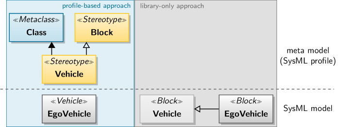
To overcome these challenges, two approaches can be taken (cf. Figure˜2): The first is based on so-called “libraries”: No special SysML profile is created in this case. Specific model elements can inherit from generic, domain-specific elements, comparable to object-oriented approaches in modern programming languages. While the use of such libraries is beneficial for reusing knowledge which has already been captured in specific model elements, the model’s stereotypes remain generic and are not tailored toward the application domain.
An approach for such tailoring is described by [17]. This approach includes the creation of domain-specific meta models. The authors suggest a three-stage process that shall assist capturing domain-specific expert knowledge and apply this knowledge for system modeling. According to [17], this helps to ensure that created models stay consistent to captured knowledge. The proposed process is built on
-
1.
capturing domain-specific knowledge in ontologies,
-
2.
creating domain-specific meta models from the ontologies, and
-
3.
applying the meta models for creating domain-specific models.
Translated to a SysML-supported MBSE approach, the creation of the meta models requires domain-specific SysML profiles. These profiles provide custom SysML Stereotypes for model elements and their respective relations. This process is also followed by current MBSE-heavy architecture frameworks such as the Unified Architecture Framework (UAF, \citenormyiso19540): The creators of the UAF provide a plethora of concept models, modeled as ontologies, to capture relevant knowledge about the design of enterprise architectures. Based on these ontologies, UAF defines the “Unified Architecture Framework Modeling Language” (UAFML) [19].
4.1 From Domain Ontologies to Domain-Specific SysML Profiles
We adopt this approach, as it has two major advantages compared to a library-only model:
-
1.
The domain ontologies serve as part of a consistent knowledge-base for the design, development, and assurance process, and
-
2.
profile elements that are derived from the ontologies are always traceable to the structured expert knowledge.
This allows to establish consistent traceability from the elicitation of expert knowledge at the very beginning of the design process to the actual system design (i.e., architectures and requirements), and possibly also to generated source code and runtime artefacts in later process stages or at system runtime.
In the following, we will give a concrete example for this approach by defining an example scenario which can, e.g., serve as an input for safety analyses. A simplified excerpt from the created concept models and the domain-specific SysML profile is shown in Figure˜3. The “domain ontology” contains concepts and relations from the automated driving domain (AD domain, gray boxes, black arrows) and the Systems Engineering domain (SE domain, orange boxes and arrows). For the automated driving domain (AD-domain), the ontology defines that the Ego Vehicle and Pedestrians are Traffic Participants which are entities at Layer 4 of the 6-Layer model. Following [21], these entities constitute elements of a Scene, while a Scenario consists of a temporal sequence of Scenes. In the AD domain and the SE domain, scenarios can be part of a Use Case that summarizes similar scenarios.888Note that this relation is already defined by [21] in relation to established Systems Engineering practice. An important concept in the SE domain is the (System) Context which defines the elements that a System of Interest needs to interact with. Translated to the AD domain, the System Context can be described by the union of all Scene Entities, which an automated vehicle interacts with, in a scenario. Hence, the System Context is considered as a part of a scenario, whereas Scene Entities are part of the System Context itself.
In the SE domain, The Unified Architecture Framework introduces the concept of an Agent which is an abstract, generalizing concept of an entity that can show their own intentions in a use case (or scenario) by exhibiting behavior.999In the UAF ontology, agents are implemented by resources which can be systems, people or parts of an organization.[22] We add the agent as an intermediate concept that generalizes Traffic Participants at Layer 4 of the 6-Layer Model. In the example, this includes the Ego Vehicle and a Pedestrian. Agents are able to perform Target Behavior in a given Scenario, that defines a particular (System) Context. This includes, but is not limited to, a technical definition of the Ego Vehicle’s Target Behavior. This behavior can, e.g., be modeled in terms of required maneuvers to fulfill its mission.101010By modeling the relations in this way, we leave the option of modeling a defined target behavior in a scenario for other traffic participants, e.g. for defining behavior for simulated scenarios.
Examples of how the concepts in the domain ontology are translated to elements in a domain-specific SysML profile can be seen above and below the ontology in Figure˜3. We introduce custom SysML stereotypes which specialize existing stereotypes in the SysML 1.4 profile. Examples are the «Ego» and «Pedestrian» Stereotypes which specialize the common «Block» SysML stereotype. That the corresponding Scene Entities can be part of a (System) Context is expressed by tracing the SysML «PartAssociation» to the part_of relation. The concept of the (System) Context is simply traced to the according, already existing, SysML stereotype.
4.2 Creating Models Based on Domain-Specific SysML Profiles
With the domain-specific SysML profile established, it is possible to model domain-specific views (cf. [23, 24]). For this example, we will focus on modeling contents of the Operational Concept (cf. Section˜3) in terms of use cases, system contexts and scenarios which can be used to analyze the system of interest from the perspective of stakeholder needs. As discussed, the contents of the Operational Concept are also important artefacts for starting the safety lifecycle according to \citenormyiso2018 and \citenormyiso21448. By providing parts of a model-based Operational Concept, we introduce the basis for the traceable definition and implementation of safety requirements along the assurance process.
The example is based on the scenario that is shown in Figure˜4: The Ego Vehicle passes a row of parked Vehicles. A Pedestrian is about to step onto the street between the first and second parked Vehicle.
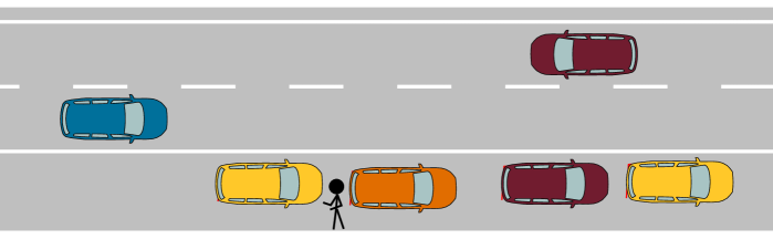
The scenario can be modeled in SysML as part of a Use Case “Passing Parked Vehicles” (Figure˜5, top) which subsumes similar scenarios. While use cases give a general impression with which entities a system of interest has to interact (Actors, [25]), the Context Diagram (Figure˜5, bottom) provides additional detail per scenario: It can capture how many actors of a particular kind are present in a scenario; the actors can be decomposed further for providing additional details. Note that the actors carry domain-specific stereotypes, which according to [17], can enable easier communication about the related models between stakeholders.
In the particular example, it can be seen that the ego vehicle needs to interact with the parked vehicles, the road markings, and the pedestrian. For a full specification of all relevant scene entities in the scenario, the road is decomposed into its lanes and the parking lane.
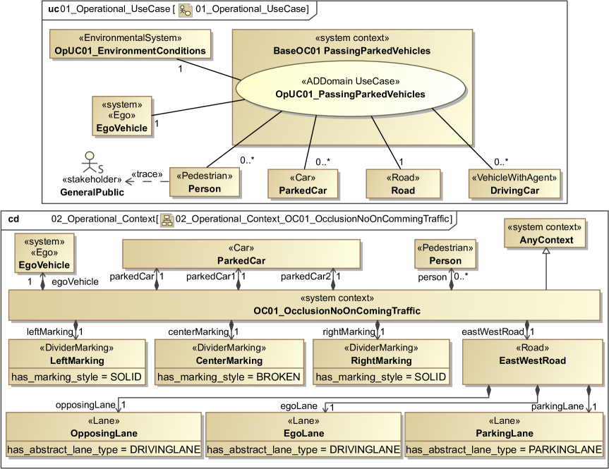
The corresponding lane markings are direct parts of the system context due to the concepts in the six layer domain ontology.111111As a context diagram typically only shows directed part of relationships (directed association with filled diamond), the relation between divider markings and lanes (Lane “has neighbor” Divider) is not explicitly displayed. Individual elements of the use case (or system context) can also be traced directly to stakeholders who might be affected by the automated driving system in a given scenario. In the given example, the person in Figure˜5 (top) is traced to the stakeholder group representing the general public.
With Sequence Diagrams, SysML provides a diagram type which can be used to create SysML representations of functional [26] or abstract [27] scenarios (cf. Figure˜6), based on the system context. The resulting sequence chart depicts how the automated vehicle needs to interact with the elements of the system context to fulfill its mission.

5 Conclusion & Future Work
The models shown in Section˜4.2 give an example how parts of an Operational Concept for an automated driving system can be modeled in SysML. As discussed in Section˜3, a well-defined Operational Concept can assist in merging general Systems Engineering Processes with existing automotive safety processes according to \citenormyiso2018 and \citenormyiso21448. In this regard, the presented models can provide a semiformal option to model the artefacts required for initiating hazard and risk assessments that are compatible with both standards, which require
-
•
use cases,
-
•
(operational) scenarios,
-
•
interactions of the automated driving system / item with its environment, and
-
•
traceable relations to stakeholder needs and requirements.
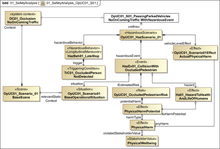
The application of AD-domain-specific knowledge and terminology for the creation of the models is an option to provide better communication about the contents of the models. Last but not least, the SysML models can also be used as a basis to conduct model-based safety analysis to support the generation of traceable safety concepts (Figure˜7).
While the discussed approach shows great potential to support the traceable design of safe automated driving systems, model-based approaches suffer similar scalability issues as all scenario-based approaches: Due to the complexity of the real, open world, it is impossible to capture all relevant scenarios at design time. Efficient design approaches must hence strike a balance between deriving context-specific and context-agnostic requirements.
However, as e.g. [28] and [29] argue, net risk arguments121212I.e., “The system is times better than a human driver in its ODD.” will always require support from edge- or corner-case-based (and hence scenario-based) arguments that an automated driving system is “free from unreasonable risk”. In this respect, the scenario-based hazard and risk assessments which can be supported by the presented approach will always be required. Model-based consistency and traceability of the created artefacts can greatly assist consistent assurance processes.
Future work will focus on simplifying and automating the modeling process for non Systems Engineers: Even with the domain-specific models, the manual creation of the discussed diagrams can still be tedious, specifically for domain experts who have little to no MBSE experience. We assume that simplifying the modeling process can help the acceptance of MBSE-methods in practice. With the existing meta models as a ground truth that ensures consistency, the creation of what-you-see-is-what-you-get tools that enable a guided modeling process seems promising. As the entire approach is based on formalized expert knowledge, it also seems promising to explore how the model-generation process can be automated by combining the existing knowledge with ODD [30] and scenario description languages [31].
Acknowledgement
We would like to thank our former partners in the project VVMethods (funded by the German Federal Ministry for Economic Affairs and Climate Action, 2019–2023) for fruitful discussions that led to the conclusions presented in this paper. We would like to thank the German Federal Ministry for Economic Affairs and Climate Action for funding parts of this work in the context of the Project “Automatisierter Transport zwischen Logistikzentren auf Schnellstraßen im Level 4 (ATLAS-L4)”.
References
- [1] Philip Koopman and Michael Wagner “Autonomous Vehicle Safety: An Interdisciplinary Challenge” In IEEE Intelligent Transportation Systems Magazine 9.1, 2017, pp. 90–96 DOI: 10.1109/MITS.2016.2583491
- [2] “INCOSE Systems Engineering Handbook” Hoboken, NJ: John Wiley & Sons Ltd, 2023
- [3] Object Management Group (OMG) “OMG Systems Modeling Language™(SysML®) – Version 1.6”, 2019 URL: https://www.omg.org/spec/SysML/1.6
- [4] Josua Blott and Christian Buchholz “Challenges of Implementing MBSE in Industry: A Tool Vendor Experience” In Engineering for a Changing World: Proceedings : 60th ISC Ilmenau Scientific Colloquium Thüringer Universitäts- und Landesbibliothek Jena, 2023, pp. 1–11 DOI: 10.22032/DBT.58895
- [5] International Organization for Standardization (ISO), International Electrotechnical Commission (IEC) and Institute of Electrical and Electronics Engineers (IEEE) “Systems and Software Engineering — System Life Cycle Processes” IEEE, 2023 DOI: 10.1109/IEEESTD.2023.10123367
- [6] Max-Arno Meyer, Sebastian Silberg, Christian Granrath, Christopher Kugler, Louis Wachtmeister, Bernhard Rumpe, Sebastien Christiaens and Jakob Andert “Scenario- and Model-Based Systems Engineering Procedure for the SOTIF-Compliant Design of Automated Driving Functions” In 2022 IEEE Intelligent Vehicles Symposium (IV) Aachen: IEEE, 2022, pp. 1599–1604 DOI: 10.1109/IV51971.2022.9827151
- [7] Serdar Kinay, Ufuk Bolat, Buse Yakin Gökdemir, Kaan Babacan, Namik Zengin and Erhan Özkaya “Advancing MBSE for ADAS/AD: Automated Scenario Generation” In 2024 IEEE/SICE International Symposium on System Integration (SII) Ha Long, Vietnam: IEEE, 2024, pp. 1583–1588 DOI: 10.1109/SII58957.2024.10417219
- [8] Tarık Şahin, Christian Raulf, Volkan Kızgın, Tobias Huth and Thomas Vietor “A Cross-domain System Architecture Model of Dynamically Configurable Autonomous Vehicles” In 21. Internationales Stuttgarter Symposium, Proceedings Stuttgart: Springer Fachmedien, 2021, pp. 13–31 DOI: 10.1007/978-3-658-33521-2_2
- [9] Christian Raulf “Modellbasierte Entwicklung innovativer Fahrzeugkonzepte für die Mobilität der Zukunft”, 2023
- [10] Siemens PLM Software “Model-Based Systems Engineering for Autonomous Vehicle Development”, 2018 URL: https://www.plm.automation.siemens.com/media/global/ko/Siemens-PLM-Model-based-systems-engineering-for-autonomous-vehicle-development-wp-31354-A3_tcm72-52979.pdf
- [11] Michael Leute, Alexander Haarer, Sascha Ackva, Christian Lalitsch-Schneider, Markus Andres, Stephan Husung and Piotr Malecki “Modellbasierter Bärentango mit dem System Architecture Framework” In Tag des Systems Engineering (TdSE) online: Gesellschaft für Systems Engineering e.V., 2021
- [12] International Organization for Standardization (ISO) “Road Vehicles — Test Scenarios for Automated Driving Systems — Specification for Operational Design Domain” ISO, 2023
- [13] Automated Vehicle Safety Consortium (AVSC) “AVSC Best Practice for Evaluation of Behavioral Competencies for Automated Driving System Dedicated Vehicles (ADS-DVs)”, 2021
- [14] International Organization for Standardization (ISO) “Road Vehicles — Safety of the Intended Functionality” ISO, 2022
- [15] International Organization for Standardization (ISO) “Road Vehicles — Test Scenarios for Automated Driving Systems — Vocabulary” ISO, 2022
- [16] International Organization for Standardization (ISO) “Road Vehicles — Functional Safety” ISO, 2018
- [17] Marie-Noölle Terrasse, Marinette Savonnet, Eric Leclercq, Thierry Grison and George Becker “Do We Need Metamodels AND Ontologies for Engineering Platforms?” In 2006 International Conference on Software Engineering, International Workshop on Global Integrated Model Management Shanghai China: ACM, 2006, pp. 21–28 DOI: 10.1145/1138304.1138310
- [18] International Organization for Standardization (ISO) “Information Technology — Object Management Group Unified Architecture Framework (OMG UAF)” ISO, 2022
- [19] ISO/IEC 19540:2022 “Information Technology — Object Management Group Unified Architecture Framework (OMG UAF)” International Organization for Standardization, 2022
- [20] Maike Scholtes et al. “6-Layer Model for a Structured Description and Categorization of Urban Traffic and Environment” In IEEE Access 9, 2021, pp. 59131–59147 DOI: 10.1109/ACCESS.2021.3072739
- [21] Simon Ulbrich, Andreas Reschka, Till Menzel, Fabian Schuldt and Markus Maurer “Defining and Substantiating the Terms Scene, Situation and Scenario for Automated Driving” In 2015 18th IEEE International Annual Conference on Intelligent Transportation Systems (ITSC) Las Palmas, Spanien: IEEE, 2015, pp. 982–988
- [22] Object Management Group (OMG) “Unified Architecture Framework Specification Version 1.2 – Appendix C: Enterprise Architecture Guide for UAF”, 2022
- [23] Marcus Nolte and Markus Maurer “Architektursichten für Fahrzeugautomatisierungssysteme” In Handbuch Assistiertes und Automatisiertes Fahren: Grundlagen, Komponenten und Systeme für assistiertes und automatisiertes Fahren Heidelberg: Springer Nature, 2024, pp. (in Druck) DOI: 10.1007/978-3-658-38486-9
- [24] Marcus Nolte “Werte- und fähigkeitsbasierte Bewegungsplanung für autonome Straßenfahrzeuge – Ein systemischer Ansatz”, 2025
- [25] Sanford Friedenthal, Alan Moore and Rick Steiner “Model-Based Systems Engineering” In A Practical Guide to SysML Elsevier, 2015, pp. 15–29 DOI: 10.1016/B978-0-12-800202-5.00002-3
- [26] Till Menzel, Gerrit Bagschik and Markus Maurer “Scenarios for Development, Test and Validation of Automated Vehicles” In 2018 IEEE Intelligent Vehicles Symposium (IV) Changshu, China: IEEE, 2018, pp. 1821–1827 DOI: 10.1109/IVS.2018.8500406
- [27] Christian Neurohr, Lukas Westhofen, Martin Butz, Martin Herbert Bollmann, Ulrich Eberle and Roland Galbas “Criticality Analysis for the Verification and Validation of Automated Vehicles” In IEEE Access 9, 2021, pp. 18016–18041 DOI: 10.1109/ACCESS.2021.3053159
- [28] Philip Koopman and William Widen “Redefining Safety for Autonomous Vehicles” Series Title: Lecture Notes in Computer Science In Computer Safety, Reliability, and Security 14988 Cham: Springer Nature Switzerland, 2024, pp. 300–314 DOI: 10.1007/978-3-031-68606-1_19
- [29] F. Favarò, Laura Fraade-Blanar, S. Schnelle, T. Victor, M. Peña, J. Engstrom, J. Scanlon, K. Kusano and D. Smith “Building a Credible Case for Safety: Waymo’s Approach for the Determination of Absence of Unreasonable Risk”, 2023 URL: https://storage.googleapis.com/waymo-uploads/files/documents/safety/Waymo%20Safety%20Case%20Approach.pdf
- [30] Patrick Irvine, Xizhe Zhang, Siddartha Khastgir, Edward Schwalb and Paul Jennings “A Two-Level Abstraction ODD Definition Language: Part I” In 2021 IEEE International Conference on Systems, Man, and Cybernetics (SMC), 2021, pp. 2614–2621 DOI: 10.1109/SMC52423.2021.9658751
- [31] Florian Bock, Christoph Sippl, Aaron Heinz, Christoph Lauer and Reinhard German “Advantageous Usage of Textual Domain-Specific Languages for Scenario-Driven Development of Automated Driving Functions” In 2019 IEEE International Systems Conference (SysCon) Orlando, FL, USA: IEEE, 2019, pp. 1–8 DOI: 10.1109/SYSCON.2019.8836912