Critical Current, Lengthwise Fluctuations, and Flux Jumps in REBCO CC: A Torque Magnetometry Study up to 45 T
Abstract
Rare Earth Barium Copper Oxide (REBCO) coated conductors (CCs) have emerged for future high field magnets in fields and temperatures inaccessible for Nb based superconductors. However, their exceptionally high current densities pose challenges for low temperature characterization. This paper presents the design and implementation of a simple torque magnetometer that is particularly suitable for characterizing REBCO CC. It details the construction and underlying physics, with a particular emphasis on its capability to assess the angular critical currents in high magnetic fields and low temperatures. The study includes characterizations of multiple REBCO samples from different manufacturers, performed under magnetic fields up to 45 T, demonstrating the exceptional capabilities of REBCO CCs in extreme fields. The results revealed significant lengthwise variations, especially in tapes cut from the edges of 12 mm-wide production tapes compared to those cut from the center. These variations are most pronounced when the field is near the ab plane. Importantly, flux jumps are observed in samples with thick REBCO layers and thin stabilizers, underscoring the potential thermal instabilities. These findings provide valuable insights into the performance of REBCO tapes under extreme magnetic fields, highlighting their relevance for high-field magnet and nuclear fusion applications.
.
-
(March 5, 2025)
1 Introduction
Coated conductors (CC) are founded on the superconducting compound REBa2Cu3O7-δ (REBCO, where RE refers to rare earth elements and is oxygen deficiency). Advances in the production of CCs have led to the development of the world’s first T all superconducting user magnets [1, 2], several 28.2 T NMR magnets [3], as well as a world-record steady total field of T [4] with a REBCO insert inside a 31 T resistive Bitter magnet. These developments hold great promise for the realization of 40 T user magnets and the enhancement of high-energy particle accelerators [5]. Additionally, REBCO CC is emerging as a leading candidate for magnets in nuclear fusion reactors—a potential game-changer for clean, safe, and affordable energy production [6]. Consequently, the ’fusion rush’ has significantly boosted REBCO CC production, approaching thousands of kilometers of tape per year. This has renewed optimism that REBCO can become an all-purpose superconductor to amplify or even displace Nb47Ni in widespread commercial use in MRI machines [7].
However, REBCO CC is challenging. The characteristics of these tapes, such as the critical current , remain elusive, and the production process is still somewhat unpredictable, with erratic correlations between the intended parameters and the final product. This knowledge gap is partly due to the lack of effective characterization tools. Accurately characterizing REBCO under low temperature and high magnetic fields is particularly challenging because the extraordinarily high complicates transport characterization under these conditions.
Building stronger electromagnets requires a thorough understanding of the mechanical and electromagnetic properties of the conductors utilized, as well as an understanding of how these properties affect the fabrication process and functionality.
In our previous publications [8, 9], we introduced the principles of torque magnetometry as applied to CC characterization. In the present study, we expand on this foundation, detailing the construction and underlying physics of torque magnetometry. We also show results from some new production REBCO CC, report on flux jumps, common in LTS but little reported in HTS, and on lengthwise variability.
As discussed in our previous work, the traditional resistive method for measuring critical currents is challenging for CC tapes, which are designed to handle extremely high currents in extremely high fields. Factors such as constrained space and Joule heating pose challenges in delivering kilo-ampere current to the samples. Consequently, there is limited availability of reliable measurements at high magnetic fields, low temperatures, and angles around the ab plane which are crucial parameters for magnet design. Furthermore, these datasets are typically obtained from narrow bridges, whereas larger samples are essential for investigating intertwined transport and mechanical properties.
An alternative method for assessing in CC tapes is the measurement of inductive screening currents, which are typically considered parasitic. This method, in which the current is induced by changes in the magnetic field flux, helps circumvent the issues associated with the delivery of transport currents. The resulting screening currents (also known as magnetization, eddy, or surface currents) that circulate in the sample give rise to a magnetic moment that can be evaluated using magnetometry.
Several types of magnetometers can directly measure the magnetic moment or gauge the torque. A common example is the commercial vibrating sample magnetometer (VSM), in which a magnetized sample vibrates between the pickup coils, generating an induced electric signal. However, when these coils are placed at the center of a resistive, 20 MW water-cooled magnet, they are subjected to substantial electromagnetic noise [10]. Additionally, significant torques, strong enough to bend the VSM rod, proved to be difficult to mitigate. Furthermore, rotating the sample in a VSM is challenging, unless a split-coil magnet is used. Unfortunately, split magnets do not achieve high magnetic field strength.
Cantilever torque magnetometers, which measure cantilever deflection induced by a sample’s torque capacitively (or piezoelectrically), also require specialized setups to detect small signals in a noisy environment. Furthermore, these magnetometers are not designed for strong magnetic moments above 10-5 Am2, a value orders of magnitude lower than that of typical short REBCO samples cut from the tape used in magnets. Our torque magnetometer could handle magnetic moments as high as Am2.
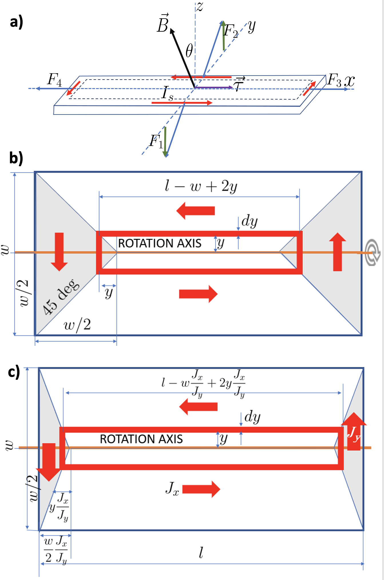
Torque is the twisting force that causes an object to rotate around an axis. Torque is the cross product of the force and the position vector connecting the point at which the torque is measured to the point where the force is applied.
is the torque vector and is the magnitude of the torque. is the force vector, and is the angle between the force vector and position vector.
Figure 1a illustrates the torque exerted on a rectangular REBCO sample with an induced circulating screening current , placed in a magnetic field tilted by an angle relative to the normal to the sample surface. This is the case when the magnetic field does not penetrate the sample. Screening currents flow only close to the edges and are sufficiently strong to screen the field inside the sample. It is evident that only the vertical components of the Lorentz forces and , contribute to the torque . The other components lie in the plane of the sample and cancel out each other, particularly the forces exerted on each side of the sample, where . Thus, if is perpendicular to the sample, torque vanishes. Figure 1b shows the distribution of the screening currents depicted as the critical current density, in a homogeneous, rectangular sample. This is the situation when the sample is fully penetrated by the magnetic field, and screening currents flow in the entire sample. A discussion of how to reach such a saturated state is presented in Section 3. The torque can be calculated by dividing these currents into elemental loops
After integration:
we get:
This can be rewritten as:
or
where
| (1) |
where is the magnetic moment, a ’coefficient’ between the torque and the magnetic field that characterizes current and its distribution in an object. The above equation defines the magnetic moment introduced when the first electrical motors were invented well before quantum mechanics, in which the magnetic moment plays a significant role. This derivation was first proposed by Gyorgy et al. [11].
Here, , , and are the film length, width, and thickness, respectively, and is the critical current density. The sample rotates about an axis perpendicular to and parallel to its longer side . This approach is valid when the critical current density is uniform. With , we can obtain from Eq. 1.
Figure 1 c illustrates a similar integration approach for the case when , that is, when (the current density across the sample) exceeds (the current density along the sample). In this case, the magnetic moment is expressed as:
| (2) |
This scenario arises when the sample is tilted around the rotation axis and the ’return’ currents at either sample end (shadowed in Fig. 1 do not fully experience the Lorentz force, thereby artificially increasing the observed moment. This is because only the region where the current flows along the rotation axis contributes to the torque and this region becomes larger. In certain samples, , notably in conductors grown on an inclined surface by THEVA [12]. This, in turn, reduces the observed . These effects are significantly mitigated if .
Typically we use mm and mm as these dimensions maintain the error below 10 % even for , as elaborated in [13].
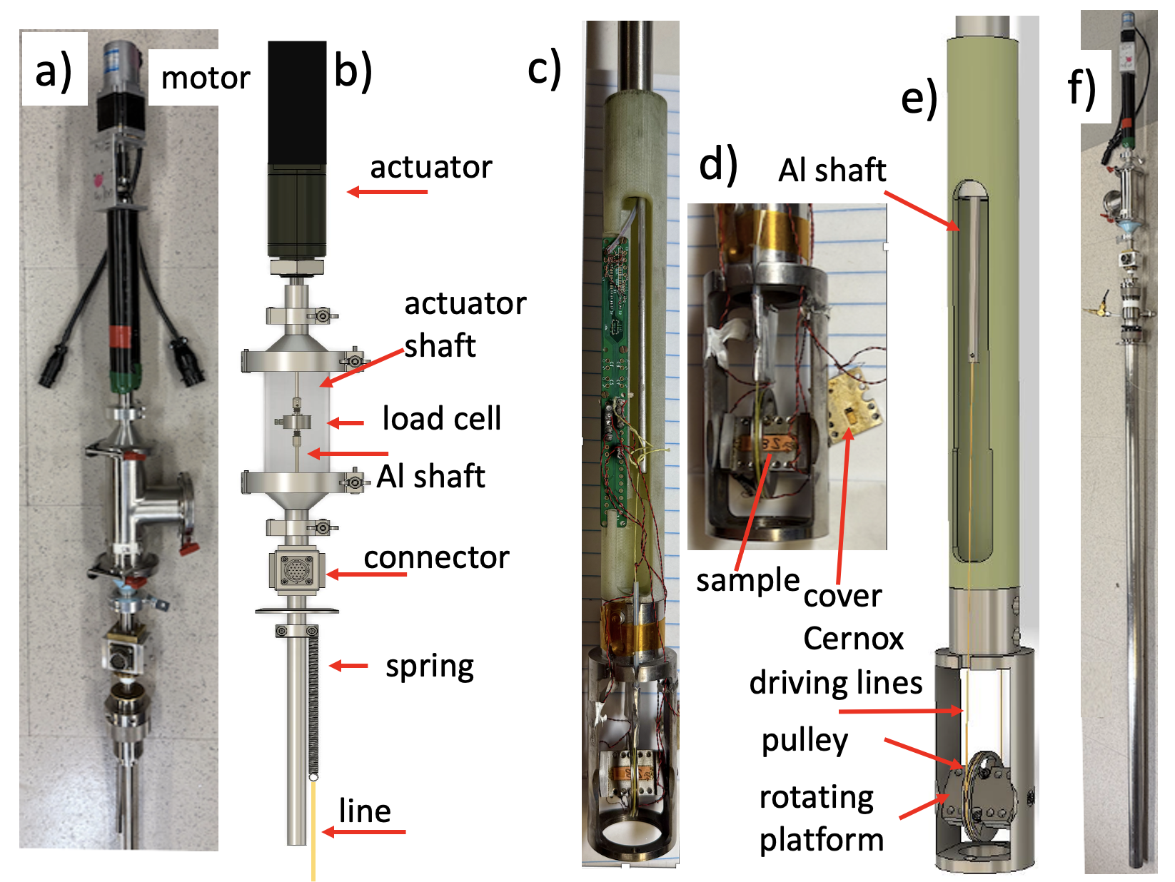
2 Design
The magnetometer is specially engineered for efficient assessment of the critical current in REBCO CC tapes as a function of the field, field angle, and temperature. It is also useful for studying other materials with strong magnetic moments and anisotropy, such as Nd magnets.
This system exhibits centrally located rotating sample platform within an external magnetic field. The platform is suspended by two Niva points anchored to a yoke complemented by two V-shaped sapphire jewels (Swiss Jewels) at its extremities. This design enables an almost frictionless rotation. A sample with dimensions of mm2 is positioned within a 100 m deep groove parallel to the rotation axis. It is then covered with a flat piece and fastened to the platform by using 0-80 screws. The sample platform, cover, and yoke are made from nonmagnetic polyamide (Meldin) or unalloyed titanium (grade 2).
Parallel to the rotating platform, a pickup coil detects the angle between the sample and external magnetic field. For precise temperature control, the Cernox thermometer is pressed into the sample. A resistive heater (3W surface mount resistor) of size mm3 is integrated onto the platform.
The rotation of the sample is enabled by a 28 mm-diameter titanium pulley attached to the platform, linked with two short fishing lines that slightly surpass the circumference of the spool. These lines are connected to two aluminum alloy (grade 6061) rods, each approximately 1.5 m in length and 3 mm in diameter. Aluminum was selected for its nonmagnetic properties because stainless steel was found to introduce significant forces owing to its inherent magnetism.
The first rod connects to a load cell (e.g., WMC Load Cell 22N from Interface Inc.), which is situated at room temperature, roughly 1.6 m from the center of the magnet. This cell is coupled with an actuator (from MDC Vacuum Products, Inc., Linear Motion FT, Standard, 4” Travel, Manual Drive) that offers a linear movement of 4 in. The actuator is driven by a servo-motor controlled by a computer. This mechanism allows the sample platform to achieve a rotation of up to 400 ∘. However, during the typical characterization, the sample is rotated between 210 ∘ and 240 ∘.
A single rotation of the actuator’s microscrew translates to a 1/40 inch linear movement, corresponding to a 2.72-degree rotation of the sample platform. A computer-controlled brushless servo motor drives the linear actuator at a wide range of speeds, from 0.01 to 2 ∘/s. The second aluminum rod is connected to a tensioning mechanism (a counterweight of G or a spring, G/inch), which balances the rotating platform.
The sample holder is placed at the field center of either a 52 mm bore 15 T superconducting magnet or a 31 T resistive magnet (with a 39 mm inner diameter cold bore). The sample rig (with a 39 mm outer diameter) can be placed in a long vacuum can with a regulated amount of helium exchange gas, or directly in liquid helium (LHe). The outer diameter of the magnetometer yoke is 1.25” (31.75 mm).
Measurements up to 45 T using the NHMFL hybrid magnet with a 16 mm bore are possible with a smaller probe. In such instances, the fishing lines are connected to a 10 mm diameter spool, leading to reduced precision in angle determination. Nevertheless, our apparatus remains compatible with the most powerful magnets and consistently ensures precise temperature control from 4.2 K to 50 K. The main features of the apparatus are shown in Figure 2.
3 Principle of operations
3.1 Field sweeps at fixed angle
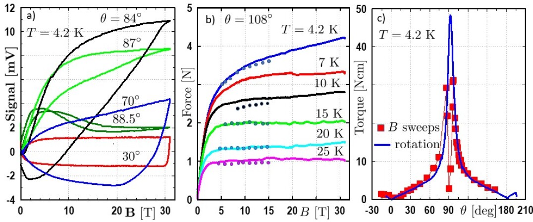
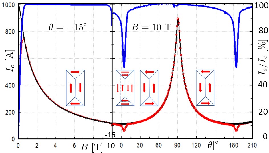
Figure 3a shows the experimental data of the load cell signal obtained by sweeping the field when the angle is fixed. These loops illustrate the screening current behavior, indicating that current reversal differs based on the angle of the sample relative to the magnetic field. It is clear that for small angles () the signal shows a full loop; however, for higher angles (), a sweep from 30 to 20 T is required to reverse the screening current in the sample. Closer to the ab plane, it is impossible to observe a full hysteresis loop.
Figure 3b shows the force applied to the load cell by a 144 mm2 REBCO sample tilted in the magnetic field (18∘ away from the ab-plane of the sample) at various temperatures. These values are derived from hysteresis curves and are represented by solid lines. The symbols indicate the pinning forces derived from transport measurements [14]. These forces should be proportional (as both are proportional to ); indeed, after multiplying pinning force by a factor of approximately 1/400 a good agreement is observed. The only exception are the data for K, where the sample transport measurement is apparently overheated. We chose this comparison of raw data (force) from NIST calibrated load cell to validate our method without recalculating to using Eq. 1 that contains some geometrical factors. This comparison validates torque magnetometry as a valuable and complementary tool to transport measurements. It is worth highlighting that this torque measurement was executed in merely two hours with 10 T/min field sweeps, using only 5 liters of LHe and 10 MWh of energy for the resistive magnet’s power. This efficiency reduces resource usage by a factor of 20 compared to the 4-probe transport technique to achieve an equivalent measurement.
The torque exerted on a typical sample as a function of the angle (measurements performed in LHe and at very high magnetic fields T), shown in Figure 3c, also illustrates the significant magnitude of the forces arising within a REBCO magnet. A 5 Ncm torque on a 28 mm diameter rotator pulley corresponds to a 35 N force exerted on the 4 mm wide sample edge.
A particularly notable aspect of the torque profile, derived from field sweeps as shown in Fig. 3c, is its reduction near the ab plane (). The torque vanishes at the ab plane, whereas it is well established that exhibits a maximum at this angle, as documented in [15, 16]. This discrepancy arises primarily because the perpendicular component of the field, T, vanishes when is parallel to the ab-plane. Near the ab plane, is small, and a high leads to strong screening currents, which prevent the formation of a fully saturated critical state. Essentially, the critical current is sufficiently large to entirely shield a section of the sample.
Various other factors can also affect the torque in this region. In nonideally flat HTS films, the angle has a distribution that can lead to the generation of opposing current loops around . Although their contribution to the torque is always positive (according to Lenz’s law), these loops would broaden the maximum. Interestingly, this widening is not detrimental to the magnet performance.
Additionally, when is parallel to the ab-plane, a fully critical state can form through currents flowing parallel to the sample’s length in the ab-plane and parallel to the c-axis, that is, through the film’s thickness [17]. However, since in REBCO CC, the moment generated by such currents would be three orders of magnitude lower than those in the ab-plane, as demonstrated by Eq. 1. Furthermore, this moment aligns with the in-plane component of the magnetic field, resulting in a zero torque.
In any case, a fully penetrated saturated state cannot be achieved by field sweeps around . Moreover, when the field sweep changes direction, the screening currents also reverse. For angles close to , a substantial amount of field change is required to reverse the currents across the entire sample. Near the ab plane, even field sweeps ranging from -30 to 30 T cannot induce a critical state in the sample. This makes the field sweeps at a fixed angle ineffective for characterizing CCs when the magnetic field is nearly parallel to the ab plane.
Despite making assessment impossible, low screening currents and torques around are beneficial for magnet performance.
3.2 Rotation at fixed magnetic field
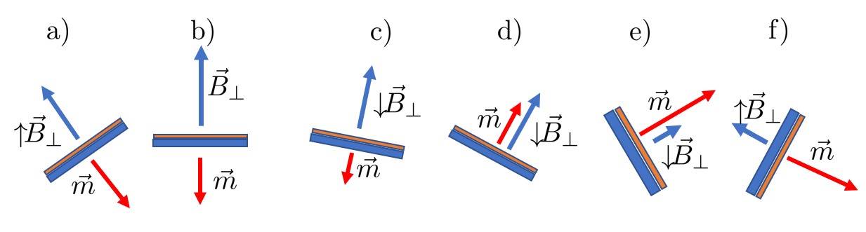
First, the angle is set to , and the field is ramped up to a value typically between 5 and 30 (45) T. The perpendicular component of the field relative to the sample reaches . The change in flux through the sample, given by , where is the surface area of the sample, induces screening currents and a magnetic moment opposite to to conserve the flux.
The sample is then rotated clockwise. As increases, the magnetic moment remains the opposite to . However, when the sample passes through , begins to decrease, causing the screening currents to gradually reverse and the direction of to align with . As the sample continues rotating, the magnetic moment increases as increases while approaches 90∘. At , reaches zero and then reverses its direction in the coordinate system of the sample. However, the direction of does not change relative to the sample, and it remains opposite to increasing . Therefore, no reversal of the screening currents occurs when rotates through the ab plane. This key feature of the method allows the assessment of near the ab plane.
In essence, this process is quite similar to that of an AC electric generator, which produces the maximum voltage (and current) when the field is in the plane of the windings, whereas the voltage reaches zero when is perpendicular to the windings. To maintain the rotation of the sample, the torque must remain positive, except when , where the torque vanishes as .
The magnetic flux through a sample of surface is:
| (3) |
Differentiating, we find:
| (4) |
For both fixed field and sample surface:
| (5) |
When rotating the sample in a constant field :
| (6) |
This results in T for T with and . This is sufficient to induce a fully critical state.
In Fig. 3c, the magnetic moment of the sample, measured during rotation at T (represented by the solid line), is displayed alongside the data derived from field sweeps (denoted by symbols). Indeed, the rotation data exhibits a pronounced peak around the ab plane, which aligns with expectations and the above considerations.
Moreover, the electric field generated by sample rotation is quite comparable to that employed during transport measurements. For a sample rotating at constant angular speed :
| (7) |
where is time and mm is the sample circumference. For a rotation of one degree per second ( rad/s), when T rotates through the ab plane, this yields approximately 7 V/cm at the edge of the sample. This value is similar to the electric field criteria used in the transport measurements. It changes with , , and the angle. However, for typical values, the induced current:
| (8) |
barely depends on these parameters. Indeed, the rotation speed would need to be changed by at least a factor of ten to observe a 4 % signal difference. This is another fortunate feature that makes the method useful and an appropriate substitute for the transport current measurements preferred by skeptical magnet builders.
3.3 Numerical model
Measuring the critical current by way of torque relies on the assumption that above the saturation field screening current runs in the entire sample at . We modeled the case of a REBCO tape sample in a rotating background field and calculated the total screening current contribution in relation to the calculated critical current. Our model utilizes 2D based on a model similar to that developed for axisymmetric solenoids [18]. The effect of rotation has been investigated previously for the purpose of the screening current-induced field (SCIF), strain, and changes in mutual inductance. [19, 20, 21]. We included rotation by changing the surrounding background magnetic field.
The critical current is modeled by the Kim fit with corresponding parameters
| (9) |
where A/cm2, , T, and , and we include the power law of the superconducting resistivity:
| (10) |
with V/cm and . HTS film thickness , total tape thickness , and tape width mm.
In Fig.5 we plot the screening currents, critical current and saturation as , , and , where the screening current is calculated for half of the sample (hence 1/2).
The background field is initially ramped from zero to 10 T while keeping the sample at . As shown in the left panel of Fig.5, the screening current reaches the value of the critical current at approximately T. For fields above this value, their ratio remains equal to one.
After the field sweep stops, the sample rotates at a fixed field with a speed of 1 ∘/s, as illustrated in the right panel of Fig. 5. As the field rotates around the c-axis, the screening currents begin to reverse, as shown in the insets. Around , this reversal process concludes, and approaches . In the range , they remain virtually equal, with higher than 98 %. In other words, the screening currents are approximately equivalent to the critical current. Although assessing beyond this range introduces some error, the region around the ab plane is of primary interest for magnet design and is challenging to access with transport methods.
3.4 Torque measurements when sample rotates
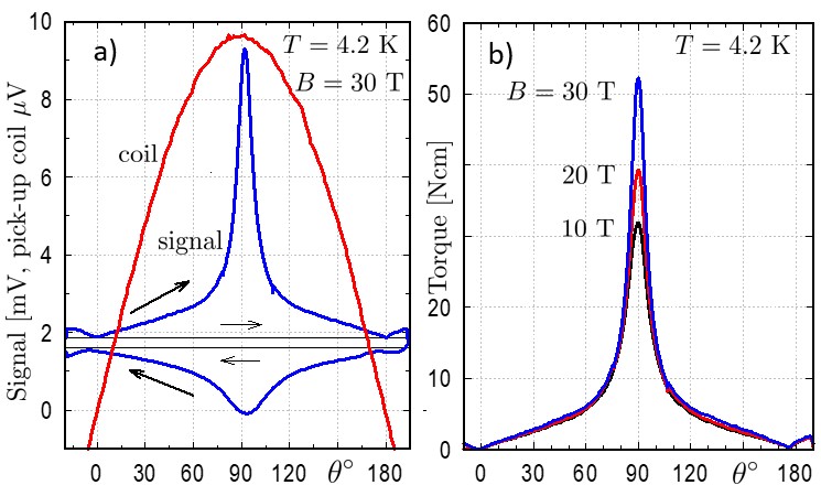
Figure 6a shows forces determined by the load cell when the sample is rotated from to 210∘ and back at T. Horizontal lines go through the points where the torque vanishes, that is, when c axis at for the forward and back rotation, respectively. These values are subtracted from the total signal to determine the torque of the sample. It is very important that these base lines can be determined at two (or more) points every time the field crosses the c axis where the torque is zero. This allows sweeping of the angle in only one direction. This is in contrast with the sweeping field at a fixed angle. When the field is swept, there is only one point at where the torque vanishes. The total signal contains the force from the sample torque , from the balance that tensions the fishing lines , and some residual friction .
Figure 6a also shows the signal from the pickup coil, which allows the angle to be determined. Figure 6b shows the torque ( where is the radius of rotator pulley) vs. the angle for different after subtraction.
Significantly, the torque vanishes at and , which is not when the field is perpendicular to the plane of the sample, but when it is perpendicular to the crystallographic ab plane of the sample. In addition, the ab peak is shifted to the right to . This shift stems from the fact that the ab plane is tilted by a few degrees, because REBCO is grown on tilted substrates. Torque measurements can be used to identify the tilt direction in a given sample. This identification is not possible by transport measurements performed around the c axis because the has a rather smooth minimum (or maximum at elevated temperatures) at this angle, which does not necessarily correspond to the crystallographic direction. However, the tilt can be identified by transport measurements from the sharp maximum that appears around the ab plane. However, as previously mentioned, transport measurements in this region are extremely difficult because of the very high critical currents carried by the CCs in this configuration.
4 Experimental results
4.1 Critical current assessment up to 45 T.
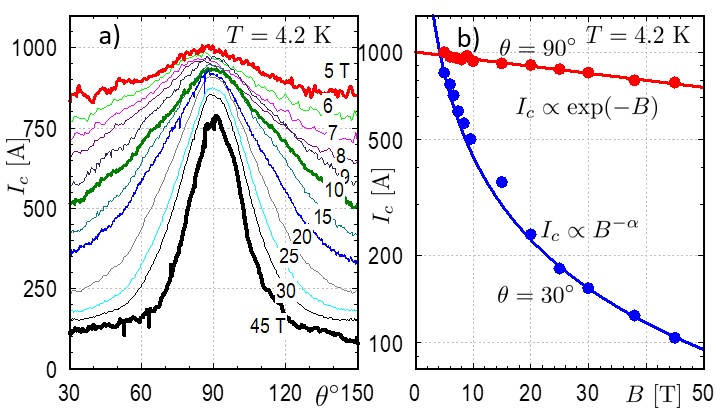
Figure 7a shows the angular critical current assessed in a sample at several fields ranging from 5 T to 45 T. Because of the small diameter of the space (16 mm), measurements in the 45 T hybrid magnet are made using a different probe with a smaller rotator pulley. This increases the noise and angle reading error. Figure 7b shows measured at the ab plane and the c axis. The solid lines show the fits to the exponential and power functions, respectively. It is clearly seen, that at K there is no obvious change in behavior at high fields up to 45 T. These findings suggest that REBCO tapes maintain a strong performance even under extreme magnetic fields, which is crucial for their use in future applications.
4.2 Characterization of modern REBCO CC tapes.
Figure 8a shows assessed with torque in several production samples with 15 % BZO from SuperPower Inc. at T and K. The samples have quite different magnitudes of , ranging from 700 to 2000 A at the ab plane. This variability makes it possible to select an appropriate conductor for a given application. In addition, all conductors have wide ab plane maxima with a full-width at half-maximum (FWHM) of approximately . These maxima are accompanied by shallow minima at and . These minima are a consequence of the weak and wide maxima around the c axis. It is well known that in BZO -doped samples, strong pinning to BZrO3 (BZO) nanorods dominates at high temperatures, leading to a pronounced maxima at the c axis. Because of the high BZO content, they are still observed at low temperatures. This leads to a relatively low anisotropy, which is beneficial for both magnet and cable applications. Figure 8b compares the REBCO tapes of different formulations and manufacturers. Significant differences between the ab plane maxima are clearly seen, from for non-BZO formulation to in the R&D 15 % sample. It is also seen that in non-BZO samples, decreases all the way from the ab-plane to the c-axis while it is flat beyond and at 7.5 % doping and increases there for 15 % doping. In general, the above results show that modern, heavily doped samples show very broad ab peaks and much lower anisotropy, both of which are beneficial for magnet construction.
4.3 Lengthwise fluctuations
REBCO CC are known to exhibit non-uniformity along their length and width. The lengthwise variation in the critical current , where is the position on the tape, can be measured relatively easily at 77 K using transport and remnant magnetization techniques [22, 23]. Commercial devices, such as tapestars, are available for assessing . Over the years, the standard deviation of relative changes has decreased from approximately 10% to 2-3% in tapes from certain manufacturers. For older conductors, the variations were mainly due to changes in the cross-section of the REBCO film. In newer conductors with more stable cross-sections, variations in the pinning landscape along the tape dominate . These originate from an unstable production process, such as fluctuations in temperature during deposition. In practice any production step can contribute to such inhomogeneities.
Characterization at higher temperatures (65-77 K) can not be accurately extrapolated to lower temperatures owing to different pinning mechanisms. At temperatures above K correlated pinning by sparser microstructures as insulating pins such as BaZrO3 or RE2O3 dominates, while at lower temperatures, weak but dense pinning centers add equivalent and isotropic pinning [24]. Scaling from 77 K to 4.2 K introduces an uncertainty of over 60% [25]. Currently, no instrumentation can perform continuous lengthwise measurements at low temperatures.
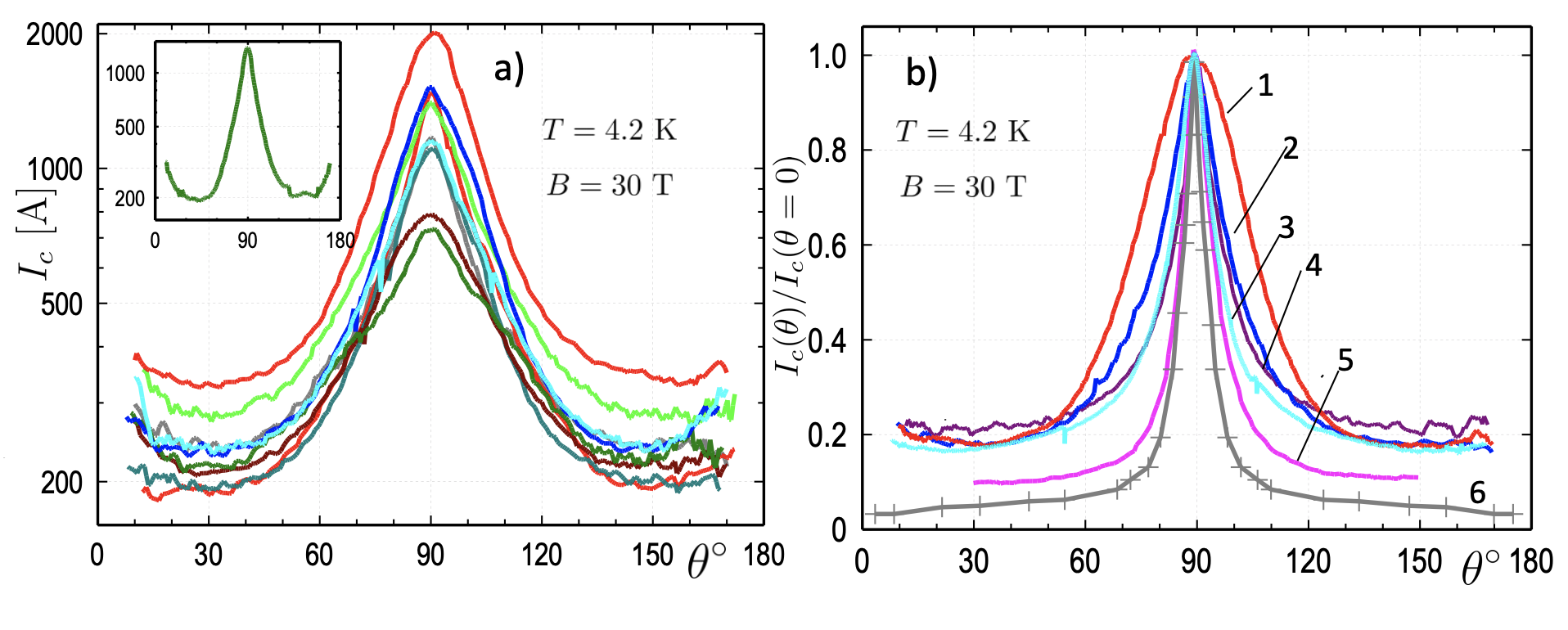
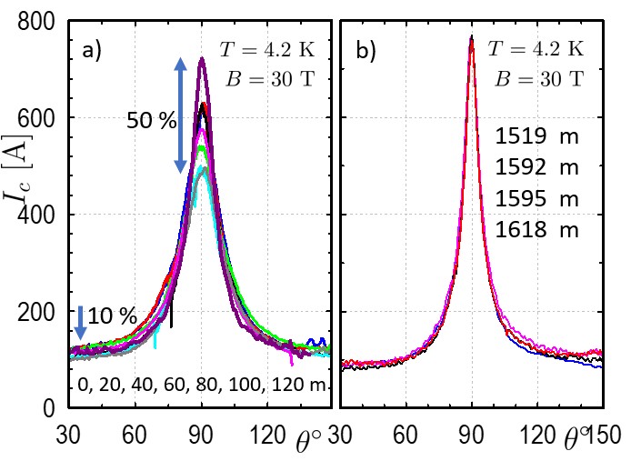
Our results, obtained from short samples cut from long-length tapes, show significant variation within the same tape. Figure 9a shows the angular measured for several short samples cut every 20 m from the original tape. It is evident that the angular measurements differ considerably near the plane. At , differences can reach up to 50%, whereas at , the differences decrease to approximately 10%. Figure 9b shows values of the four samples cut from another tape. Although these samples were cut at larger distances, traces overlap with accuracy of line thicknesses in Figure 9b. The two tapes were manufactured with the same specifications; however, the homogeneous tape was cut from the center of a 12 mm wide production tape, whereas the tape with strong lengthwise variations was cut from the edge. The edge, which is not centrally positioned during growth, exhibits poor homogeneity. This observation is confirmed in three other tapes and suggests that variations stem from issues with growth near the edge. However, further studies are required to confirm this hypothesis.
4.4 Flux jumps
During torque measurements, a significant tendency for flux jumps is observed in certain REBCO conductors. Flux jumps in type-II superconductors stem from the fact that the stationary penetrating field distribution depends on energy dissipating screening currents, with strongly dependent on and and strong non-linearity. This leads to a fragile non-equilibrium state, and if the heat produced by the current is not effectively removed, thermomagnetic instability occurs. This instability leads to a sudden vortex redistribution and associated heating which can catastrophically drive the conductor normal [26, 27].
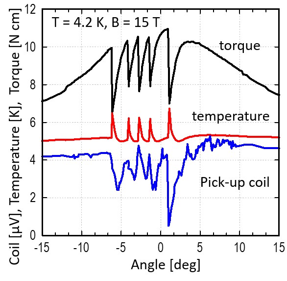
Figure 10 illustrates the torque, temperature, and voltage from the pick-up coil measured as the sample is rotated in an external magnetic field ( ) T at a speed of 0.1∘/s. Flux jumps manifest as sudden drops in the torque during sample rotation, accompanied by noticeable temperature increases of up to 7 K, as measured by a Cernox thermometer. The actual temperature increase in the sample is likely to be much higher. The flux jumps are also directly observed via the pick-up coil, whose primary purpose is to measure the sample angle, but it also clearly picks up the sample flux changes as well. The lowest trace in the figure shows a significant decrease in the signal from the pickup coil at the beginning of each flux jump, indicating a sudden reduction in the screening currents in the sample.
A systematic study of this phenomenon across various REBCO-coated conductors from different manufacturers led to several important conclusions, as summarized in Table 1. Flux jumps occur more frequently in samples with thicker REBCO films. For instance, they are consistently observed in 5 m thick samples at 4.2 K and even above 20 K. They occur in 3 m thick samples at 4.2 K but not at 20 K. In contrast, 1 m thick samples do not exhibit flux jumps at any . Thicker samples generally carry higher currents, which increases losses and exacerbates thermal instability. Additionally, it is well known [28, 29] that the quench velocity is inversely proportional to the sample dimensions. The frequency of flux jumps also increases with the rotation speed of the sample stage; they are present in 5 m samples even at the slowest rotation rate (0.01∘/s). This suggests that manufacturing tapes with thick REBCO films may not be the best way to increase the entire tape current density, especially for devices operating at lower temperatures. For thinner samples, flux jumps occur only at faster rotation speeds, such as 1∘/s.
| Samples | Flux jumps? | thickness [m] | rotation speed ∘/s | [A] at 15 T |
| A (many) | always at 4.2 K and 20 K | 5.0 | 0.0125 | 6000 |
| B (many) | always at 4.2 K never at 20 K | 0.125 | 900 | |
| C | always at 4.2 K | 0.0125 | 1080 | |
| D (many) | often at 4.2 K | 1.8 | 0.1 | 2000 |
| E (many) | sporadically at 4.2 K | 1.8 | 0.5 | 900 |
| F | sporadically at 4.2 K | 1.57 | 0.25 | 2000 |
| G | sporadically at 4.2 K | 1.4 | 0.25 | 1500 |
| H | never | 1.12 | 1 | 1800 |
In REBCO CC, flux jumps are more likely to be observed in high magnetic fields, in contrast to low-temperature superconductors such as Nb3Sn. Specifically, critical current of REBCO decays very slowly with an increasing field around the plane: . With a typical T, decreases slower than increases, showing only a 40% decrease between 5 and 30 T. Consequently, the Lorentz forces increase with a field up to 45 T, which is the highest field used, promoting instability. Improving the heat sink, such as using a thicker copper stabilizer or measuring in liquid helium instead of helium exchange gas, helps suppress these jumps, highlighting the well known connection between flux jumps and thermal instability.
Rotating REBCO CC in a magnetic field leads to extreme conditions where the screening currents are fully saturated near the ab plane, where both and the external magnetic field flux change reach their maximum values. So far, flux jumps have not been observed when the magnetic field is swept while the sample remains at a fixed angle, even at a maximum sweep rate of 10 T/min. This absence may be because the screening currents near the ab plane are significantly lower because they occupy only the edge of the conductor in a not fully penetrated state, as discussed earlier. However, recent studies have shown flux jumps in REBCO stacks [30] when the perpendicular field is swept. Flux jumps remain a critical concern for magnet design, even if the tape in the magnets is not explicitly rotated. Moreover, reports [19] indicate that despite reinforcements, REBCO tapes in magnets can experience rotation under strong torques induced by screening currents. If this rotation involves a stick-slip movement, it can cause sudden changes in the tape angle (large ) which may trigger flux jumps.
Although the thermomagnetic instability associated with flux jumps has been extensively researched for its theoretical interest, it remains an undesirable phenomenon from an application perspective. The effective management and mitigation of flux jumps are crucial for the stability and performance of superconducting devices. Although flux jumps have been studied in various superconductors, including crystalline YBCO [31, 32], reports specifically on REBCO-coated conductors are relatively rare [33, 29, 34]. This rarity may stem from the belief that REBCO operates at temperatures significantly below , making flux jumps expected to be infrequent. However, a phenomenally high at low temperatures can trigger flux jumps even when it is well below .
The observed flux jumps at high fields indicate a potential thermal instability, which could limit the performance of superconducting magnets in real-world applications. Future efforts should focus on mitigating these instabilities through on one hand enhanced pinning mechanisms, and on applying better conductor thermal stabilization.
5 Summary
This study demonstrates that torque magnetometry is a powerful tool for evaluating the performance of REBCO tapes, particularly under extreme conditions of extremely high fields and angles near the ab plane. Approximately 300 different conductors have been assessed at magnetic fields of up to 30 T and beyond. Our findings demonstrate that torque magnetometry is a robust technique for assessing critical current and its lengthwise fluctuations, offering a path toward improving the design of superconducting magnets. REBCO tapes with different doping formulations exhibited distinct angular critical current behaviors, which are important for magnet design. Lengthwise variations in the critical current were observed, with tapes cut from the edges of production tapes showing larger variability than those cut from the center. These variations are significantly stronger when is parallel to the ab plane. The magnetometer identified flux jumps in the samples with thick REBCO layers, which are linked to thermal instabilities. This strongly suggests that, instead of increasing thickness of REBCO and reducing the stabilizer thickness, an enhancement of pinning is preferable to increase the technical critical current density. In conclusion, this study provides a new and efficient way to characterize 2G HTS tapes, offering insights that are critical for the development of high-field magnets and superconducting technologies.
References
References
- [1] H. W. Weijers, W. D. Markiewicz, A. J. Voran, S. R. Gundlach, W. R. Sheppard, B. Jarvis, Z. L. Johnson, P. D. Noyes, J. Lu, H. Kandel, H. Bai, A. V. Gavrilin, Y. L. Viouchkov, D. C. Larbalestier, and D. V. Abraimov. Progress in the Development of a Superconducting 32 T Magnet With REBCO High Field Coils. IEEE TRANSACTIONS ON APPLIED SUPERCONDUCTIVITY, 24(3), JUN 2014.
- [2] Jianhua Liu, Qiuliang Wang, Lang Qin, Benzhe Zhou, Kangshuai Wang, Yaohui Wang, Lei Wang, Zili Zhang, Yinming Dai, Hui Liu, Xinning Hu, Hui Wang, Chunyan Cui, Dangui Wang, Hao Wang, Jinshui Sun, Wanshuo Sun, and Ling Xiong. World record 32.35tesla direct-current magnetic field generated with an all-superconducting magnet. SUPERCONDUCTOR SCIENCE & TECHNOLOGY, 33(3), MAR 2020.
- [3] Patrick Wikus, Wolfgang Frantz, Rainer Kuemmerle, and Patrik Vonlanthen. Commercial gigahertz-class nmr magnets. SUPERCONDUCTOR SCIENCE & TECHNOLOGY, 35(3), MAR 1 2022.
- [4] Seungyong Hahn, Kwanglok Kim, Kwangmin Kim, Xinbo Hu, Thomas Painter, Iain Dixon, Seokho Kim, Kabindra R. Bhattarai, So Noguchi, Jan Jaroszynski, and David C. Larbalestier. 45.5-tesla direct-current magnetic field generated with a high-temperature superconducting magnet. NATURE, 570(7762):496+, JUN 27 2019.
- [5] see, e.g., J. van Nugteren, G. Kirby, J. Murtomäki, G. DeRijk, L. Rossi, and A. Stenvall. Toward rebco 20 t+ dipoles for accelerators. IEEE Transactions on Applied Superconductivity, 28(4):1–9, June 2018.
- [6] D Uglietti. A review of commercial high temperature superconducting materials for large magnets: from wires and tapes to cables and conductors. Superconductor Science and Technology, 32(5):053001, apr 2019.
- [7] Alexander Molodyk and David C. Larbalestier. The prospects of high-temperature superconductors. SCIENCE, 380(6651):1220–1222, JUN 2023.
- [8] J. Jaroszynski, A-M Constantinescu, G. Miller, A. Xu, A. Francis, T. Murphy, and D. C. Larbalestier. Rapid assessment of rebco cc angular critical current density j(c)(b, t=4.2 k, theta) using torque magnetometry up to at least 30 tesla. SUPERCONDUCTOR SCIENCE & TECHNOLOGY, 35, 2022.
- [9] J. Jaroszynski, A-M Constantinescu, G. Miller, and D. C. Larbalestier. Magnetometer for large magnetic moments with strong magnetic anisotropy, 2024. US Patent No. 12,181,540.
- [10] J. Lu, E. S. Choi, H. Kandel, D. V. Abraimov, and W. D. Markiewicz. Hysteresis Loss of REBCO Conductor Up to 35 T. IEEE TRANSACTIONS ON APPLIED SUPERCONDUCTIVITY, 24(3), JUN 2014.
- [11] E M Gyorgy, R B Vandover, K A Jackson, L F Schneemeyer, and J V Waszczak. . Appl. Phys. Lett. , 55:283–5, 1989.
- [12] W Prusseit, R Nemetschek, C Hoffmann, G Sigl, A Lümkemann, and H Kinder. Isd process development for coated conductors. PHYSICA C-SUPERCONDUCTIVITY AND ITS APPLICATIONS, 426(2):866–871, OCT 1 2005. 17th International Symposium on Superconductivity (ISS 2004), Niigata, JAPAN, NOV 23-25, 2004.
- [13] J R Thompson, J W Sinclair, D K Christen, Yifei Zhang, Y L Zuev, C Cantoni, Yimin Chen, and V Selvamanickam. Field, temperature, and angle dependent critical current in coated conductors obtained via contact-free methods. Superconductor Science and Technology, 23:014002, 2009.
- [14] Ashleigh Francis, D. Abraimov, Y. Viouchkov, Y. Su, F. Kametani, and D. C. Larbalestier. Development of general expressions for the temperature and magnetic field dependence of the critical current density in coated conductors with variable properties. SUPERCONDUCTOR SCIENCE & TECHNOLOGY, 33(4), APR 2020.
- [15] D. Uglietti, H. Kitaguchi, S. Choi, and T. Kiyoshi. Angular dependence of critical current in coated conductors at 4.2 k and magnet design. IEEE Transactions on Applied Superconductivity, 19(3):2909–2912, 2009.
- [16] A. Xu, J. J. Jaroszynski, F. Kametani, Z. Chen, D. C. Larbalestier, Y. L. Viouchkov, Y. Chen, Y. Xie, and V. Selvamanickam. Angular dependence of J(c) for YBCO coated conductors at low temperature and very high magnetic fields. SUPERCONDUCTOR SCIENCE & TECHNOLOGY, 23(1), JAN 2010.
- [17] A. A. Zhukov, G. K. Perkins, Yu. V. Bugoslavsky, and A. D. Caplin. Geometrical locking of the irreversible magnetic moment to the normal of a thin-plate superconductor. Phys. Rev. B, 56:2809–2819, Aug 1997.
- [18] Edgar Berrospe-Juarez, Victor M. R. Zermeno, Frederic Trillaud, and Francesco Grilli. Real-time simulation of large-scale hts systems: multi-scale and homogeneous models using the ¡i¿t¡/i¿-¡i¿a¡/i¿ formulation. SUPERCONDUCTOR SCIENCE & TECHNOLOGY, 32(6), JUN 2019.
- [19] D. Kolb-Bond, M. Bird, I. R. Dixon, T. Painter, J. Lu, K. L. Kim, K. M. Kim, R. Walsh, and F. Grilli. Screening current rotation effects: Scif and strain in rebco magnets. SUPERCONDUCTOR SCIENCE & TECHNOLOGY, 34(9), SEP 2021.
- [20] Yufan Yan, Yi Li, and Timing Qu. Screening current induced magnetic field and stress in ultra-high-field magnets using rebco coated conductors. SUPERCONDUCTOR SCIENCE & TECHNOLOGY, 35(1), JAN 2022.
- [21] So Noguchi, Takanobu Mato, Kwangmin Kim, and Seungyong Hahn. Electromagnetic behavior simulation of rebco pancake coils considering rebco tape rotation under high magnetic field. IEEE TRANSACTIONS ON APPLIED SUPERCONDUCTIVITY, 33(5), AUG 2023.
- [22] Xinbo Hu, Lidia Rossi, Alexander Stangl, John Willam Sinclair, Fumitake Kametani, Dmytro Abraimov, Anatolii Polyanskii, James Y. Coulter, Jan Jaroszynski, and David C. Larbalestier. An Experimental and Analytical Study of Periodic and Aperiodic Fluctuations in the Critical Current of Long Coated Conductors. IEEE Transactions on Applied Superconductivity, 27, 2017.
- [23] L. Rossi, X. Hu, F. Kametani, D. Abraimov, A. Polyanskii, J. Jaroszynski, and D. C. Larbalestier. Sample and length-dependent variability of 77 and 4.2K properties in nominally identical RE123 coated conductors. SUPERCONDUCTOR SCIENCE & TECHNOLOGY, 29, 2016.
- [24] A. Xu, V. Braccini, J. Jaroszynski, Y. Xin, and D. C. Larbalestier. Role of weak uncorrelated pinning introduced by BaZrO3 nanorods at low-temperature in (Y,Gd)Ba2Cu3Ox thin films. PHYSICAL REVIEW B, 86(11), SEP 13 2012.
- [25] V. Braccini, A. Xu, J. Jaroszynski, Y. Xin, D. C. Larbalestier, Y. Chen, G. Carota, J. Dackow, I. Kesgin, Y. Yao, A. Guevara, T. Shi, and V. Selvamanickam. Properties of recent IBAD-MOCVD coated conductors relevant to their high field, low temperature magnet use. SUPERCONDUCTOR SCIENCE & TECHNOLOGY, 24(3), MAR 2011.
- [26] RG Mints and EH Brandt. Flux jumping in thin films. PHYSICAL REVIEW B, 54(17):12421–12426, NOV 1 1996.
- [27] M.N. Wilson. Superconducting Magnets. Oxford Univ. Press, Oxford, 1983.
- [28] WERTHEIM.MR and GILCHRIS.JG. Flux jumps in type 2 superconductors. JOURNAL OF PHYSICS AND CHEMISTRY OF SOLIDS, 28(12):2509–&, 1967.
- [29] U Bolz, B Biehler, D Schmidt, BU Runge, and P Leiderer. Dynamics of the dendritic flux instability in ybacuo. EUROPHYSICS LETTERS, 64(4):517–523, NOV 2003.
- [30] T. Garg, J. Jaroszynski, E.S. Choi, M.D. Sumption, M. Majoros, and E.W. Collings. Magnetization in rebco based cables in b- fields up to 30 t for accelerator applications, 2024. to be published.
- [31] AP Hope, MJ Naughton, DA Gajewski, and MB Maple. Flux jump avalanches in torque studies of single crystal ybacuo. PHYSICA C, 320(3-4):147–153, JUL 20 1999.
- [32] Viktor Chabanenko, Adam Nabialek, Roman Puzniak, Olena Kuchuk, Oleksandr Chumak, Felipe Perez-Rodriguez, Umapada Pal, Valentin Garcia-Vazquez, Raul Cortes-Maldonado, Jun Qian, Xin Yao, and Henryk Szymczak. Magnetic moment inversion at giant flux jump: dynamical property of critical state in type-ii superconductors. SCIENTIFIC REPORTS, 9, APR 17 2019.
- [33] VV Chabanenko, IB Krynetskii, S Piechota, and H Szymczak. Giant magnetostriction and flux instabilities in textured ybacuo plates. PHYSICA B, 216(3-4):289–290, JAN 1996. International Workshop on Advances in High Magnetic Fields (AHMF 95), NATL RES INST MET, TSUKUBA, JAPAN, FEB 20-22, 1995.
- [34] I. A. Kovalev, S. L. Kruglov, A. Polyakov, V, D. Shutova, I, and V. Shcherbakov, I. Thermomagnetic stability and current-carrying capacity of rebco tapes without copper coating at 4.2 k. TECHNICAL PHYSICS, 66(10):1123–1130, OCT 2021.