Unveiling the Potential of iMarkers: Invisible Fiducial Markers for Advanced Robotics
Abstract
Fiducial markers are widely used in various robotics tasks, facilitating enhanced navigation, object recognition, and scene understanding. Despite their advantages for robots and Augmented Reality (AR) applications, they often disrupt the visual aesthetics of environments because they are visible to humans, making them unsuitable for non-intrusive use cases. To address this gap, this paper presents “iMarkers”—innovative, unobtrusive fiducial markers detectable exclusively by robots equipped with specialized sensors. These markers offer high flexibility in production, allowing customization of their visibility range and encoding algorithms to suit various demands. The paper also introduces the hardware designs and software algorithms developed for detecting iMarkers, highlighting their adaptability and robustness in detection and recognition stages. Various evaluations have demonstrated the effectiveness of iMarkers compared to conventional (printed) and blended fiducial markers and confirmed their applicability in diverse robotics scenarios.
1 Introduction
Fiducial markers, i.e., artificial landmarks with distinguishable visual patterns, can bring the high potential for various applications where data encoding replaces costly data streaming processes [1]. As markers provide better-defined reference points than the naturally available ones, they are “simple-yet-effective” solutions where reliable feature-matching and pose information extraction are essential. Augmenting information in markers placed on environments and employing proper systems to extract them can benefit a wide range of cases, including Augmented Reality (AR), Mixed Reality (MR), and robotics tasks [2]. Markers can narrow down the range of objects a robot needs to recognize and provide real-time pose information for tracking and localization. For instance, decoding data from detected markers using the robot’s camera is less costly than processing the entire visual scene.
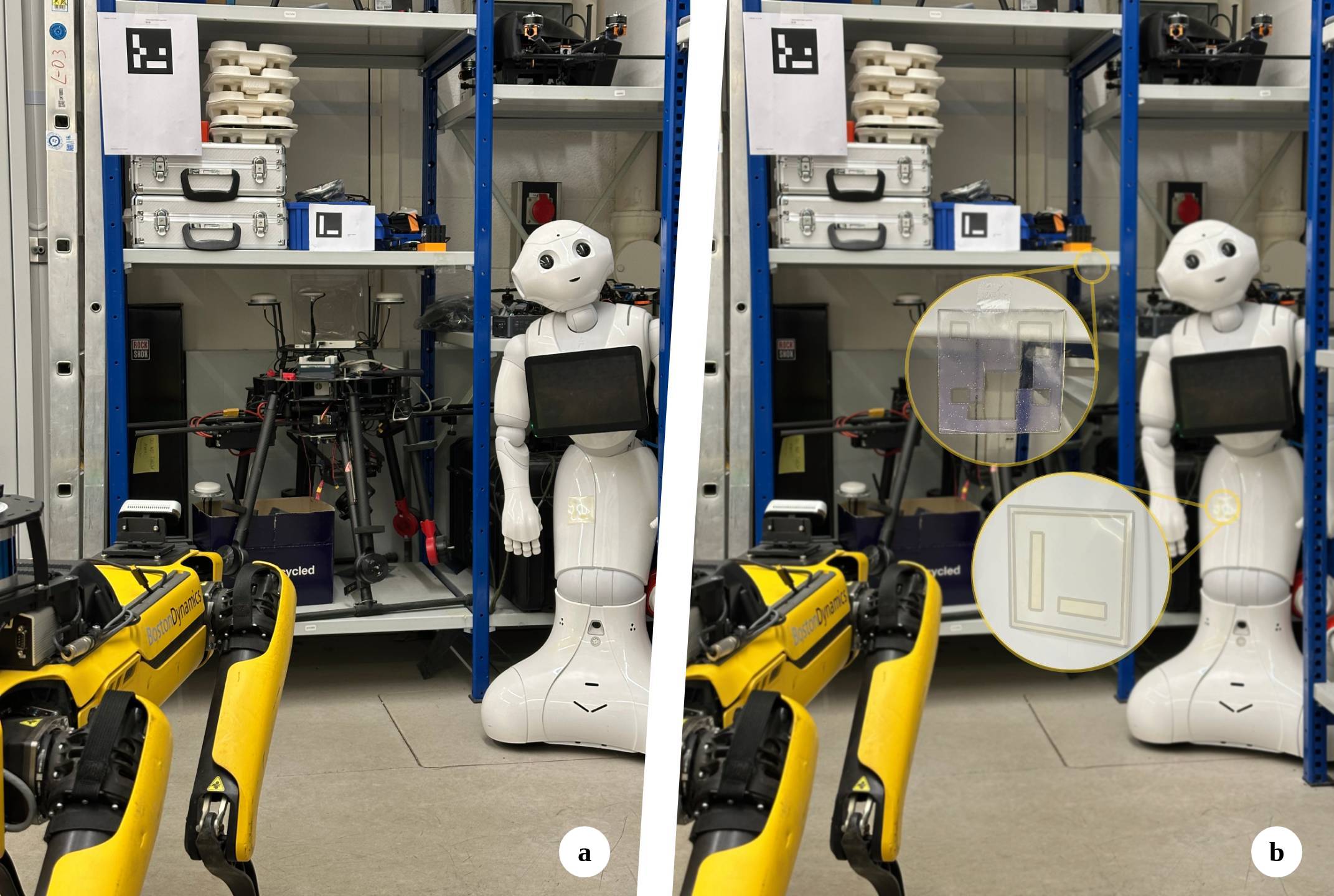
Although such markers can convey various advantages in robotics, seeing multiple objects labeled with printed binary-color markers can be aesthetically undesirable and destructive. In other words, many would want to avoid seeing printed tags around them and prefer that the robots operate well without spoiling zones with these artificial landmarks. Moreover, evidence has shown visible markers can disrupt and interrupt natural gaze behaviors [3]. Consequently, and as a part of an interdisciplinary project, the authors worked on the idea of employing Cholesteric Spherical Reflectors developed by the team to produce a new generation of fiducial markers [4], dubbed iMarker111https://snt-arg.github.io/iMarkers/. This can be done by replacing the printer inks for printing common fiducial markers with spherical shells of CSRs. Due to the peculiar behavior of CSRs, iMarkers can be invisible (indistinguishable) to human eyes but observable by robots in case a dedicated sensor is provided [5]. Moreover, such markers can be fabricated to be detected only in specific wavelength ranges of light to avoid visual clutter in the environment. The iMarker concept is illustrated in Fig. 1, simulating the effect that the marker is hardly noticeable by the naked eye and in standard camera images, while the robot can read and employ them.
The primary motivation of this paper is to exploit the prospect of iMarkers in robotics by clarifying their structure and detection procedure and benchmarking possible use cases in real-world robotic applications, e.g., Visual SLAM (VSLAM). Moreover, another objective is verifying the potential of such markers to supply simplified solutions for complex computer vision tasks in robotics, such as detecting transparent and reflective objects (e.g., glass, windows, and mirrors). Hence, the leading contributions of the paper are summarized below:
-
•
Introducing iMarkers for robotics and AR/MR; invisible fiducial markers highly flexible in design and undetectable by the naked eye,
-
•
Presenting diverse sensor design solutions for detecting iMarkers and decoding their embedded patterns,
-
•
Proposing algorithms and user interfaces to extract pose information from iMarkers; and
-
•
Assessing their effectiveness compared to traditional markers and demonstrating their potential use cases.
2 Literature Review
2.1 Ordinary Fiducial Markers
Considering various fiducial marker libraries available for robotics and AR/MR tasks, they should provide rapid detection, recognition, and information decoding. Ordinary fiducial markers, mainly printed on paper, can be classified into non-square (designed as circles, point sets, or arbitrary visual patterns), square (or matrix-based), and hybrid variations. In non-square markers, identification and data decoding generally occur w.r.t. the center of their geometric shape. InterSense [6] and WhyCode [7] are circular-shaped libraries in which the correspondence point detection is the tricky part. Dot-shaped libraries, such as RUNE-Tag [8], supply fast detection but suffer primarily in noisy conditions. Other arbitrary and shape-free markers are mainly used in 6-Degrees-of-Freedom (6DoF) feature tracking and pose estimation. Despite robust detection, the mentioned method faces challenges like inter-marker encoded dot confusion and steep viewing angle recognition.
Square fiducial markers, on the other hand, employ binary codes encoded in matrices and deliver four principal corner points for more precise pose estimation. They require less computation cost for detection and recognition, leading to potentially faster detection algorithms. ARToolkit [9] is an open-source matrix-based marker library that uses template-matching for square marker pattern determination. However, it may face high re-projection errors with rotation and camera angle changes. AprilTag [10] is another open-source library with robust pose estimation and better false positive confusion rate thanks to its high-speed line/border detection and graph-based image segmentation. Similarly, Garrido-Jurad et al. introduced ArUco Marker [11] that performs well in occlusion and Gaussian noise conditions by efficiently storing and retrieving binary vectors forming marker patterns.
Despite their widespread use and robust performance, these markers, whether non-square or square, remain visually intrusive and can disrupt environments’ natural aesthetics. This limitation has motivated the development of markers that blend more seamlessly into their surroundings.
2.2 Blended and Unobtrusive Fiducial Markers
In contrast with ordinary paper-based markers, some solutions propose fiducial markers for particular scenarios that require special sensors to be detected. In this regard, ArTuga [12] is a multimodal marker that targets detection in challenging environments by photometric and radiometric sensor fusion, mainly designed to enhance the precise landing of drones in harsh environments. Seedmarkers [13] consider the aesthetic properties of fiducial markers by embedding them in physical objects, ranging from laser-cut plates to 3D-printed tangibles. ACMarker [14] is another solution to create fiducial markers detectable using customized sensors for underwater robotics applications.
Several approaches focus on integrating less obtrusive markers into environments to minimize their visual impact while maintaining robust detectability. Transparent Random Dot Marker [15] is an approach that aims to keep markers on transparent sheets with small randomly placed printed dots, making them barely visible in ordinary scenarios. However, geometric point matching and marker detection can be tricky while integrating pairwise relationships among the detected dots. InfraredTags [16] are discreet and durable markers designed to be printed and embedded within various objects, offering invisibility and rapid scanning. However, their production is limited to the Infrared (IR) range, restricting flexibility in fabrication. Additionally, their thin and embedded nature makes them difficult for users to locate, complicating the process of directing IR torches or cameras for detection. Similarly, BrightMarkers [17] are 3D-printed fluorescent filaments embedded into objects, which require Near Infrared (NIR) cameras for detection. Aircode [18] introduced the concept of embedding markers directly into the fabrication of objects, enabling seamless integration for use cases such as robotic grasping. Nevertheless, a significant drawback of Aircode is its slow decoding process, which can take tens of seconds, depending on the camera’s viewing angle.
2.3 Gap Identification
Although the surveyed blended and unobtrusive methodologies have indicated effectiveness in robotics and AR tasks by keeping markers discreet, their applicability in real-world scenarios is often restricted by the trade-off between “invisibility” and “detection speed.” In other words, solutions like AirCode achieve high levels of invisibility but suffer from significantly slow detection speeds. Other crucial factors include simplicity, cost-effectiveness, detection versatility, and robust performance, as well as fabrication flexibility across various light spectra. These dimensions significantly influence the adoption of such fiducial marker solutions compared to the straightforward and easily printable traditional markers.
3 iMarkers: Concept and Comparison
iMarkers, as designed and introduced by the authors [5], present an innovative and versatile solution to address the mentioned gaps by ensuring transparency, flexibility, and unobtrusiveness. Given the proper sensor and detection algorithm, they can be fabricated to achieve high contrast for detection while remaining undetectable to the naked eye. Thus, they improve fiducial markers’ functionality and visual harmony in various settings. Table 1 highlights the characteristics of iMarkers compared to other methodologies aimed at seamlessly blending markers into their surroundings. According to the table, although all solutions aim to remain hidden from human perception, iMarkers cover distinct aspects that set them apart, as outlined below:
| AirCode [18] | InfraStructs [19] | InfraredTags [16] | iMarker (ours) | |
| Unobtrusiveness to human | ✓ | ✓ | ✓ | ✓ |
| Fabrication simplicity | ✗ | ✗ | ✓ | ✓ |
| Fabrication cost | high | normal | low | low |
| Fabrication versatility ∗ | Vis, UV | IR | IR | IR, UV, Vis |
| Sensor cost | very high | high | low | low |
| Detection time range | sec. | sec. | ms | ms |
| ∗IR, UV, and Vis refer to Infrared, Ultraviolet, and visible ranges, respectively. | ||||
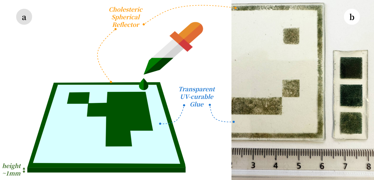
Core Structure and Material: The primary material used to make iMarkers is CSRs, microscopic droplets of Cholesteric Liquid Crystals (CLCs) that self-organize into a helical structure, making them highly effective at reflecting specific wavelengths of light, including IR, Ultraviolet (UV), or visible [5]. Thus, they can produce vivid, circularly polarized iridescent colors resulting from the selective reflection of light. As shown in Fig. 2, iMarkers combine CSRs for the marker patterns with transparent UV-curable glue to maintain the structure of the fiducial marker. An alternative fabrication method involves directly spraying CSR shells onto surfaces, a promising approach currently under investigation.
Coding and Recognition: iMarkers support various coding patterns for recognition and information retrieval. This paper focuses on ArUco-based [11] markers with variant dictionaries, but other standard fiducial marker libraries can also be adapted to the iMarker design.
Fabrication Efficiency: The cost and simplicity of fabrication significantly impact the widespread adoption of fiducial markers. While AirCode requires partitioning and InfraStructs depend on complex, layered assembly, iMarkers, as shown in Fig. 2, can be fabricated using conventional and cost-effective methods like dispensing or spray coating.
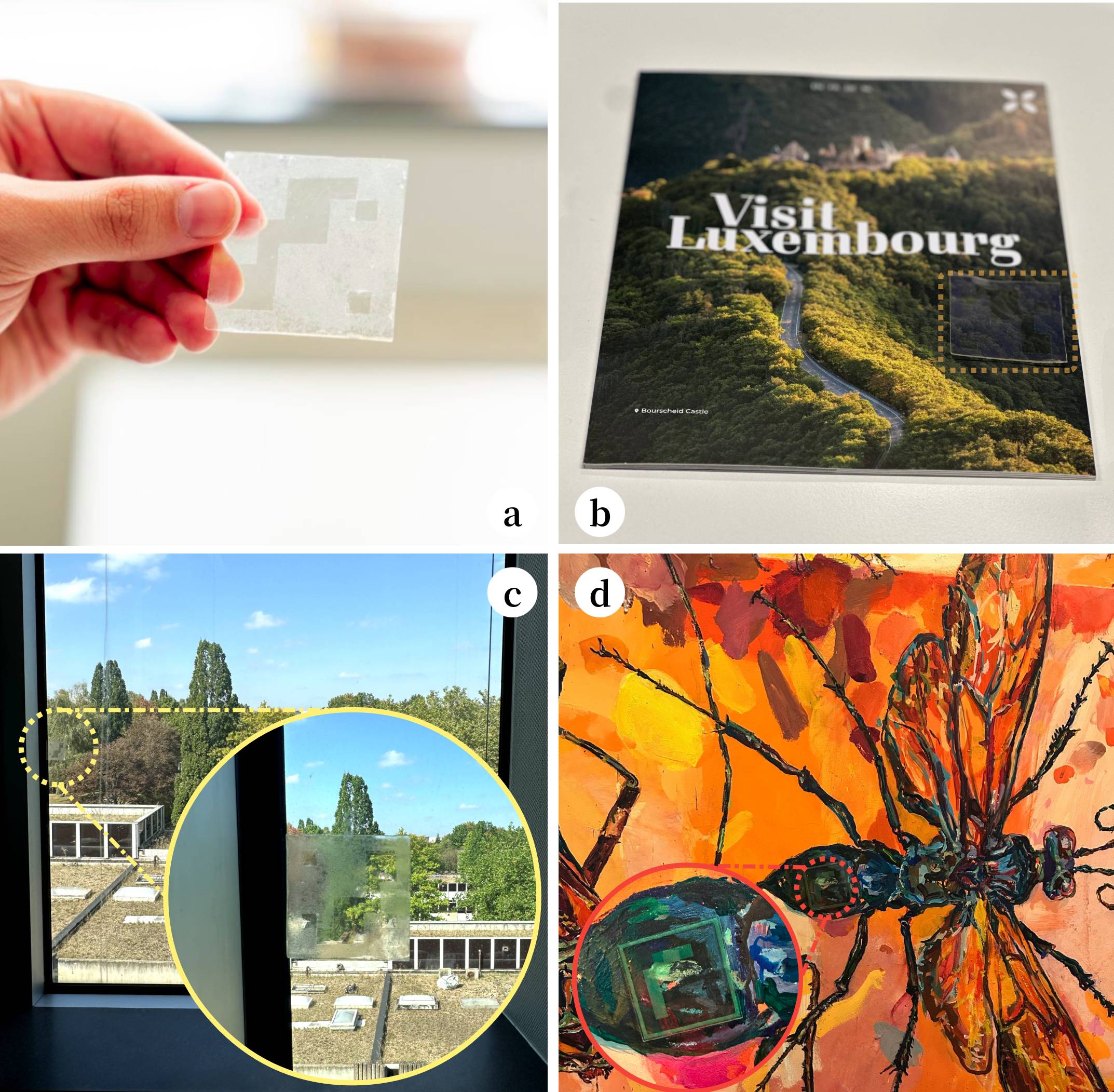
Production Versatility: In contrast with other solutions, iMarkers offer production flexibility, enabling fabrication and detection across the entire light spectrum. UV-range iMarkers remain entirely transparent and invisible to the naked eye, even when positioned on a transparent surface like glass. IR-range iMarkers are similarly discreet, though slight scattering or subtle color effects may reveal their presence (to some extent) under extreme lighting conditions. Even in the visible range, iMarkers can be designed to blend with patterned backgrounds or camouflage against similarly colored surfaces, ensuring minimal visual intrusion. Fig. 3 depicts actual examples of iMarkers made from different CSR shells.
Sensor Affordability: Detection requirements differ among unobtrusive marker solutions: AirCode relies on a large projector and camera setup, InfraStructs require costly Terahertz scanners, and InfraredTags depend on specialized imaging modules with microprocessors. In contrast, iMarkers can be detected using affordable sensors equipped with optical components. The camera for detecting iMarkers must be compatible with the polarization and wavelength characteristics of the CSRs employed in its fabrication. Details on the various sensor-software detector pairs optimized for iMarkers are provided in Section 4.
4 Sensor Design and Detection Strategies
Considering the unique structure of iMarkers, their perception sensors and detection algorithms differ from those used in conventional systems. In this context, the vision sensor is precisely engineered to maximize the iMarker distinction, facilitating efficient detection by the supplemental software. Sequences of binary images with distinct iMarker borders and patterns are fed to standard fiducial marker detector libraries for information decoding. Hence, three primary solutions are proposed for iMarker detection, including “dual-vision,” “static single-vision,” and “dynamic single-vision,” which are further described in the following:
4.1 Dual-vision Solution
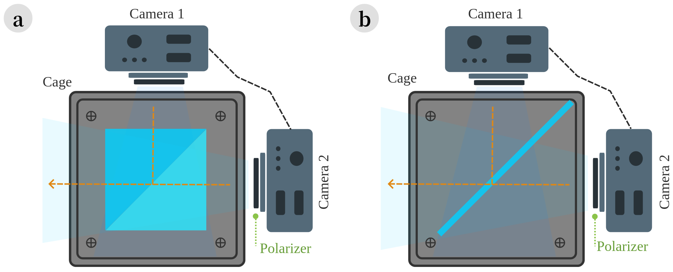
Sensor Design. The first sensor is a homogeneous perception system containing two perpendicularly positioned synchronized cameras, each facing a different surface of an optical beamsplitter. As shown in Fig. 4, the sensor can be assembled in two variants: one using a cube and the other employing a plate beamsplitter. The beamsplitter divides the incoming light equally (i.e., ) into two parts, including the transmitted (that passes through) and the reflected light. Thus, by mounting the cameras and beamsplitter within a cage setup, one camera captures the scene using the transmitted light, while the other captures it using the reflected light, resulting in two perspectives with minimal variation. Attaching identical circular polarizers to each camera’s lens effectively blocks light with the opposite circular polarization, ensuring only the desired handedness is detected.
Due to the inversion of circular polarization upon reflection in the beamsplitter, the camera capturing the reflected light detects the “opposite” circular polarization compared to the camera capturing the transmitted light. Accordingly, the sensor simultaneously captures the same scene with two cameras, ensuring that the CSR regions of iMarkers in the sensor’s Field of View (FoV) appear blocked in one camera while remaining visible in the other (due to the opposing circular polarization of the CSR reflections).
The cameras in this setup must be synchronized to capture the same scene simultaneously. Simplistically, frame captured by camera at time should depict the same scene as frame of camera . Additionally, as the cameras’ frame rate and shutter speed are vital factors for high-speed robotic applications (e.g., drone navigation), integrating global shutter cameras in this sensor is highly recommended. The calibration procedure for the setup involves capturing a standard calibration pattern (e.g., a chessboard) by each camera individually and with the entire sensor system. The camera’s intrinsic (e.g., focal length and distortion coefficients) and extrinsic parameters are required for iMarker pose estimation.
Detection Algorithm. Since the non-CSR regions of the scene lack circular polarization and appear identical in both cameras, it enables the use of simple computer vision techniques (e.g., image subtraction) to detect iMarkers with high contrast, as detailed in [5] and shown below. As shown in Algorithm 1, the iMarker detection procedure requires “spatial subtraction” of the synchronized frames captured by each camera. Having and as the synchronized frame sets captured by calibrated cameras and , each frame finds its corresponding synchronized frame . The next stage is aligning based on using the alignment parameters (captured during calibration), where is the homography matrix generated through matching Oriented FAST and Rotated BRIEF (ORB) features. Subtracting the “aligned” from the “original” frame results in the final binary image containing the input images’ dissimilar parts. Since the CSR region of iMarkers is visible in one frame and blocked in the other, only the patterns created by CSRs are expected to remain in . Then, a thresholding process with a value of , followed by post-processing, is applied to to generate a binary frame that enhances the iMarker patterns’ visibility. The final processed frame contains the potential iMarkers , in which is the set of iMarkers found in and at time .
4.2 Static Single-vision Setup
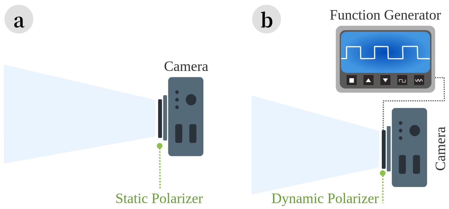
Sensor Design. The second approach offers a solution for iMarker detection using a single camera equipped with a circular polarizer attached to its lens (Fig. 5-a). The static polarizer attached to the camera’s lens is selected to block the circular polarization reflected by the CSRs forming the iMarker pattern. For instance, a left-handed circular polarizer will block iMarker regions with CSRs reflecting right-handed polarization, and vice versa. Thus, a visible-range iMarker with CSRs reflecting green right-hand polarized light on a same-color background, indistinguishable from the human eye or standard cameras, becomes detectable as the sensor’s left-handed polarizer blocks the CSR regions, revealing the camouflaged iMarker patterns. This design is well-suited for detecting visible-range iMarkers camouflaged within their environment, while it can also be used for IR/UV-range iMarkers using proper cameras.
Detection Algorithm. Unlike the dual-vision solution, the algorithm for the static single-vision setup does not eliminate the background. However, it simplifies constructing and integrating an iMarker detection sensor by shifting more computation to the detector methodology, achieving a practical balance between complexity and performance. For the visible-range camouflaged iMarkers, the procedure is shown in Algorithm 2. Accordingly, detecting iMarkers in a frame involves converting from RGB to HSV color space to isolate the color range corresponding to the marker. The resulting mask frame highlights the target color range as black pixels, with all other areas appearing as white. With the assistance of the polarizer, the mask frame highlights the blocked CSR regions of an iMarker with color (e.g., green) positioned against a background of the same color. Subsequent stages of the algorithm apply post-processing to eliminate noise, followed by detecting marker patterns within .
Detecting UV/IR-range iMarkers follows the same stages as the visible-range detection, provided that a UV/IR-range camera is used. However, “color masking” is unnecessary since the input is grayscale, and “range thresholding” is applied to identify the intensity variations in CSR regions, highlighting the iMarker patterns. Algorithm 3 can be employed for UV/IR-range iMarker detection scenarios.
4.3 Dynamic Single-vision Setup
Sensor Design. Another single-camera configuration (Fig. 5-b) utilizes a switchable (dynamic) circular polarizer alternating between left- and right-handed polarization, which will be described in detail in a forthcoming paper. In brief, it comprises a fixed circular polarizer paired with a nematic liquid crystal film that functions as a -plate in its relaxed (OFF) state and loses its optical functionality when an electric field is applied (ON). A -plate converts one circular polarization to its opposite; therefore, by switching the liquid crystal film between its ON and OFF states (controlled by a function generator synchronized with the camera’s frame rate), the camera sequentially captures frames with right- and left-handed polarization, separated in time. In an ideal setup, camera frame captures the scene with a particular polarization (left- or right-handed), and frame captures it with the opposite polarization. Thus, the function generator should send signal to trigger the liquid crystal film at time based on Equation 1:
| (1) |
The liquid crystal cell’s OFF-to-ON switching time is negligible and can be ignored; however, the ON-to-OFF relaxation is slower. Thus, the intermediate frames with undefined polarization for high frame rates may need to be discarded for the iMarker detection procedure. Once optimized for the liquid crystal cell, it ensures that CSR-coated regions in the iMarkers are blocked in one processed frame and visible in the next.
Detection Algorithm. Inspired by the “spatial” frame processing in the dual-vision setup, this approach employs a frame-level algorithm that uses “temporal” subtraction to detect the iMarker patterns. Assuming the liquid crystal film operates sufficiently fast relative to the video frame rate to produce sequential frames with alternating polarization states (as illustrated in Equation 1), the consecutive (temporal) frame subtraction algorithm to detect iMarkers using a switchable polarizer is shown in Algorithm 4. In this process, each frame and its subsequent frame , captured with alternating polarization states, are subtracted to produce a grayscale image , which can then be enhanced through post-processing to facilitate iMarker detection. Additionally, the current frame is stored for subtraction from its succeeding frame in the next iteration. As with the previous approaches, the final stage involves detecting fiducial markers within the processed frame .
5 Benchmarking and Evaluation
This section explores the potential and applicability of iMarkers from various aspects of real-world scenarios.
5.1 Operational Implementation
Considering the iMarker detection strategies outlined in Section 4, real-world sensor employment and algorithm implementation are the focus of this subsection to form the basis for subsequent evaluations.
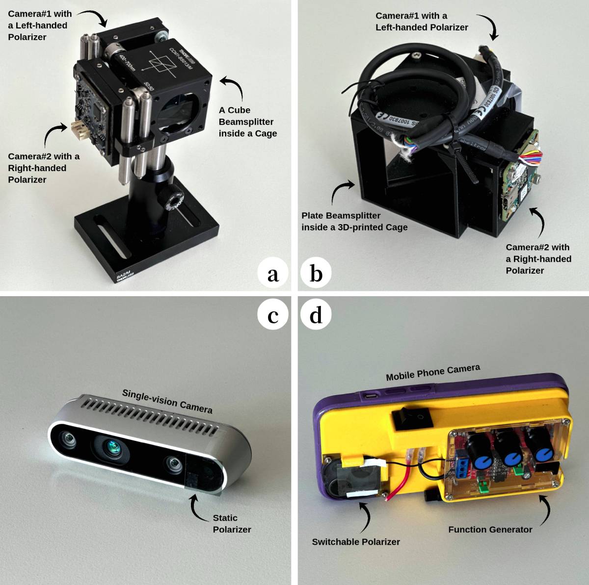
Sensor. Fig. 6 depicts the different sensor configurations developed for iMarker detection. The dual-vision setup shown in Fig. 6-a comprises two ELP 8MP HD camera modules with FoV facing a Thorlabs polarizing cube beamsplitter with a 50:50 split ratio, all mounted in a compact cage assembly. The other dual-vision setup in Fig. 6-b contains two synchronized U3-3271LE iDS cameras aligned with a Thorlabs polarizing plate beamsplitter housed within a custom-designed 3D-printed cage. The static single-vision setup shown in Fig. 6-c is an Intel® RealSense™ D435 camera equipped with a left-handed circular polarizer affixed to its RGB lens, effectively blocking the right-handed CSR-coated areas of camouflaged iMarkers. Finally, the dynamic single-vision sensor setup in Fig. 6-d incorporates a switchable polarizer controlled by a function generator mounted on an iPhone 13 case and aligned with its camera. While this prototype relies on manual polarizer switching, we are investigating a real-time version where the detection software dynamically synchronizes the camera and function generator to adjust polarization (left- or right-handed).
Software. Based on the detection algorithms outlined in Section 4, two software variants have been developed to support iMarker detection for general and robotics researchers. These variants include a “standalone Python application” with a Graphical User Interface (GUI) for visualization and configuration and a “ Robot Operating System (ROS)-based version” designed for robotics tasks. Both variants will be publicly available soon at https://snt-arg.github.io/iMarkers/.
5.2 Qualitative Evaluation
Given the complexity of measuring aesthetic perception, this section aims to visually assess iMarkers and showcase their detection performance. To achieve this, various iMarkers were strategically placed in rigid real-world locations and captured using different hardware sensors, highlighting their seamless integration into diverse settings. Fig. 7 depicts several qualitative results, showing the versatility of iMarkers across different spectral ranges and detection setups.
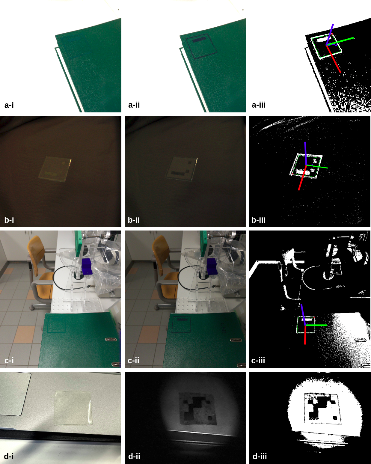
Accordingly, row “a” of Fig. 7 presents a visible-range green iMarker on a same-color background. In this scenario, Fig. 7-a-i shows its appearance to the naked eye, confirming its transparency and unobtrusiveness. Fig. 7-a-ii depicts its captured shot using the static single-vision setup, and Fig. 7-a-iii demonstrates the detection and pose estimation outcome using Algorithm 2. Row “b” focuses on the dual-vision setup output aiming at a visible-range iMarker on a patterned surface under low-light conditions. In this case, Figures 7-b-i and 7-b-ii capture images via left- and right-handed polarizers attached to the sensor cameras, respectively. The outcome is shown in Fig. 7-b-iii, where the iMarker is recognized using Algorithm 1. The performance of the dynamic single-vision setup is shown in the row “c,” where stores the scene in Fig. 7-c-i and captures Fig. 7-c-ii. The “temporal” subtraction output based on Algorithm 4 is illustrated in Fig. 7-c-iii. Finally, the UV-range iMarker placed on a laptop guarantees exceptional invisibility to the naked eye (Fig. 7-d-i). However, the inner patterns become visible using a near-UV illumination when captured by a UV-range camera (Fig. 7-d-ii). Applying the methodology introduced in Algorithm 3, as shown in Fig. 7-d-iii, will facilitate the recognition process.
5.3 Detection Range Evaluation
A comparative experiment was conducted using printed markers and iMarkers, both formatted as ArUco markers [11], to evaluate the effectiveness of iMarkers w.r.t. traditional markers and analyze potential variations in detection performance. The markers were affixed to a vertical surface, and detection tests were performed from various distances and viewing angles. The objective was to identify the maximum distance at different angles where the markers remained detectable using the ArUco detection algorithm. The experiments utilized a static single-vision setup (shown in Fig. 6) for iMarker detection, while the same sensor without a polarizer was used for printed marker detection.
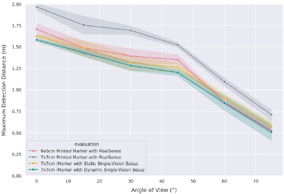
According to the experimental results depicted in Fig. 8, the static and dynamic single-vision setups show negligible differences in maximum detection ranges, differing only by an average of . However, the disparity in detection ranges between printed markers and iMarkers is more pronounced, ranging from to . This variation is minor when the viewing angle approaches and more significant for more direct angles (). Considering the purpose of introducing iMarkers, and given that printed markers are specifically designed as high-contrast landmarks for optimal visibility, such results are expected. iMarkers offer a distinct advantage with their unobtrusive design, allowing unnoticeable integration into environments without compromising visual aesthetics. This trade-off highlights the practicality of iMarkers for applications where invisibility to the human eye is crucial while maintaining reliable detection by robotic systems.
5.4 Recognition Speed
| iMarker Variant | |||||
| UV | Visible-range | ||||
| Software Module | SV Static | SV Static | SV Dynamic | DV (cube BS) | DV (plate BS) |
| GUI-related | |||||
| Acquisition | |||||
| Preprocessing | |||||
| Processing | |||||
| Post-processing | |||||
| Recognition | |||||
| Sum | |||||
| ∗PS. SV: Single-Vision, DV: Dual-Vision, UV: Ultraviolet, BS: Beamsplitter | |||||
Considering the necessity of fast recognition speeds in demonstrating the practicality of fiducial markers for real-time applications, this subsection provides a detailed profiling analysis of iMarker detection and recognition. Table 2 summarizes cumulative processing times for iMarker data decoding using various sensor configurations discussed in subsection 5.1. Evaluations were conducted using the implemented “standalone Python application” introduced in the mentioned subsection. To obtain the measurements, iMarkers were placed approximately from the lens, directly facing the sensor under normal illumination conditions. For the UV-range iMarker, a near-UV light source was also employed.
According to the table, the overall iMarker recognition process, from image acquisition and user interface loading to marker recognition, is completed within milliseconds. To compare, some methods discussed in Table 1 require several seconds for detection, highlighting the efficiency of the iMarker system. In dual-vision setups, “frame acquisition” and “processing” account for the subsequent significant portions of the processing time due to the need to receive synchronized frames from two cameras and perform image alignment for further processing, respectively. However, the “post processing” and “marker recognition” procedures are executed exceptionally quickly, owing to the binary nature of the image feeds.
6 Discussion
6.1 Comparative Insights
Fig. 9 depicts relative performance scores of different iMarker fabrication variants and the designed sensor configurations for their detection. Accordingly, UV-range markers exhibit the highest level of invisibility, detection equipment cost (sensor, flashlight, etc.), and sensitivity to ambient light. This variant of iMarkers is ideal for applications demanding a high degree of constraint and security. In addition, the user should orient the near-UV light source toward the iMarker, which might be challenging due to the marker’s invisible nature. Visible-range camouflaged iMarkers achieve ideal readability while remaining minimally visible to the human eye upon close inspection. The advantages of this variant are a more straightforward sensor design and increased detectability without additional illumination. Finally, despite maintaining appropriate unobtrusiveness, the IR-range version shows more vulnerability to environmental factors due to potential occlusion by materials that absorb or block infrared light. IR-range iMarkers also demand a an IR-sensitive sensor and illuminator for detection.
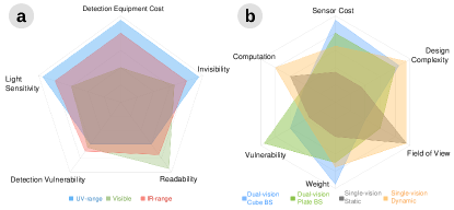
Regarding the sensors, dual-vision setups are vulnerable to mechanical component misalignment (i.e., camera and beamsplitter), resulting in noisy frame subtraction and reduced marker detection accuracy. Unlike the dual-vision cube beamsplitter setup with standard optical cage cubes, the plate beamsplitter variant is more susceptible to misalignment due to its custom-designed mount. Hence, vibration and thermal expansion can cause the screws to become loosened or the cameras to shift out of their precise alignment, reducing the reliability of the captured data. Dual-vision setups also restrict the cameras’ FoV by excluding regions outside the beamsplitter coverage, regardless of its size or variation. However, they demand the least computational cost for iMarker detection by filtering out non-CSR regions and processing only the output binary image. Static single-vision setup is the most uncomplicated sensor design, imposing higher algorithmic overhead for iMarker detection. This solution may encounter challenges in scenarios with varying illumination, necessitating adjustments in “masking” and “threshold” parameters. Moreover, single-vision setups are more feasible for minimizing payloads, such as in drones, as dual-vision configurations are heavier. The combined weight of dual-vision setup components typically ranges from 150 to 350 grams, with the plate beamsplitter potentially reducing the overall sensor weight.
6.2 Applicability
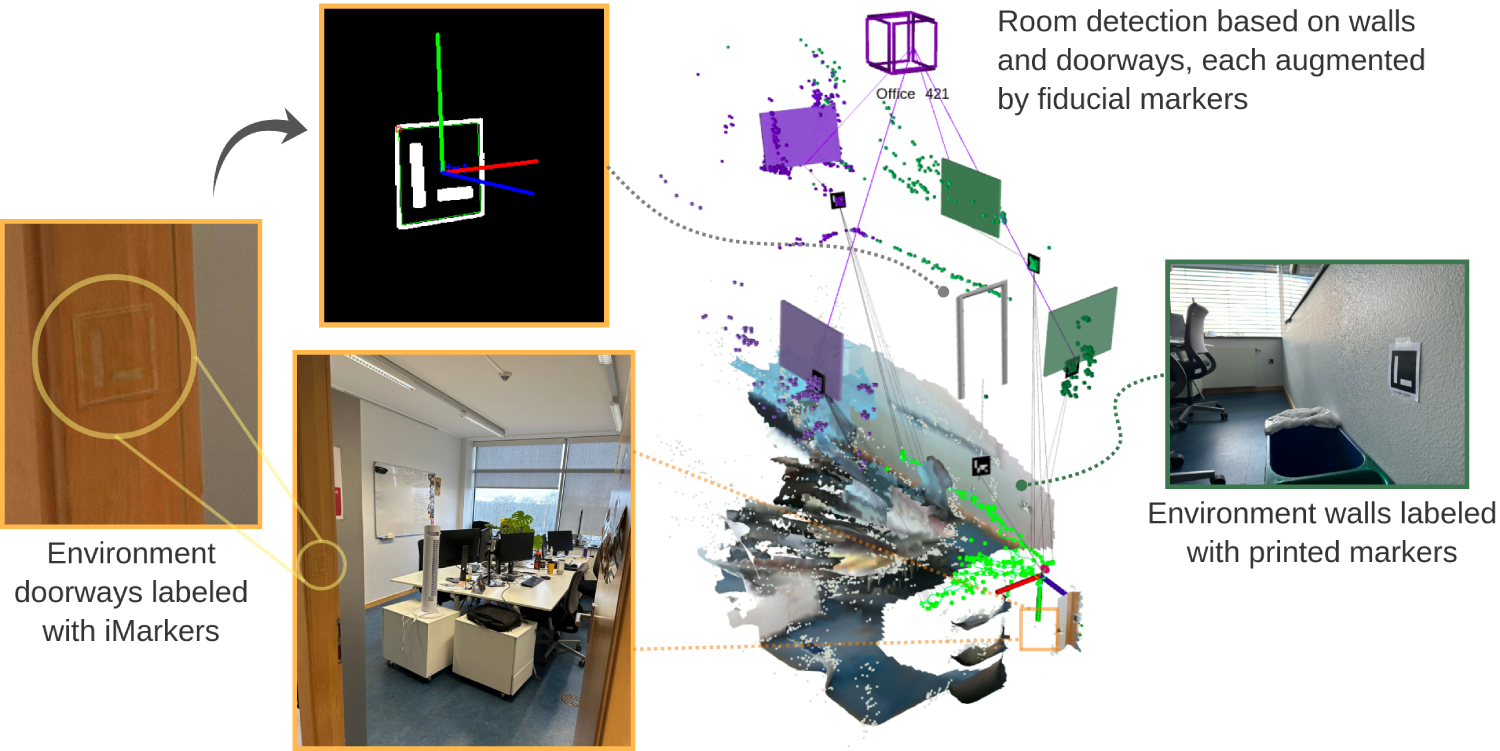
Considering the unique characteristics of iMarkers, they serve as potential alternatives in scenarios reliant on printed markers. By safely replacing printed markers, iMarkers can preserve unobtrusiveness and aesthetic integrity while delivering full functionality for robotics and AR systems. Their obscure nature makes them appropriate for surroundings with unwanted visual clutter, such as museums and offices. Fig. 10 depicts the real-world benchmarking of iMarkers in visual Simultaneous Localization and Mapping (SLAM), showcasing the use of a visible-range iMarker to facilitate indoor map reconstruction enriched with semantic information [20]. iMarkers can also be suitable for autonomous robots functioning in retail stores and smart warehousing, where numerous markers are needed to augment objects. Another potential use case includes object grasping in cluttered environments, where iMarkers can supply accurate localization cues to enhance robotic manipulation accuracy. iMarkers can also be strategically employed to seamlessly augment difficult-to-detect objects, like transparent surfaces (e.g., windows and glass block walls), where the transparency poses considerable challenges to computer vision and robot perception systems. Likewise, reflective surfaces, such as mirrors or chrome/metallic objects, often cause distortions or reflections, confusing perception algorithms and negatively impacting object recognition or localization accuracy. In these scenarios, iMarkers can augment such objects by providing reliable information while preserving visual appeal. This allows robots and AR devices to effectively “see” and interact with visually challenging entities, ensuring reliable operation and versatility.
6.3 Limitations
Considering the ongoing nature of the research project and the technical fabricating process of CSR shells, the experiments are constrained by the limited variety and quantity of available shells, restricting the ability to produce and evaluate many iMarkers. Additionally, long-term exposure to environmental factors may affect marker visibility, as markers tend to develop a yellowish tint over time.
7 Conclusions
This paper introduced a novel generation of fiducial markers, termed iMarkers, designed explicitly for real-world robotics applications. iMarkers are designed to be visually indistinguishable from the human eye, ensuring minimal environmental disruption while remaining fully detectable and recognizable by robots equipped with specialized sensors and advanced detection algorithms. The paper also presents various sensor designs and implemented algorithms for detecting iMarkers placed in the environment and exploiting them for different use cases. Experimental results demonstrate the practicality and potential of these markers as versatile landmarks for data embedding in various real-world scenarios.
Future works include optimizing the iMarker fabrication process to ensure scalable production and enhancing sensor designs and algorithm implementations to guarantee robustness across various environmental conditions. Another plan is to conduct visual SLAM experimentation in real-world environments augmented with iMarkers.
Acknowledgments
The authors would like to thank Marco Giberna for his insightful discussions and contributions to the experiments conducted in this work.
References
- [1] M. Kalaitzakis, B. Cain, S. Carroll, A. Ambrosi, C. Whitehead, and N. Vitzilaios, “Fiducial markers for pose estimation: Overview, applications and experimental comparison of the artag, apriltag, aruco and stag markers,” Journal of Intelligent & Robotic Systems, vol. 101, pp. 1–26, 2021.
- [2] G. M. Costa, M. R. Petry, J. G. Martins, and A. P. Moreira, “Assessment of multiple fiducial marker trackers on hololens 2,” IEEE Access, 2024.
- [3] N. Ayala, D. Mardanbegi, A. Zafar, E. Niechwiej-Szwedo, S. Cao, S. Kearns, E. Irving, and A. T. Duchowski, “Does fiducial marker visibility impact task performance and information processing in novice and low-time pilots?” Computers & Graphics, vol. 119, p. 103889, 2024.
- [4] M. Schwartz, Y. Geng, H. Agha, R. Kizhakidathazhath, D. Liu, G. Lenzini, and J. P. Lagerwall, “Linking physical objects to their digital twins via fiducial markers designed for invisibility to humans,” Multifunctional Materials, vol. 4, no. 2, p. 022002, 2021.
- [5] H. Agha, Y. Geng, X. Ma, D. I. Avşar, R. Kizhakidathazhath, Y.-S. Zhang, A. Tourani, H. Bavle, J.-L. Sanchez-Lopez, H. Voos et al., “Unclonable human-invisible machine vision markers leveraging the omnidirectional chiral bragg diffraction of cholesteric spherical reflectors,” Light: Science & Applications, vol. 11, no. 1, pp. 1–19, 2022.
- [6] L. Naimark and E. Foxlin, “Circular data matrix fiducial system and robust image processing for a wearable vision-inertial self-tracker,” in Proceedings. International Symposium on Mixed and Augmented Reality, 2002, pp. 27–36.
- [7] P. Lightbody, T. Krajník, and M. Hanheide, “A versatile high-performance visual fiducial marker detection system with scalable identity encoding,” in Proceedings of the Symposium on Applied Computing, 2017, pp. 276–282.
- [8] F. Bergamasco, A. Albarelli, E. Rodola, and A. Torsello, “Rune-tag: A high accuracy fiducial marker with strong occlusion resilience,” in 2011 IEEE Computer Society Conference on Computer Vision and Pattern Recognition (CVPR’11). IEEE, 2011, pp. 113–120.
- [9] H. Kato and M. Billinghurst, “Marker tracking and hmd calibration for a video-based augmented reality conferencing system,” in Proceedings 2nd IEEE and ACM International Workshop on Augmented Reality (IWAR’99). IEEE, 1999, pp. 85–94.
- [10] E. Olson, “Apriltag: A robust and flexible visual fiducial system,” in 2011 IEEE International Conference on Robotics and Automation. IEEE, 2011, pp. 3400–3407.
- [11] S. Garrido-Jurado, R. Muñoz-Salinas, F. J. Madrid-Cuevas, and M. J. Marín-Jiménez, “Automatic generation and detection of highly reliable fiducial markers under occlusion,” Pattern Recognition, vol. 47, no. 6, pp. 2280–2292, 2014.
- [12] R. M. Claro, D. B. Silva, and A. M. Pinto, “Artuga: A novel multimodal fiducial marker for aerial robotics,” Robotics and Autonomous Systems, vol. 163, p. 104398, 2023.
- [13] C. Getschmann and F. Echtler, “Seedmarkers: Embeddable markers for physical objects,” in Proceedings of the Fifteenth International Conference on Tangible, Embedded, and Embodied Interaction, 2021, pp. 1–11.
- [14] Y. Wang, Y. Ji, D. Liu, Y. Tamura, H. Tsuchiya, A. Yamashita, and H. Asama, “Acmarker: Acoustic camera-based fiducial marker system in underwater environment,” IEEE Robotics and Automation Letters, vol. 5, no. 4, pp. 5018–5025, 2020.
- [15] H. Uchiyama and Y. Oyamada, “Transparent random dot markers,” in 2018 24th International Conference on Pattern Recognition (ICPR). IEEE, 2018, pp. 254–259.
- [16] M. D. Dogan, A. Taka, M. Lu, Y. Zhu, A. Kumar, A. Gupta, and S. Mueller, “Infraredtags: Embedding invisible ar markers and barcodes using low-cost, infrared-based 3d printing and imaging tools,” in Proceedings of the 2022 CHI Conference on Human Factors in Computing Systems, 2022, pp. 1–12.
- [17] M. D. Dogan, R. Garcia-Martin, P. W. Haertel, J. J. O’Keefe, A. Taka, A. Aurora, R. Sanchez-Reillo, and S. Mueller, “Brightmarker: 3d printed fluorescent markers for object tracking,” in Proceedings of the 36th Annual ACM Symposium on User Interface Software and Technology, 2023, pp. 1–13.
- [18] D. Li, A. S. Nair, S. K. Nayar, and C. Zheng, “Aircode: Unobtrusive physical tags for digital fabrication,” in Proceedings of the 30th annual ACM symposium on user interface software and technology, 2017, pp. 449–460.
- [19] K. D. Willis and A. D. Wilson, “Infrastructs: fabricating information inside physical objects for imaging in the terahertz region,” ACM Transactions on Graphics (TOG), vol. 32, no. 4, pp. 1–10, 2013.
- [20] A. Tourani, H. Bavle, D. I. Avşar, J. L. Sanchez-Lopez, R. Munoz-Salinas, and H. Voos, “Vision-based situational graphs exploiting fiducial markers for the integration of semantic entities,” Robotics, vol. 13, no. 7, p. 106, 2024.