Modern Base Station Architecture: Enabling Passive Beamforming with Beyond Diagonal RISs
Abstract
Beamforming plays a crucial role in millimeter wave (mmWave) communication systems to mitigate the severe attenuation inherent to this spectrum. However, the use of large active antenna arrays in conventional architectures often results in high implementation costs and excessive power consumption, limiting their practicality. As an alternative, deploying large arrays at transceivers using passive devices, such as reconfigurable intelligent surfaces (RISs), offers a more cost-effective and energy-efficient solution. In this paper, we investigate a promising base station (BS) architecture that integrates a beyond diagonal RIS (BD-RIS) within the BS to enable passive beamforming. By utilizing Takagi’s decomposition and leveraging the effective beamforming vector, the RIS profile can be designed to enable passive beamforming directed toward the target. Through the beamforming analysis, we reveal that BD-RIS provides robust beamforming performance across various system configurations, whereas the traditional diagonal RIS (D-RIS) exhibits instability with increasing RIS size and decreasing BS-RIS separation—two critical factors in optimizing RIS-assisted systems. Comprehensive computer simulation results across various aspects validate the superiority of the proposed BS-integrated BD-RIS over conventional D-RIS architectures, showcasing performance comparable to active analog beamforming antenna arrays.
Index Terms:
Beyond diagonal RIS, millimeter wave, bit error rate, achievable rate, passive beamforming.I Introduction
The rapid evolution of wireless communication systems is driven by the ever-increasing demand for enhanced network access and capacity. Given the growing need for frequency spectrum to support emerging applications, utilizing higher frequency bands, such as the millimeter-wave (mmWave) spectrum, continues to be a vital enabler for advanced communication systems, including sixth-generation (6G) networks [1, 2, 3]. The abundant bandwidth available in the mmWave spectrum enables high data rate and low latency communication, aligning well with 6G requirements. Additionally, the short wavelength of mmWave signals allows the integration of a large number of antennas, facilitating the formation of highly directional beams. While the primary goal of these beams is to overcome the significant path loss inherent in mmWave environments, their directional nature can be effectively leveraged in multi-user systems to minimize inter-user interference and facilitate massive connectivity in 6G networks [4, 5].
Despite the advantages of mmWave systems, the required equipment for their implementation is both costly and power-intensive [6], which is misaligned with the stringent energy efficiency requirements of 6G networks. To tackle this challenge, hybrid beamforming is proposed as an alternative to fully digital beamforming, reducing the number of radio frequency (RF) chains at transceivers by employing a network of analog phase shifters following baseband precoding. However, the analog network still relies on a large number of high-precision active phase shifters, which can pose challenges to the practical implementation of large antenna arrays [6].
Reconfigurable intelligent surfaces (RISs) have recently emerged as a promising solution to enhance wireless communication systems by dynamically controlling the propagation environment [7, 8]. However, beyond their conventional role as auxiliary reflectors, an intriguing question arises: Can RISs serve as primary beamformers at the base station (BS) or user equipment (UE)? Such an approach would leverage the passive and cost-effective nature of RISs, significantly reducing hardware complexity and power consumption compared to traditional active analog beamforming. This consideration opens new avenues for exploring BS/UE-integrated RISs, where RISs are seamlessly embedded into transceiver designs to enable passive beamforming.
I-A Related Works
Hybrid beamforming has gained significant attention as a cost-effective alternative to fully digital beamforming in mmWave systems. In this context, [9] introduces an angular-based hybrid precoding and combining approach for mmWave massive MIMO systems, focusing on minimizing channel state information (CSI) overhead. [4] evaluates three-dimensional (3D) antenna array structures for hybrid precoder design in multi-user mmWave massive MIMO. The authors in [5] proposes a two-stage angular-based hybrid precoding method, grouping users by angular similarity. To further reduce system costs, [6] presents a fixed phase shifter design that reduces the number of phase shifters in hybrid precoding architectures, offering a cost-efficient solution. Although the adoption of analog phase shifters significantly reduces the number of RF chains, implementing massive MIMO still requires a large number of phase shifters, which can lead to increased cost, complexity, and power consumption [6].
Programmable metasurfaces have gained attention for their passive nature and ability to enable low-cost arrays that direct incident electromagnetic (EM) waves. Explored types include passive RIS [7], active RIS [10], simultaneously transmitting and receiving (STAR) RIS [11], stacked intelligent metasurface (SIM), and beyond diagonal (BD) RIS [12]. Some studies propose RISs as primary beamformers at the BS or UE to simplify massive MIMO deployment [13, 8]. Furthermore, integrating RIS directly within transceivers mitigates the multiplicative path loss challenges typically associated with conventional RIS-assisted systems [8].
User-side RIS integration has been specifically explored in [14, 15] as a means to realize cost- and energy-efficient large-scale arrays. The authors in [16] propose integrating an RIS within the radome of a BS as an auxiliary passive array, enabling real-time reconfiguration to enhance system performance cost-effectively. In [17], a hybrid beamforming approach is proposed, targeting sidelobe suppression and mainlobe optimization through a least squares-based cost function applied to BS digital beamforming and intelligent transmissive surface phase configurations. A notable advancement in this domain is SIM, which seamlessly integrates RIS technology within the BS or UE to enable the passive implementation of advanced MIMO functionalities. By employing multiple layers of low-cost meta-atoms, SIM facilitates the deployment of large arrays at transceivers using passive components [13, 18, 19, 20, 21].
BD-RIS represents an advanced evolution of RIS technology, offering enhanced flexibility by enabling the manipulation of both the phase and amplitude of impinging signals without introducing amplification or attenuation [12, 22, 23]. Unlike traditional diagonal RIS (D-RIS), a BD-RIS incorporates inter-element connectivity, which allows for amplitude adjustment across RIS elements, significantly enhancing its beamforming capabilities. This advanced functionality makes BD-RIS a compelling choice for integration at transceivers, where its ability to passively perform analog beamforming can replace conventional analog phase shifters, simplifying the transceiver design while maintaining high performance. As discussed in [24], BD-RIS outperforms D-RIS when the magnitudes of the individual elements of the BS-RIS and RIS-UE channels are linearly independent. This implies that rich-scattered channels, such as those modeled by Rayleigh fading, create favorable conditions for BD-RIS to surpass D-RIS. Moreover, increasing the number of UEs enriches the channel, further benefiting BD-RIS. However, as the channel becomes more scattered, the performance gap between BD-RIS and D-RIS narrows.
Initial efforts have been invested to evaluate the potential of BD-RIS. The work of [25] explores a reflective BD-RIS integrated within the BS, focusing on the sub-6 GHz spectrum. The study considers a multi-user system and shows that BD-RIS outperforms D-RIS by more effectively mitigating inter-user interference. [26] investigates an integrated sensing and communication (ISAC) system with a BD-RIS integrated into the BS. Although the study focuses on the mmWave band, it models the NLOS channel component using a Rayleigh distribution, which does not accurately capture the spatially sparse scattering nature of mmWave environments. Additionally, the adoption of a multi-user system further enriches the channel, thereby amplifying the performance advantage of the BD-RIS over the traditional D-RIS. The study in [27] examines a SIM structure implemented with BD-RIS and demonstrates that a single-layer SIM with BD-RIS outperforms any SIM based on D-RIS, highlighting the significant potential of BD-RIS in RIS-integrated systems. However, the RIS-UE channel is modeled as rich-scattered using a Rayleigh distribution, creating favorable conditions for BD-RIS to surpass the performance of conventional D-RIS. It has been demonstrated in [28] that integrating a linear BD-RIS at the BS significantly enhances beamforming gain compared to D-RIS, but it focuses solely on linear configurations and localization parameter estimation limiting the application scenario.
I-B Motivations and Contributions
Integrating BD-RIS within the BS seamlessly incorporates it as part of the BS, rendering it indistinguishable as a separate unit from the perspective of the UE. Consequently, a fundamental step in designing such a structure involves evaluating system performance under varying BS design parameters, such as array size and BS-RIS separation. In this context, the BS-RIS channel assumes a pivotal role in the design process, as it is directly influenced by these parameters and remains entirely under the service provider’s control. While initial studies [25], [26], [27] have explored the concept of BS-integrated BD-RIS, they fall short of analyzing the impact of these design parameters on the proposed architecture. Notably, the primary advantage of BD-RIS over D-RIS lies in its ability to adjust the amplitude of impinging signals [12]. Given the close proximity of RIS to the active antenna a the BS, the amplitude variations of signals emitted by the active antenna across different RIS elements become significant. Thus, it is reasonable to anticipate that BD-RIS would outperform D-RIS without factoring in the RIS-UE channel. Furthermore, employing a Rayleigh channel model for the RIS-UE link or extending the analysis to multi-user scenarios, as partially considered in [25], [26], [27], introduces additional amplitude variations across the RIS elements, further amplifying the performance gains of BD-RIS over D-RIS.
The primary motivation for deploying large arrays and massive MIMO in high-frequency communication systems is forming narrow beams toward intended targets, effectively mitigating severe path loss and high attenuation. The influence of BS-integrated BD-RIS on beamforming gain, however, remains unexplored in the aforementioned studies. Moreover, the mmWave communication environment is characterized by spatially sparse scattering, making the assumption of a rich-scattering Rayleigh channel model unrealistic and disconnected from practical scenarios. With this in mind, the main contributions of this paper are summarized as follows:
-
•
BS-Enabled Passive Beamforming: We investigate a BS-integrated BD-RIS system model that facilitates passive beamforming at the BS by emulating a multiple-input single-output (MISO) configuration through a single-input single-output (SISO)-assisted BD-RIS. Using the widely-adopted geometric cluster-based channel model, which represents the spatially sparse scattered nature of mmWave environments, we demonstrate the BD-RIS’s ability to form narrow beams for efficient directional communications in a point-to-point (P2P) mmWave scenario. Notably, in contrary with [26, 27], our analysis reveals that a BD-RIS delivers high performance gains even in sparse scattering channels, proving that its effectiveness is not restricted to rich scattering environments. To configure the BD-RIS, we employ a simple algorithm based on Takagi’s decomposition, which effectively achieves beamforming gains comparable to those of active analog beamforming antenna arrays.
-
•
Geometric Grouping Strategy: We demonstrate that the internal geometry of the BS-integrated BD-RIS is pivotal in minimizing the circuit complexity of the proposed system. Achieving maximum beamforming gain does not require a fully-connected BD-RIS structure. Instead, by dividing the BD-RIS elements into groups that exhibit symmetry around the active antenna, it is possible to maintain the maximum beamforming gain, as the channel amplitude variations within each group are identical and match those of the entire BD-RIS. Notably, this approach is flexible and can be applied to any desired number of groups. Specifically, as long as symmetry around the active antenna is preserved within a group, that group can be further subdivided into smaller groups without compromising performance. To the best of our knowledge, group-connected BD-RIS strategies from the beamforming perspective within BS-integrated BD-RIS systems have not been previously explored.
-
•
Simulation Insights: We evaluate the beamforming gain of the proposed BS-integrated BD-RIS configured as a uniform planar array, benchmarking its performance against traditional D-RIS and active analog beamforming antenna arrays. By introducing a novel metric, termed channel amplitude variations, we pinpoint and address the beamforming limitations inherent in BS-integrated D-RIS architectures, a drawback that has not been thoroughly examined in previous works. Our findings reveal that the proposed BS-integrated BD-RIS achieves a beamforming gain and beam pattern comparable to the performance of active analog beamforming antenna arrays. In contrast, D-RIS exhibits limited beamforming capability and wider beam patterns. Besides, we conducted various simulations to evaluate the bit error rate (BER) and validate the results with the theoretical upper bound, along with a comprehensive achievable rate analysis across various parameters under various conditions.
The paper is organized as follows: Section II introduces the system, channel, and signal models. Section III outlines the BD-RIS architecture and its configuration algorithm for fully-connected and group-connected modes. Section IV highlights key differences between BD-RIS and conventional D-RIS, discussing the impact of design parameters on performance. Section V presents simulation results, comparing the proposed BS-integrated BD-RIS with benchmarks. Finally, Section VI concludes the paper.
II System, Channel, and Signal Model
In this section, we begin by presenting the system model, outlining the architecture of the proposed BS-integrated BD-RIS, the arrangement of its passive elements, and its role in enabling passive beamforming for efficient directional communication in the mmWave environment. Next, we detail the channel model, capturing the interaction between the active antenna and the BD-RIS, as well as the propagation characteristics of the wireless channel between the BD-RIS and the UE. We then describe the signal model, explaining the transmission of symbols, passive beamforming by the BD-RIS, and the formulation and detection of the received signal at the UE.
II-A System Model
Fig. 1 illustrates the proposed system model and the BS structure designed for deployment in a mmWave environment. Building upon the motivations discussed in Section I, we consider a P2P SISO system where the BS is equipped with a single active antenna and a passive BD-RIS integrated into the BS as depicted in Fig. 1(a). This configuration enables passive beamforming, effectively forming the beams to combat the severe path loss and attenuation characteristic of the mmWave spectrum [1, 29, 8]. Fig. 1(b) provides a 3D view of the BD-RIS side facing the active antenna, with the opposite side, which faces outward, having an identical structure. Each side of the BD-RIS is referred to as a sector, as illustrated in Fig. 1(c). For the proposed application, the BD-RIS operates exclusively in the transmissive mode (signals are sending to sector 2), with its reflective mode deactivated [22].
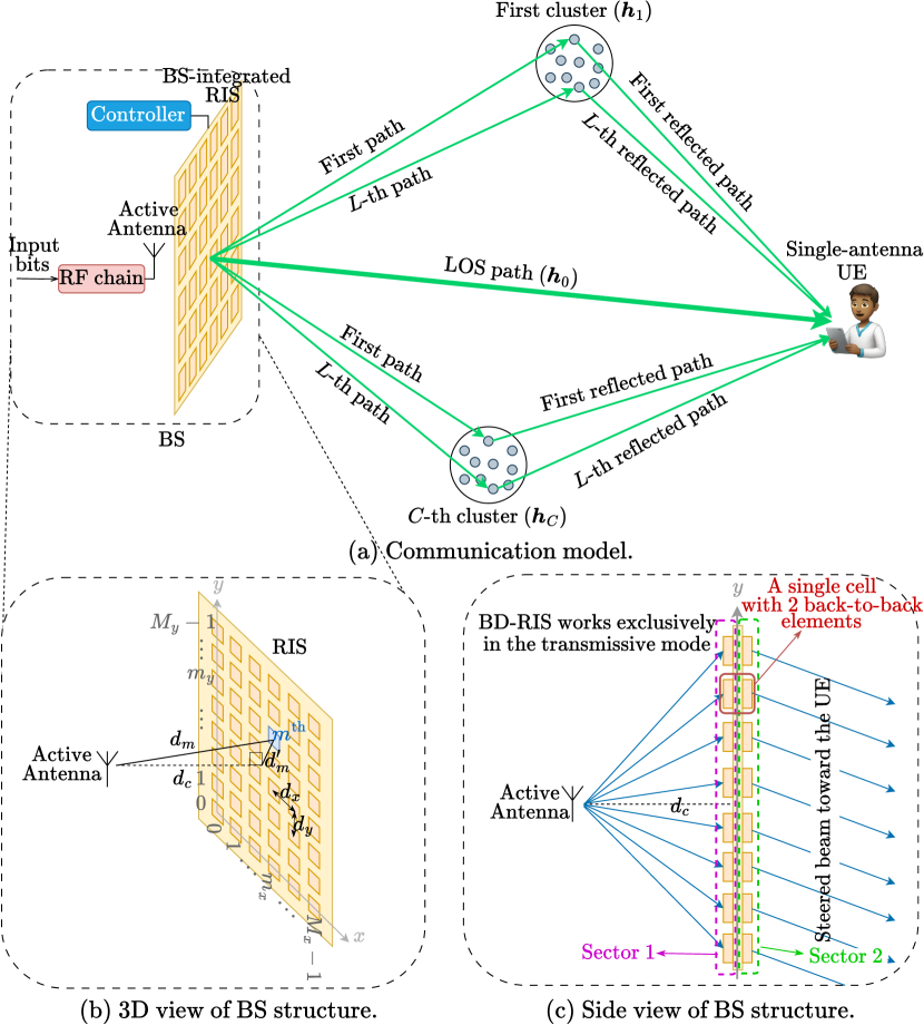
To facilitate exclusive transmissive operation, the passive elements on each side are organized into a uniform planar array with columns and rows. Each back-to-back pair of passive elements from the two sectors of the BD-RIS constitutes a single cell, enabling seamless coordination between the two sectors. This arrangement comprises a total of cells, allowing the integrated BD-RIS to effectively steer the EM wave radiated by the active antenna toward the UE. To maintain focus on the proposed system model, the details of the BD-RIS circuit are provided separately in Section III.
The spacing between adjacent columns along the -axis is , while the spacing between adjacent rows along the -axis is . The -th cell () is located at the intersection of the -th row () and -th column (), where the index is given by . The active antenna is positioned along an axis perpendicular to the RIS plane, passing through the geometric center of the RIS surface at a distance of , as shown in Fig. 1(b). Additionally, the distance between the active antenna and the -th cell is denoted as and defined as follows:
| (1) |
where represents the distance between the -th element and the center of the BD-RIS, defined as:
| (2) |
II-B Channel Model
In the proposed system, the channel between the active antenna and the BD-RIS plays a critical role in shaping the performance of passive beamforming. The integration of the BD-RIS within the BS introduces unique propagation characteristics, as the EM wave emitted by the active antenna interacts with each BD-RIS cell, arriving with distinct amplitudes and phases. To capture this interaction, the channel coefficient vector from the active antenna to the BD-RIS is derived using the Rayleigh-Sommerfeld diffraction theory for near-field propagation [30, 31, 32, 33, 21] as follows:
| (3) |
where represents the area of each passive element, and represents the wavelength of the carrier signal.
After traversing the BD-RIS, the signal propagates through the wireless channel between the BD-RIS and the UE. In the mmWave environment, such channels are characterized by significant propagation challenges, including penetration loss, severe path loss, and attenuation, which create a sparsely scattered propagation environment. To capture these conditions accurately, the widely recognized clustered geometric channel model is employed. This model accounts for the combined effect of a LOS path and multiple non-LOS (NLOS) clusters, as illustrated in Fig. 1(a). Specifically, the channel between the BD-RIS and UE, denoted as , is modeled as a superposition of these paths and is expressed as follows [1, 29, 34, 35]:
| (4) | ||||
where represents the number of NLOS clusters and denotes the number of NLOS paths in each cluster. The parameters , , and denote the complex path gain, azimuth angle of departure (AOD), and elevation AOD for the LOS path, respectively [1, 29]. For the -th path in the -th cluster, the corresponding parameters are , , and , representing the complex path gain, azimuth AOD, and elevation AOD, respectively [1, 29, 36]. Here, and are the mean azimuth and elevation AODs while denotes the angular spread in both the azimuth and elevation dimensions for the -th cluster [1, 29, 36]. The variances of the LOS and NLOS path gains are defined by , , where represents the path loss between the BD-RIS and UE, and denotes the distance between them. In addition, represents the array response (steering) vector at the BD-RIS transmit terminal, indicating that the corresponding path is directed toward the azimuth angle and elevation angle . The mathematical expression for is given as follows:
| (5) |
where represents the wave-number vector, which characterizes the direction of the corresponding path, and , , denotes the position vector of the -th cell, specifying its location on the BD-RIS. These vectors are mathematically expressed as:
| (6) |
| (7) |
Notably, in (4), the channel model is decomposed into the LOS sub-channel, represented by , and the summation of NLOS sub-channels, .
II-C Signal Model
This paper focuses on P2P communication, where a single stream of information bits is transmitted to a single-antenna UE. The transmitted symbol is chosen from an -ary constellation set of order and transmits to the BD-RIS through the transmission channel . As a result, the system’s spectral efficiency is defined as bits per channel use (bpcu). The BD-RIS applies a non-diagonal configuration scattering matrix to the incoming EM wave from the active antenna, effectively steering it toward the UE through the mmWave channel . The BD-RIS configuration strategy is detailed in Section III. The received signal at the UE can be expressed as:
| (8) |
where is the BS transmitted power, and is the additive noise component at the UE. Here, we define as , representing the effective passive beamforming at the transmit terminal of BD-RIS.
A maximum-likelihood (ML) detector is employed in the UE to extract the transmitted symbols from the received signal . The detection process is expressed as:
| (9) |
where denotes the estimated -ary symbol and represents the effective SISO channel gain. It is worth mentioning that CSI can be acquired using existing channel estimation methods developed for SIM and holographic MIMO systems [21, 13, 18, 37, 38].
By following the straightforward steps outlined in [39, 1], the unconditional pairwise error probability (UPEP) can be calculated as follows:
| (10) |
where denotes the correct symbol considered for transmission, and , is the set of channel parameters. Ultimately, by utilizing union-bound approach, we can set a theoretical upper bound on ABER as follows:
| (11) |
where represents the Hamming distance between the binary representations of and .
III BD-RIS Structure and Configuration
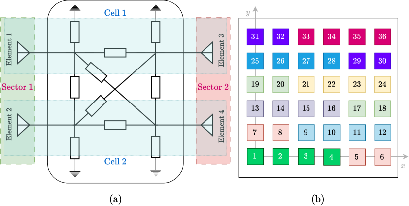
In this section, we explore the circuit structure and configuration strategy of the BD-RIS, concentrating on its design to enable efficient passive beamforming. A simplified example of the circuit structure for the fully-connected BD-RIS is presented in [22] and illustrated in Fig. 2(a). As detailed in Section II-A, the BD-RIS elements are divided into two sectors: sector 1, facing the active antenna, captures the incident EM wave, while sector 2, facing outward, transmits the directed signal toward the UE. Each pair of back-to-back elements from the two sectors forms a single cell, as depicted in Fig. 2(a).
To enable manipulation of both the amplitude and phase of the impinging EM wave, inter-element connections are crucial [12, 22]. Extending the two-cell structure in Fig. 2(a) to an -cell fully-connected BD-RIS significantly increases circuit complexity. To balance performance and circuit complexity, a -group-connected structure can be adopted by dividing the cells into groups, with each group containing cells. In this configuration, full connectivity is implemented within each group, while no connections exist between different groups [22]. For simplicity, we assume that all groups consist of an equal number of cells .111It is worth noting that varying grouping strategies with dynamic group sizes can lead to different trade-offs between performance and circuit complexity [40, 41]. However, investigating these strategies and their impact on passive beamforming performance lies beyond the scope of this paper and is deferred to future work. The set of cell indices for the -th group is defined as , where each group contains consecutive cells. This grouping approach is referred to as the linear permutation throughout this paper. To aid visualization, Fig. 2(b) illustrates a BD-RIS configuration with , , and . Two notable special cases arise from this framework:
-
•
When , the structure corresponds to a traditional transmissive RIS with a diagonal configuration scattering matrix, allowing only phase manipulation of the impinging signal, which limits its passive beamforming capabilities.
-
•
Conversely, when , the configuration transitions to a fully-connected BD-RIS, offering the highest degree of freedom for designing the configuration scattering matrix and enabling superior passive beamforming performance.
The configuration scattering matrix of the -th group, , is a full matrix that satisfies the following unitary and symmetry constraints:
| (12) |
| (13) |
The unitary constraint ensures that each group operates without power loss, while the symmetry constraint reduces hardware complexity by requiring only a single component between each pair of distinct elements.
The BS maintains direct access to the BD-RIS, enabling it to transmit control signals to an embedded controller for configuring the BD-RIS. To ensure compliance with the unitary and symmetry constraints for BD-RIS configuration as specified in (12) and (13), we utilize Takagi’s decomposition as outlined in [42]. Hence, utilizing the BS-RIS channel , the effective beamforming vector corresponding to the RIS-UE channel, and employing singular value decomposition (SVD) technique, the BD-RIS configuration for the general case of groups is detailed in Algorithm 1.
A critical factor influencing the BD-RIS configuration and overall system performance is the stochastic nature of the RIS-UE channel. To ensure effective performance, the BS must access the efficient beamforming vector which aligns with the RIS-UE channel during each time block. Obviously, the availability of CSI (full or partial) is crucial for deriving such an effective beamforming vector. In this paper, we evaluate the performance of the proposed system under three different cases based on CSI availability:
-
1.
Case 1 (Full CSI is available at the BS): The BS, equipped with a large antenna array, can estimate the RIS-UE channel by processing pilot signals transmitted by the UE during the uplink phase [21, 37, 38]. The optimal unconstrained beamforming vector for the channel is determined as , where represents the first column of the unitary matrix [36]. This matrix is obtained via the ordered SVD of the channel, expressed as , where is a vector of singular values with non-negative elements. The beamforming vector encapsulates the optimal complex weights—comprising both phase and magnitude—for the BD-RIS elements to maximize beamforming gain. However, in systems with constant modulus constraints, such as BS-integrated D-RIS or active analog beamforming antenna arrays utilizing analog phase shifter networks, only the phase information from can be exploited.
-
2.
Case 2 (Full CSI is available at the UE): In general, the UE may handle channel estimation;222Although this work focuses on an emulated MISO system, extending it to an emulated MIMO system with an additional BD-RIS integrated at the UE is straightforward. In such scenario, the UE would also be capable of performing channel estimation. however, feedbacking the full CSI to the BS, particularly in systems with massive MIMO, is often impractical and can result in significant overhead [36]. To address this, the UE can utilize the spatially sparse precoding (SSP) scheme proposed in [36]. With this approach, the UE identifies the best match for the channel’s dominant eigenmode from a predefined codebook. As the codebook is shared between the BS and UE, the UE only needs to transmit the index of the selected codeword, significantly reducing feedback overhead. In this paper, we utilize a codebook consisting of beams corresponding to equally spaced angles [36], defined as follows:
(14) The optimal beam alignment with is determined by identifying the beam index that maximizes the correlation, computed as:
(15) where and represent the -th and -th quantized azimuth and elevation angles within the ranges and , respectively. Subsequently, the UE transmits the indices to the BS via limited feedback link, allowing the BS to compute the beamforming vector as .
-
3.
Case 3 (Partial CSI is available): In certain scenarios, full CSI may be unavailable, or obtaining partial CSI is preferred to minimize channel estimation overhead [5, 9]. Angular channel information can be extracted using AoD estimation algorithms [43], allowing the identification of an effective transmission direction.333In order to emulate this process, we search across the available LOS and NLOS directions to maximize the transmitted signal in the target sub-channel while minimizing the leakage power into unintended sub-channels. Mathematically, the optimal direction is determined by solving ; hence, the effective beamforming vector can be obtained as . It is worth noting that the direction of the -th NLOS cluster is assumed to align with its best effective path, as defined in [1, equation (13)]. Subsequently, the effective channel , required for detection, can be readily estimated.
IV Channel Amplitude Variation: A Key Design Metric for BS-Integrated RIS Performance
In this section, we take a closer look at the design parameters of the BS-integrated BD-RIS and analyze how these parameters impact system performance compared to traditional structures. Specifically, we focus on the BS-RIS channel, a deterministic component of the BS’s internal architecture, shaped by the BS’s design parameters.
According to the Rayleigh-Sommerfeld diffraction theory for near-field propagation, as presented in (3), the amplitude of the channel coefficient corresponding to each element is inversely proportional to , emphasizing a rapid decay in channel gain amplitude with increasing distance. Unlike traditional D-RIS, which is limited to phase compensation, BD-RIS can adjust both phase and amplitude variations. Consequently, when the signal emitted by the active antenna reaches the BD-RIS, it achieves alignment in both phase and amplitude across RIS elements. The primary performance degradation in BS-integrated BD-RIS compared to active analog beamforming antenna arrays arises from the multiplicative path loss due to the BS-RIS distance. In contrast, D-RIS, with its phase-only adjustment capability, cannot align the amplitude variations across RIS elements. This limitation introduces additional performance degradation beyond the multiplicative path loss, as amplitude misalignment further reduces system efficiency. This enhanced capability of BD-RIS provides greater flexibility in beamforming design, whereas the performance of D-RIS remains fundamentally constrained by its limited adjustment capabilities.
Since amplitude variations across RIS elements play a crucial role, we focus on this aspect in the remainder of this section. As previously mentioned, the amplitude of the channel gain corresponding to the -th element is inversely proportional to . The variations in are significantly affected by two key factors: the array aperture and the BS-RIS separation (). The array aperture, directly proportional to the number of RIS elements, plays a crucial role—larger RIS arrays incorporate more elements, resulting in greater variations in and, consequently, more pronounced discrepancies in channel amplitudes across the elements. In contrast, as the BS-RIS separation () increases, the relative variations in decrease, leading to reduced differences in channel amplitudes among the RIS elements.
To quantify and visualize the relative spread of channel amplitude variations between the active antenna and the RIS elements, we introduce a novel metric called channel amplitude variation (CAV). CAV quantifies the variability in channel amplitudes relative to their mean and is specifically defined for the BS-RIS transmission channel vector . Mathematically, CAV is computed as the standard deviation of the channel amplitude components normalized by their mean, expressed as
| (16) |
where represents the mean amplitude of the channel gains between the active antenna and the RIS elements, and is formally expressed as
| (17) |
The normalization by the mean ensures that the CAV metric provides a dimensionless and scale-invariant representation of amplitude variability, making it suitable for comparisons across different system configurations and BS-RIS separations.
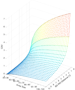
Fig. 3 depicts the CAV as a function of both the array size and the BS-RIS separation (). As previously discussed, the CAV increases with larger array sizes and smaller . It is important to note that the primary motivation for integrating RIS within the BS is to enable the implementation of larger arrays to achieve narrower beams, thereby reducing cost and power consumption. Additionally, minimizing the BS-RIS separation () is crucial to mitigate the impact of multiplicative path loss. Consequently, designing a system that aligns with these two characteristics is critical, underscoring the necessity of adopting BD-RIS to effectively manage amplitude variations. Notably, as decreases, placing the RIS closer to the active antenna, the CAV exhibits greater sensitivity, further underlining the importance of advanced designs like BD-RIS to mitigate these effects.
V Simulation Results and System Evaluation
This section presents the computer simulation results for the proposed BS-integrated BD-RIS, offering a comparative evaluation against considered benchmarks. The simulation setup is first outlined for a realistic mmWave street canyon environment. Next, the beamforming performance is assessed, demonstrating the potential of the BD-RIS to outperform the traditional D-RIS structure and closely rival the performance of active analog beamforming antenna arrays. ABER and achievable rate analyses are conducted under diverse circumstances to comprehensively evaluate the system’s performance from multiple perspectives. Finally, it is shown that dividing the BD-RIS cells into groups according to their geometric symmetry around the active antenna allows for a reduction in circuit complexity while maintaining system performance.
V-A Simulation Setup
We consider a P2P scenario in the street canyon environment which the distance between the BS-integrated BD-RIS and UE is considered m. We consider a carrier frequency of GHz; hence, we have a mmWave environment with a spatially sparse-scattered channel described in (4). Due to the highly dynamic nature of urban environments and the susceptibility of mmWave signals to blockages, the presence of a LOS path cannot be consistently guaranteed. To comprehensively evaluate the system’s performance under varying conditions, we consider two distinct scenarios:
-
•
Scenario 1: A dominant LOS component is present alongside several NLOS clusters.
-
•
Scenario 2: The LOS is blocked, and communication relies solely on the NLOS clusters to ensure connectivity.
| Parameter | Description | Value |
|---|---|---|
| Carrier frequency | GHz | |
| Communication bandwidth | MHz | |
| Communication range | m | |
| Inter-element spacing across and axis | ||
| BS-RIS separation | ||
| Area of each passive elements | ||
| BD-RIS size | ||
| Number of clusters | ||
| Number of paths per cluster | ||
| Angular spread in -th cluster | ||
| BS transmitted power | dBm | |
| -ary constellation order | ||
| Reference LOS path loss | dB | |
| Reference NLOS path loss | dB | |
| LOS path loss exponent | ||
| NLOS path loss exponent | ||
| LOS shadow fading severity | dB | |
| NLOS shadow fading severity | dB | |
| Noise PSD | Noise power spectrum density | dBm |
The path loss model for path is defined as follows [34]:
| (18) |
where represents the reference path loss at the reference distance, is the path loss exponent that determines the rate of signal attenuation with distance, and models the effect of shadowing, with indicating the shadow fading severity. The practical values for the parameters , , and are provided in Table I, derived from an experimental campaign conducted in a dense urban environment in New York City [34]. The noise power spectral density (PSD) is assumed to be [1, 39], and the system bandwidth (BW) is set to [1, 39]. Consequently, the noise power is calculated as . The number of NLOS clusters and paths is set to and , respectively, following the parameters in [1, 36]. The angular spread of the NLOS clusters is assumed to be as specified in [1]. Additionally, a binary phase shift keying (BPSK) signaling scheme is employed for ABER analysis. Unless specified otherwise, the default BD-RIS configuration in all simulations is fully-connected, showcasing the maximum potential of BD-RIS. A summary of the default system parameter values is presented in Table I.
To assess the performance of the proposed BS-integrated BD-RIS, we consider two benchmarks as outlined below:
- •
-
•
Benchmark 2 (Active Analog Beamforming Antenna Array): A BS configured with a planar active analog beamforming antenna array comprising elements connected to a network of analog single phase shifters [6]. In this configuration, the analog beamforming vector is directly applied to the phase shift network. It is important to note that the analog phase shift network imposes a constant modulus constraint on the beamforming weights. Consequently, when employing SVD, a phase-only beamforming vector is used, calculated as . The signal model corresponding to this benchmark can be expressed as:
(19)
V-B Beamforming Performance Analysis
This subsection evaluates the beamforming performance of the proposed BS-integrated BD-RIS under various system configurations, serving as a foundation for understanding the system’s behavior from other perspectives. As stated in (8), represents the effective beamforming vector at the RIS’s transmit terminal. Here, the matrix not only defines the RIS type (D-RIS or BD-RIS) but also specifies the grouping strategy employed in the BD-RIS configuration. To simplify the analysis, we consider a directional beam focused at as the beamforming vector for configuring the BD-RIS/D-RIS, defined as .
Fig. 4 presents the beamforming gain of the proposed BS-integrated BD-RIS compared with the benchmarks, i.e., the D-RIS and the active analog beamforming antenna array. Overall, increasing the array size results in sharper beams with higher directivity across all structures. However, the D-RIS exhibits lower directivity and broader beams compared to its counterparts, while the BD-RIS achieves a beamforming performance comparable to that of the active analog beamforming antenna array. This superior performance of the BD-RIS is attributed to its fully-connected structure, which enables it to effectively compensate for the CAV. The numerical metrics, including peak point (PP) directivity, half-power point (HPP) directivity, and half-power beamwidth (HPBW), extracted from Fig. 4 for various BS structures, are summarized in Table II.
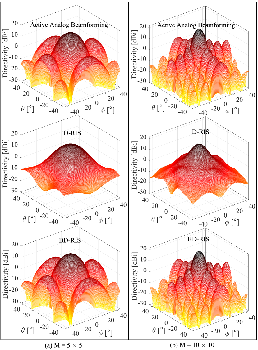
| Active Analog Beamforming | D-RIS | BD-RIS | ||||
| PP Directivity [dBi] | 15.1975 | 21.548 | 13.5771 | 17.6019 | 15.1975 | 21.548 |
| HPP Directivity [dBi] | 12.1186 | 18.6688 | 10.4215 | 14.6447 | 12.1186 | 18.6688 |
| HPBW [∘] | 21 | 10 | 27 | 15 | 21 | 10 |
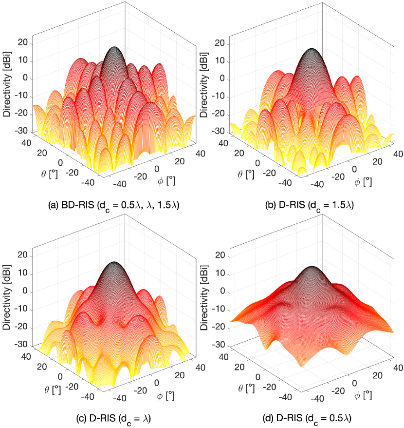
Fig. 5 illustrates the beamforming gain of the BS-integrated BD-RIS and D-RIS for varying BS-RIS separations (). Thanks to its ability to adjust both phase and amplitude, the BD-RIS maintains a consistent beam pattern regardless of , while the D-RIS demonstrates reduced directivity and increased HPBW as decreases. As shown in Fig. 3, the CAV increases as decreases, posing a challenge for D-RIS since it cannot compensate for the elevated CAV. The key beamforming metrics for these configurations are summarized in Table III. It is crucial to highlight that as increases, the multiplicative path loss becomes more pronounced, which detrimentally affects the overall system performance. Therefore, ensuring a high beamforming gain while minimizing is essential for optimizing performance, as elaborated in Section V-D.
| D-RIS | BD-RIS | |||
| PP Directivity [dBi] | 17.6019 | 20.0124 | 20.8684 | 21.548 |
| HPP Directivity [dBi] | 14.6447 | 17.0038 | 17.8702 | 18.6688 |
| HPBW (∘) | 15 | 13 | 12 | 10 |
V-C ABER Analysis
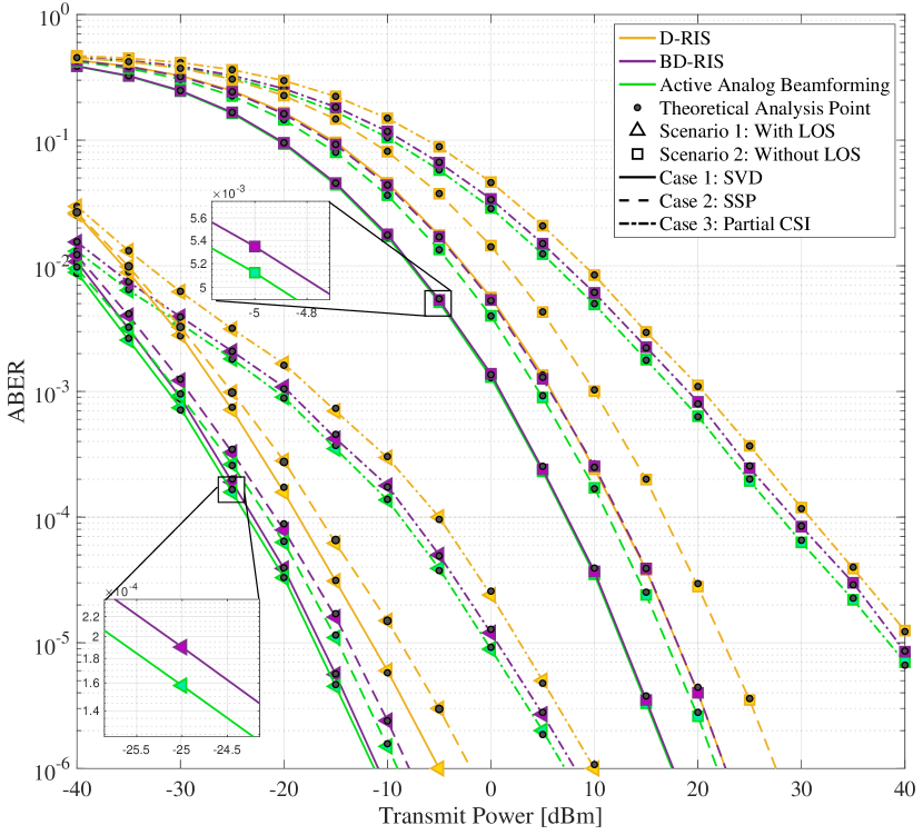
This subsection analyzes the ABER performance of the proposed BS-integrated BD-RIS across different LOS availability scenarios and three distinct precoding schemes. The results are benchmarked against D-RIS and active analog beamforming antenna arrays. Furthermore, as illustrated in Fig. 6, the theoretical bound derived in (11) provides a tight upper limit, validating the accuracy of our ABER simulations.
As shown in Fig. 6, the BD-RIS achieves performance close to that of the active analog beamforming antenna array across all evaluated scenarios and cases, demonstrating its robustness in delivering efficient beamforming gain under varying conditions. As outlined in Algorithm 1, the beamforming vector is employed in the BD-RIS configuration as a representation of the channel . Notably, in Case 1, incorporates both the amplitude and phase variations. However, only the BD-RIS can fully utilize these amplitude and phase variations, whereas the benchmarks, including the active analog beamforming antenna array, are restricted to exploiting only the phase components of . This capability provides the BD-RIS with one more advantage in Case 1, resulting in ABER performance that is closer to that of the active analog beamforming antenna array compared to other cases. In Scenario 2, where the channel is entirely composed of NLOS components, the amplitude variations across the RIS elements are more pronounced. This further improves the ABER performance of the BD-RIS in Case 1, narrowing the gap with the active analog beamforming antenna array even more compared to Scenario 1. In other cases, the performance gap between the BD-RIS and the active analog beamforming antenna array is solely attributed to the multiplicative path loss caused by the physical distance between the active antenna and the RIS elements.
On the other hand, the D-RIS, constrained to phase-only manipulation of the impinging signal, exhibits greater ABER performance degradation across various scenarios and cases due to both multiplicative path loss and reduced beamforming gain. As illustrated in Fig. 4 and summarized in Table II, the D-RIS generates wider beams, leading to increased signal leakage into unintended paths. Consequently, as a part of signal experiences higher fading in these unintended paths, the ABER increases for the D-RIS configuration.
These results highlight the limitations of D-RIS and underscore the significant advantages of BD-RIS in achieving efficient beamforming gain and improved ABER performance.
V-D Achievable Rate Analysis
This subsection provides a detailed analysis of the achievable rate performance as a function of transmit power, array size, and BS-RIS separation (). The achievable rate is calculated as follows:
| (20) |
where is the transmitted symbol following a complex normal distribution with unit variance, allowing the analysis to be generalized for any potential constellation.
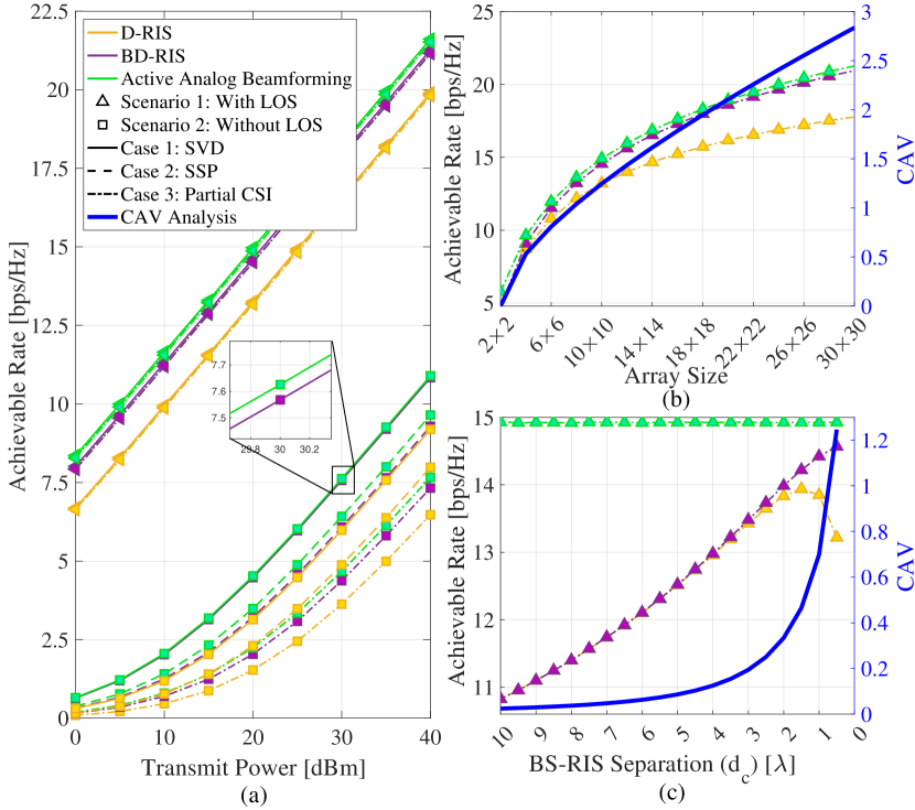
Fig. 7(a) illustrates the achievable rate as a function of transmit power across various scenarios and precoding cases. In all simulations, the BD-RIS demonstrates performance close to that of the active analog beamforming antenna array. Notably, in Scenario 2, where LOS is unavailable, and under Case 1, the BD-RIS achieves an achievable rate comparable to the active analog beamforming antenna array. As discussed in the previous subsection, the BD-RIS’s ability to manipulate both the phase and amplitude enables it to leverage the optimal phase and amplitude provided by . In contrast, the active analog beamforming antenna array is limited to utilizing only the phase information from the dominant eigenmode . This additional capability of the BD-RIS enhances its beamforming performance, allowing it to compensate for the multiplicative path loss and achieve comparable performance to the active analog beamforming antenna array in Scenario 2. Similar to the ABER performance, the reduced beamforming gain of the D-RIS leads to degraded achievable rate performance across all simulations.
It is worth noting that in the presence of a dominant LOS, as in Scenario 1, the achievable rate is identical across all precoding cases, as illustrated in Fig. 7(a). For the remainder of this paper, we focus on simulations conducted under Scenario 1 using Case 3, the less complex beamforming method. Fig. 7(b) presents the achievable rate (scaled on left -axis) as a function of the array size, alongside the corresponding CAV (blue curve scaled on right -axis), comparing the performance of the proposed BS-integrated BD-RIS against benchmark schemes. For a small RIS array of size , the BD-RIS and D-RIS exhibit identical performance. This is because, in this configuration, the distances between the active antenna and all RIS elements () are equal, resulting in uniform channel gain amplitudes across the elements; hence and there is no need for amplitude compensation. However, as the array size increases, the channel gain amplitudes across the RIS elements start to vary, as explained in Section IV. As shown in Fig. 7(b), larger array sizes lead to increased CAV, introducing greater discrepancies in channel gain amplitudes across RIS elements and emphasizing the need to compensate for these variations. Since the D-RIS cannot address amplitude variations, the performance gap between the D-RIS and the active analog beamforming antenna array widens with increasing array size. In contrast, the BD-RIS, with its ability to compensate for both amplitude and phase variations, maintains a constant performance gap compared to the active analog beamforming antenna array as the array size increases. As previously discussed, this constant gap is attributed to the multiplicative path loss.
The BS-RIS separation () is another critical factor influencing the CAV, as outlined in Section IV. To provide better insight, the CAV is plotted on the right -axis in Fig. 7(c), alongside the achievable rate (left -axis) for varying BS-RIS separation distances. As shown in Fig. 7(c), at sufficiently large separations, a reduction in generally leads to an increase in the achievable rate due to reduced multiplicative path loss. However, as decreases further, the D-RIS begins to exhibit noticeable performance degradation compared to the BD-RIS. This behavior arises because the increasing CAV at smaller values is more pronounced and demands compensation to maintain effective beamforming gain. While the BD-RIS, with its inter-element connections, can effectively mitigate amplitude variations, the D-RIS lacks this capability. As shown in Fig. 7(c), when falls below a certain threshold ( in the configuration considered here), the achievable rate performance of the D-RIS starts to decline with further decreasing . According to Fig. 5, the beamforming performance of the D-RIS deteriorates with decreasing , resulting in wider beams and reduced directivity. This suboptimal beamforming performance for leads to a decrease in the achievable rate for the D-RIS, as the negative impact of poor beamforming gain outweighs the positive effect of reduced multiplicative path loss. In contrast, the BD-RIS consistently demonstrates enhanced performance as decreases, attributed to its ability to effectively compensate for significant CAV and sustain robust beamforming. This enables the BD-RIS to fully capitalize on the reduced multiplicative path loss associated with smaller .
V-E Group-Connected BD-RIS Structure
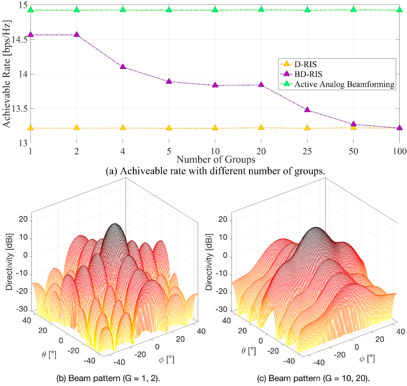
In this subsection, we examine the impact of the group-connected BD-RIS, which features a less complex circuit architecture compared to the fully-connected structure, on the achievable rate performance and beamforming gain of the proposed system. Fig. 8(a) illustrates the achievable rate performance for different numbers of groups. As the number of groups increases, the inter-element connections within each group decrease, as each fully-connected group comprises fewer elements. This reduction in inter-element connections lowers the circuit complexity but also reduces the degrees of freedom required to effectively compensate for the CAV, resulting in a degradation in achievable rate performance. However, certain special cases in Fig. 8(a) reveal an exception to this trend. Specifically, the performance remains identical for and , as well as for and .
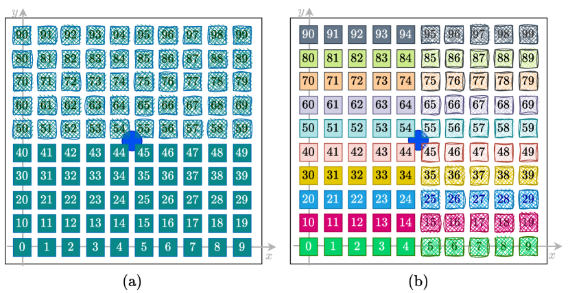
The reason for this behavior is illustrated in the beam patterns in Figs. 8(b) and (c). For and (Fig. 8(b)), the beam patterns are identical, and a similar observation holds for and (Fig. 8(c)). This phenomenon can be attributed to the geometric symmetry in the group configurations, as shown in Fig. 9. The blue circle in Fig. 9 denotes the location of the active antenna array, which is positioned at the back of the RIS at a distance from its center. In Fig. 9(a), a fully-connected structure is depicted, capable of compensating for CAV across the entire BD-RIS. However, this fully-connected structure can be divided into two groups for a -group-connected configuration, where one group is highlighted with solid colors, and the other is represented with cross-hatches. These groups exhibit geometric symmetry around the active antenna. Hence, it is evident that the set of values for each group is identical, leading to an equivalent CAV value for both groups. Furthermore, when these two sets are combined, the CAV of the entire BD-RIS remains equal to the CAV of each individual group. Consequently, a 2-group-connected BD-RIS structure with linear permutation suffices to effectively compensate for CAV across the entire BD-RIS.444Clearly, the 2-group-connected structure can be further divided into a 4-group-connected structure while maintaining identical CAV values due to the symmetry around the active antenna. However, achieving this requires more advanced permutations beyond the linear approach, which will be explored in our future work. Similarly, Fig. 9(b) illustrates a -group-connected structure, where the elements in each row are assigned to the same group. This structure can be further divided into two symmetric sub-groups around the active antenna, ensuring that the CAV values for each sub-group remain identical and equivalent to the original group. Consequently, inter-element connections can be minimized without compromising performance in such symmetric configurations.
It is worth noting that, as depicted in Fig. 9(b), the -group-connected structure incorporates inter-element connections exclusively along one dimension (the -axis), with no connections along the -axis. This configuration leads to a narrow HPBW in the elevation dimension while maintaining a broader beam in the azimuth dimension, as demonstrated in Fig. 8(b).
VI Conclusion
This paper studied a novel array architecture that enables passive beamforming at the BS, achieving beamforming gains comparable to those of active analog beamforming antenna arrays. By integrating the BD-RIS into the BS and leveraging its superior passive beamforming capability, a SISO system can emulate MISO performance. Our analysis demonstrated that the beamforming gain of the BS-integrated BD-RIS is robust to variations in RIS dimensions and BS-RIS separation, owing to its inter-element connection structure. In contrast, the performance of traditional D-RIS is highly sensitive to these critical design parameters. Consequently, the only notable performance degradation in the BS-integrated BD-RIS arises from the multiplicative path loss, which can be minimized by reducing the BS-RIS separation without concerns about beamforming degradation at short separations. To address circuit complexity, we proposed a simple grouping strategy that reduces the number of inter-element connections while maintaining equivalent beamforming performance. Comprehensive simulation results validated the efficiency of the proposed BS-integrated BD-RIS architecture and demonstrated its superiority over traditional D-RIS systems. Furthermore, it was shown that the proposed architecture achieves performance levels close to those of active analog beamforming antenna arrays, offering an affordable alternative in terms of cost and power consumption.
References
- [1] M. Raeisi, A. Koc, I. Yildirim, E. Basar, and T. Le-Ngoc, “Cluster index modulation for reconfigurable intelligent surface-assisted mmWave massive MIMO,” IEEE Trans. Wireless Commun., vol. 23, no. 2, pp. 1581–1591, Jul. 2023.
- [2] P. Wang, J. Fang, L. Dai, and H. Li, “Joint transceiver and large intelligent surface design for massive MIMO mmWave systems,” IEEE Trans. Wireless. Commun., vol. 20, no. 2, pp. 1052–1064, Oct. 2020.
- [3] M. Raeisi, A. Koc, E. Basar, and T. Le-Ngoc, “Cluster index modulation for mmWave communication systems,” Front. Comms. Net., Feb. 2022.
- [4] M. Mahmood, A. Koc, and T. Le-Ngoc, “3-D antenna array structures for millimeter wave multi-user massive mimo hybrid precoder design: A performance comparison,” IEEE Commun. Lett., Mar. 2022.
- [5] A. Koc, A. Masmoudi, and T. Le-Ngoc, “Angular-based 3D hybrid precoding for URA in multi-user massive MIMO systems,” in IEEE 90th Veh. Technol. Conf. (VTC2019-Fall), Honolulu, HI, USA, Sep. 2019, pp. 1–5.
- [6] X. Yu, J. Zhang, and K. B. Letaief, “A hardware-efficient analog network structure for hybrid precoding in millimeter wave systems,” IEEE J. Sel. Top. Signal Process., vol. 12, no. 2, pp. 282–297, Mar. 2018.
- [7] E. Basar, M. Di Renzo, J. De Rosny, M. Debbah, M.-S. Alouini, and R. Zhang, “Wireless communications through reconfigurable intelligent surfaces,” IEEE Access, vol. 7, pp. 116 753–116 773, Aug. 2019.
- [8] M. Raeisi, A. Khaleel, M. C. Ilter, M. Gerami, and E. Basar, “A comprehensive design framework for UE-side and BS-side RIS deployments,” arXiv preprint arXiv:2404.16607, 2024.
- [9] A. Koc and T. Le-Ngoc, “Hybrid millimeter-wave massive MIMO systems with low CSI overhead and few-bit DACs/ADCs,” in IEEE 92nd Veh. Technol. Conf. (VTC2020-Fall), Dec. 2020, pp. 1–5.
- [10] Z. Zhang, L. Dai, X. Chen, C. Liu, F. Yang, R. Schober, and H. V. Poor, “Active RIS vs. passive RIS: Which will prevail in 6G?” IEEE Trans. Commun., vol. 71, pp. 1707–1725, Dec. 2022.
- [11] W. Khalid, Z. Kaleem, R. Ullah, T. V. Chien, S. Noh, and H. Yu, “Simultaneous transmitting and reflecting-reconfigurable intelligent surface in 6G: Design guidelines and future perspectives,” IEEE Network, pp. 1–9, Dec. 2022.
- [12] H. Li, S. Shen, M. Nerini, and B. Clerckx, “Reconfigurable intelligent surfaces 2.0: Beyond diagonal phase shift matrices,” IEEE Commun. Mag., vol. 62, no. 3, pp. 102–108, Nov. 2023.
- [13] J. An et al., “Stacked intelligent metasurface-aided MIMO transceiver design,” IEEE Wireless Commun., vol. 31, no. 4, pp. 123–131, Apr. 2024.
- [14] K. Liu, Z. Zhang, and L. Dai, “User-side RIS: Realizing large-scale array at user side,” in IEEE Glob. Commun. Conf. (GLOBECOM), Dec. 2021, pp. 01–06.
- [15] K. Liu, Z. Zhang, L. Dai, and L. Hanzo, “Compact user-specific reconfigurable intelligent surfaces for uplink transmission,” IEEE Trans. Commun., vol. 70, no. 1, pp. 680–692, Nov. 2022.
- [16] Y. Huang, L. Zhu, and R. Zhang, “Integrating intelligent reflecting surface into base station: Architecture, channel model, and passive reflection design,” IEEE Trans. Commun., vol. 71, no. 8, pp. 5005–5020, 2023.
- [17] W. Du, Z. Chu, G. Chen, P. Xiao, Z. Lin, C. Huang, and W. Hao, “Hybrid beamforming design for ITS-assisted wireless networks,” IEEE Wireless Commun. Lett., vol. 12, no. 3, pp. 451–455, Mar. 2023.
- [18] Q. Li, M. El-Hajjar, C. Xu, J. An, C. Yuen, and L. Hanzo, “Stacked intelligent metasurfaces for holographic MIMO-aided cell-free networks,” IEEE Trans. Commun., vol. 72, no. 11, pp. 7139–7151, May 2024.
- [19] J. An, M. Di Renzo, M. Debbah, and C. Yuen, “Stacked intelligent metasurfaces for multiuser beamforming in the wave domain,” in IEEE Int. Conf. Commun. (ICC), Rome, Italy, May. 28 - Jun. 01, 2023, pp. 2834–2839.
- [20] Z. Li, J. An, and C. Yuen, “Stacked intelligent metasurfaces for fully-analog wideband beamforming design,” in IEEE VTS Asia Pac. Wireless Commun. Symp. (APWCS), Singapore, Aug. 2024.
- [21] X. Yao, J. An, L. Gan, M. Di Renzo, and C. Yuen, “Channel estimation for stacked intelligent metasurface-assisted wireless networks,” IEEE Wireless Commun. Lett., vol. 13, no. 5, pp. 1349–1353, Feb. 2024.
- [22] H. Li, S. Shen, and B. Clerckx, “Beyond diagonal reconfigurable intelligent surfaces: From transmitting and reflecting modes to single-, group-, and fully-connected architectures,” IEEE Trans. Wireless Commun., vol. 22, no. 4, pp. 2311–2324, Oct. 2023.
- [23] ——, “Beyond diagonal reconfigurable intelligent surfaces: A multi-sector mode enabling highly directional full-space wireless coverage,” IEEE Journal on Selected Areas in Communications, vol. 41, no. 8, pp. 2446–2460, 2023.
- [24] S. Shen, B. Clerckx, and R. Murch, “Modeling and architecture design of reconfigurable intelligent surfaces using scattering parameter network analysis,” IEEE Trans. Wireless Commun., vol. 21, no. 2, pp. 1229–1243, Aug. 2022.
- [25] A. Mishra, Y. Mao, C. D’Andrea, S. Buzzi, and B. Clerckx, “Transmitter side beyond-diagonal reconfigurable intelligent surface for massive MIMO networks,” IEEE Wireless Commun. Lett., vol. 13, no. 2, pp. 352–356, Nov. 2024.
- [26] K. Chen and Y. Mao, “Transmitter side beyond-diagonal RIS for mmWave integrated sensing and communications,” in IEEE 25th Int. Workshop Signal Process. Adv. Wireless Commun. (SPAWC), Sep. 2024, pp. 951–955.
- [27] M. Nerini and B. Clerckx, “Physically consistent modeling of stacked intelligent metasurfaces implemented with beyond diagonal RIS,” IEEE Commun. Lett., vol. 28, no. 7, pp. 1693–1697, May 2024.
- [28] M. Raeisi, H. Chen, H. Wymeersch, and E. Basar, “Efficient localization with base station-integrated beyond diagonal RIS,” arXiv preprint arXiv:2411.13295, 2024.
- [29] M. Raeisi, A. Koc, I. Yildirim, E. Basar, and T. Le-Ngoc, “Antenna array structures for enhanced cluster index modulation,” in Joint Eur. Conf. Netw. Commun. & 6G Summit (EuCNC/6G Summit), Gothenburg, Sweden, 06 – 09 Jun. 2023, pp. 102–107.
- [30] J. An et al., “Stacked intelligent metasurfaces for efficient holographic MIMO communications in 6G,” IEEE J. Sel. Areas Commun., vol. 41, no. 8, pp. 2380–2396, Jun. 2023.
- [31] H. Niu et al., “Stacked intelligent metasurfaces for integrated sensing and communications,” IEEE Wireless Commun. Lett., vol. 13, no. 10, pp. 2807–2811, Aug. 2024.
- [32] J. An et al., “Two-dimensional direction-of-arrival estimation using stacked intelligent metasurfaces,” IEEE J. Sel. Areas Commun., vol. 42, no. 10, pp. 2786–2802, Jun. 2024.
- [33] H. Liu, J. An, D. W. K. Ng, G. C. Alexandropoulos, and L. Gan, “DRL-Based orchestration of multi-user MISO systems with stacked intelligent metasurfaces,” in IEEE Int. Conf. Commun. (ICC), 09-13 Jun. 2024, pp. 4991–4996.
- [34] M. R. Akdeniz, Y. Liu, M. K. Samimi, S. Sun, S. Rangan, T. S. Rappaport, and E. Erkip, “Millimeter wave channel modeling and cellular capacity evaluation,” IEEE J. Sel. Areas Commun., vol. 32, no. 6, pp. 1164–1179, Jun. 2014.
- [35] K. Ying, Z. Gao, S. Lyu, Y. Wu, H. Wang, and M.-S. Alouini, “GMD-based hybrid beamforming for large reconfigurable intelligent surface assisted millimeter-wave massive MIMO,” IEEE Access, vol. 8, pp. 19 530–19 539, 2020.
- [36] O. El Ayach, S. Rajagopal, S. Abu-Surra, Z. Pi, and R. W. Heath, “Spatially sparse precoding in millimeter wave MIMO systems,” IEEE Trans. Wireless Commun., vol. 13, no. 3, pp. 1499–1513, Jan. 2014.
- [37] Ö. T. Demir, E. Björnson, and L. Sanguinetti, “Channel modeling and channel estimation for holographic massive MIMO with planar arrays,” IEEE Wireless Commun. Lett., vol. 11, no. 5, pp. 997–1001, Feb. 2022.
- [38] M. Cui and L. Dai, “Channel estimation for extremely large-scale MIMO: Far-field or near-field?” IEEE Trans. Commun., vol. 70, no. 4, pp. 2663–2677, Jan. 2022.
- [39] M. Raeisi, I. Yildirim, M. C. Ilter, M. Gerami, and E. Basar, “Plug-in RIS: A novel approach to fully passive reconfigurable intelligent surfaces,” IEEE Trans. Wireless Commun., vol. 23, no. 10, pp. 14 776–14 789, Jul. 2024.
- [40] M. Nerini, S. Shen, H. Li, and B. Clerckx, “Beyond diagonal reconfigurable intelligent surfaces utilizing graph theory: Modeling, architecture design, and optimization,” IEEE Trans. Wireless Commun., vol. 23, no. 8, pp. 9972–9985, Feb. 2024.
- [41] H. Li, S. Shen, and B. Clerckx, “A dynamic grouping strategy for beyond diagonal reconfigurable intelligent surfaces with hybrid transmitting and reflecting mode,” IEEE Trans. Veh. Technol., vol. 72, no. 12, pp. 16 748–16 753, Jun. 2023.
- [42] I. Santamaria, M. Soleymani, E. Jorswieck, and J. Gutiérrez, “SNR maximization in beyond diagonal RIS-assisted single and multiple antenna links,” IEEE Signal Process. Lett., vol. 30, pp. 923–926, Jul. 2023.
- [43] A. Koc, A. Masmoudi, and T. Le-Ngoc, “3D angular-based hybrid precoding and user grouping for uniform rectangular arrays in massive MU-MIMO systems,” IEEE Access, vol. 8, pp. 84 689–84 712, May 2020.
- [44] Ö. T. Demir and E. Björnson, “User-centric cell-free massive MIMO with RIS-integrated antenna arrays,” in IEEE 25th Int. Workshop Signal Process. Adv. Wireless Commun. (SPAWC), Sep. 2024, pp. 546–550.
- [45] J. An et al., “Stacked intelligent metasurface performs a 2D DFT in the wave domain for DOA estimation,” in IEEE Int. Conf. Commun. (ICC), Jun. 2024, pp. 3445–3451.