STAR-RIS-Enabled Multi-Path Beam Routing with Passive Beam Splitting
Abstract
Reconfigurable intelligent surfaces (RISs) or intelligent reflecting surfaces (IRSs) can be densely deployed in the environment to create multi-reflection line-of-sight (LoS) links between base stations (BS) and users, thereby significantly enhancing the BS coverage. However, conventional reflection-only RISs can only achieve half-space reflection, which limits the LoS path diversity. In contrast, simultaneously transmitting and reflecting reconfigurable intelligent surfaces (STAR-RISs) can split incident signals into reflected and transmitted signals pointing to different half spaces simultaneously, thereby creating more LoS paths. Hence, in this paper, we study a new multi-STAR-RIS-aided communication system, where a multi-antenna BS transmits to multiple single-antenna users by exploiting the signal beam routing over a set of cascaded LoS paths each formed by multiple STAR-RISs. To reveal essential insights, we first consider a simplified single-user case, aiming to maximize its received signal power by jointly optimizing the active beamforming at the BS, the BS’s power allocation over different paths, the number of selected beam-routing paths, the selected STAR-RISs for each path, as well as their amplitude and phase shifts for transmission/reflection. However, this problem is particularly difficult to be optimally solved as different paths may be intricately coupled at their shared STAR-RISs. To tackle this difficulty, we first derive the optimal solutions to this problem in closed-form for a given set of paths. The clique-based approach in graph theory is then applied to solve the remaining multi-path selection problem efficiently. Next, we extend the proposed clique-based method to the more general multi-user case to maximize the minimum received signal power among all users, subject to additional constraints on the disjointness of the selected paths for different users. Simulation results show that our proposed STAR-RIS-enabled beam routing outperforms the conventional beam routing with reflection-only RISs in both single- and multi-user cases.
Index Terms:
Simultaneously transmitting and reflecting reconfigurable intelligent surface (STAR-RIS), multi-path beam routing, passive beam splitting, graph theory.I Introduction
Reconfigurable intelligent surfaces (RISs) or intelligent reflecting surfaces (IRSs) have gained significant attention as a cutting-edge technology in the sixth-generation (6G) wireless communication systems. The RIS/IRS is able to proactively reshape the signal propagation environment by dynamically adjusting the phase-shifts of its large number of passive reflecting elements. Moreover, the RIS/IRS can operate without the need of active radio-frequency (RF) chains for transmitting or receiving signals, which substantially reduces the hardware cost and energy consumption compared to traditional active transceivers and relays [2, 3, 4, 5, 6]. These attractive benefits of RISs/IRSs have spurred considerable enthusiasm in investigating their optimal reflection or passive beamforming designs in various wireless systems in the past several years (see e.g., [2, 3, 4, 5, 6, 7, 8, 9, 10] and the references therein).
However, existing works on RISs/IRSs have mostly focused on the single-reflection links by one or multiple RISs but ignored the more general multi-RIS-reflection links, which can also be utilized to further improve the end-to-end channel condition. For example, in a complex environment with dense obstacles, multi-RIS reflections can create more available cascaded line-of-sight (LoS) links to bypass the obstacles between the base station (BS) and remote user locations, thereby significantly enhancing the BS’s signal coverage. Moreover, multiple RISs can cooperatively reflect the signal over each cascaded LoS path, providing pronounced cooperative passive beamforming (CPB) gain to compensate for the severe multiplicative path loss over it [11]. Hence, multi-IRS-reflection aided wireless communication systems have been studied in several prior works. For example, to improve the coverage range of Terahertz (THz) communications, the authors of [12] proposed a deep reinforcement learning (DRL)-based approach to jointly optimize the CPB of multiple RISs in a given multi-RIS-reflection link. To more effectively exploit the multi-IRS-induced LoS path diversity, some existing works [13, 14, 15, 16, 17, 18, 19, 20, 21, 22, 23, 24] have delved into a new cooperative beam routing problem. Specifically, the authors of [13, 14, 15, 16] aimed to select an optimal multi-RIS-reflection path from the BS to each user and jointly optimize the BS/RIS active/passive beamforming in each selected path, such that the end-to-end BS-user channel power gain is maximized. A more general multi-path beam routing scheme was introduced in [17], where multiple paths can be selected for each user by exploiting the active/passive beam splitting/combining at the BS/each user. Furthermore, the authors of [18] proposed a joint resource allocation and multi-path beam routing scheme to further improve the performance of multi-user communication systems. Unlike the above works focusing on passive RISs only that may suffer high multiplicative path loss in the multi-hop reflection, the authors of [19] investigated a general multi-active and multi-passive-RIS enabled beam routing problem, where multiple active RISs were introduced to enhance the strength of the multi-reflection links by leveraging their amplification capability. Besides, the authors of [20] studied a new cooperative dual-polarized RIS-aided communication system and its associated beam-routing path selection problem. On the other hand, the authors of [21, 22, 23, 24] have conducted performance analysis of various metrics of multi-RIS-reflection communication systems, e.g., ergodic capacity, average symbol error probability, outage probability and sum rate.
However, all of the above studies only focused on conventional reflection-only RISs that can only achieve half-space reflection, severely limiting the LoS path diversity. To overcome this limitation, a new type of RIS, known as simultaneously transmitting and reflecting RIS (STAR-RIS), has been introduced recently, which is able to achieve 360∘ full-space manipulation of the impinging signal. In particular, the incident signal to each STAR-RIS element from either side can be split into a reflected signal and a refracted/transmitted signal pointing to different half spaces at the same time (referred to as passive beam splitting in this paper) [25, 26, 27]. As such, by exploiting the passive beam splitting of multiple STAR-RISs, it is anticipated that more cascaded LoS paths can be created compared to conventional reflection-only RISs. Note that single-hop STAR-RISs have been extensively studied in the literature. For example, the authors of [28] aimed to jointly optimize the transmit and reflect beamforming of a STAR-RIS in both non-orthogonal multiple access (NOMA) and orthogonal multiple access (OMA) systems. To maximize the sum rate of multiple users, the authors of [29] jointly optimized the placement of multiple STAR-RISs and their passive beamforming. Furthermore, the authors of [30, 31, 32, 33, 34, 35] analyzed different performance metrics of the STAR-RIS-aided NOMA system, e.g., outage probability, ergodic rate, throughput and sum-rate. Different from previous works assuming independent phase-shift control for transmission and reflection, the authors of [36] developed a more practical coupled transmission and reflection phase-shift model and studied its associated power consumption minimization problem. The authors of [37] proposed to mount the STAR-RIS on an unmanned aerial vehicle (UAV) and jointly optimized the UAV’s trajectory and active beamforming, as well as the passive transmission/reflection beamforming of the STAR-RIS to maximize the sum-rate of multiple ground users. The authors of [38] proposed a STAR-RIS-enabled integrated sensing and communications (ISAC) framework with a novel sensing-at-STAR-RIS structure. Despite the extensive prior works on single-hop STAR-RISs, there is no existing work focusing on the use of STAR-RISs for multi-hop beam routing, to the best of our knowledge.
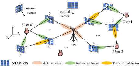
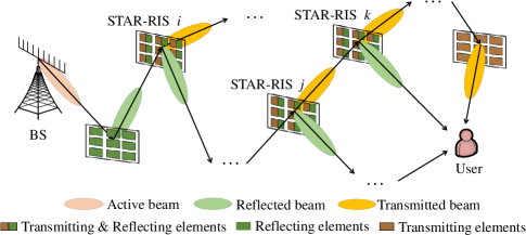
To fill in this gap, we investigate a multi-STAR-RIS-aided wireless communication system and its beam routing design, as shown in Fig. 1. In particular, we consider the multicast transmission from a multi-antenna BS to multiple single-antenna users via a set of multi-hop paths each formed by multiple STAR-RISs. The main contributions of this paper are summarized as follows.
-
•
First, to reveal essential insights into the STAR-RIS-enabled beam routing, we consider a simplified single-user scenario. With a goal to maximize the received signal power at the user, we jointly optimize the BS’s active beamforming, the number of beam-routing paths, the BS’s power allocation over different paths, the selected STAR-RISs in each path, as well as their transmission/reflection amplitudes and phase shifts. Nevertheless, compared to the beam-routing optimization for conventional reflection-only RISs in [13, 14, 15, 16, 17, 18, 19, 20], the beam-routing problem for STAR-RISs appears to be more difficult to be optimally solved as the paths may be intricately coupled at their shared STAR-RISs. To tackle this difficulty, we first derive the optimal solution to this problem in closed-form for a given set of paths, which reveals that the maximum achievable rate at the single user is equal to the sum of the maximum channel power gains for the selected paths. Furthermore, we employ a clique-based approach based on graph theory to solve the remaining multi-path selection problem efficiently via partial enumeration.
-
•
Next, we extend the above STAR-RIS-enabled multi-path beam routing scheme to a more general multi-user scenario by selecting disjoint beam-routing paths for different users. Compared to the single-user case, we further optimize the power allocations for different users at the BS to maximize the minimum received signal powers among them, subject to additional constraints on the disjointness of the selected paths for different users. We derive the optimal power allocation for multiple users in closed-form given other optimization variables and apply the clique-based method to obtain a high-quality suboptimal solution for the multi-user beam-routing. Numerical results demonstrate that our proposed STAR-RIS-enabled beam routing scheme significantly outperforms the conventional beam routing schemes with reflection-only RISs for both single- and multi-user system setups by offering a more pronounced LoS path diversity gain.
The rest of this paper is organized as follows. Section II presents the system model. Section III presents a simplified case with a single user and the associated beam-routing design. Section IV presents the more general multi-user case. Section V presents the numerical results to show the efficacy of the proposed schemes. Section VI concludes this paper and discusses future works.
| Number of BS antennas | Number of users | ||||||
| Number of STAR-RISs | Number of elements per STAR-RIS | ||||||
| Set of users | Set of STAR-RISs | ||||||
| Active beamforming vector of the BS | Distance between nodes and | ||||||
| Reflection/transmission amplitude of STAR-RIS |
|
||||||
|
|
||||||
| LoS graph of the system | Vertex/edge set of | ||||||
| Normal vector of STAR-RIS | Direction vector from node to node | ||||||
| Edge from vertex to vertex in | Channel from the BS to STAR-RIS | ||||||
| Channel from STAR-RIS to STAR-RIS | Channel from STAR-RIS to user | ||||||
| BS-user channel over path | LoS path gain over path | ||||||
| Maximum end-to-end channel power gain over path | Total transmit power allocated to the -th active beam | ||||||
| BS beamforming vector for the -th active beam | -th path associated with the -th active beam | ||||||
|
Number of selected STAR-RISs in | ||||||
| Index of the -th STAR-RIS in | Set of the nodes before/after STAR-RIS | ||||||
| In/Out-degree of node | Set of nodes with out-degree equal to 2 | ||||||
| Cosine of the angle between and |
|
|
|||||
|
|
|
|
Maximum value of | ||||
| Set of all selected STAR-RISs |
|
||||||
| -th reflected/transmitted path in |
|
||||||
|
Number of candidate paths selected for each user | ||||||
| Path graph of the considered system | -th active beam associated with user | ||||||
|
|
||||||
| Number of active beams associated with user | Total transmit power allocated to user |
The following notations are used in this paper. Bold symbols in capital letter and small letter denote matrices and vectors, respectively. The conjugate, transpose and conjugate transpose of a vector or matrix are denoted by , and , respectively. ( ) denotes the set of real (complex) vectors of length . For a complex number , and denote its conjugate and amplitude, respectively. For a diagonal matrix , denotes an vector that contains the diagonal elements of . denotes the imaginary unit, i.e., . For two sets and , denotes their union. denotes an empty set. denotes the angle between vector and vector . For ease of reference, the main symbols used in this paper are listed in Table I.
II System Model
As shown in Fig. 1, we consider the multicast transmission111The proposed scheme is also applicable to the scenarios of wireless power transfer and of broadcast transmission (subjected to more stringent constraints on the path separation among the users for interference mitigation [14]). from a BS equipped with antennas to single-antenna users with the aid of STAR-RISs. Due to the dense obstacles in the environment, we assume that the BS can only transmit to each user through one or more LoS links each formed by multiple STAR-RISs, as shown in Fig. 1. We denote the sets of all users, STAR-RISs and the reflecting/transmitting elements per STAR-RIS as , and , respectively, and let be the number of elements of each STAR-RIS per dimension. For convenience, we refer to the BS, STAR-RIS and user as nodes , and , respectively. Given a reference point at the BS and each STAR-RIS, we establish a global coordinate system for the considered system and denote the three-dimensional (3D) coordinate of the reference point of node as . As such, the distance between any two nodes and can be expressed as . Moreover, we consider that the transmitted signal can only be reflected/transmitted from one STAR-RIS (e.g., STAR-RIS ) to a farther STAR-RIS from the BS (e.g., STAR-RIS with ), but not vice versa, to ensure the outward signal transmission/reflection and avoid the severe multiplicative path loss[11].
As shown in Fig. 1, we consider that all STAR-RISs are operated in the ES protocol[25, 26, 27], where each STAR-RIS element can reflect and transmit its incident signal at the same time. For each STAR-RIS , let the amplitude and phase-shift of its -th element for reflection be denoted as and , respectively, with and . To ease the hardware implementation, we also assume that all elements of STAR-RIS share a common amplitude for reflection, i.e., . As such, the reflection coefficient matrix of STAR-RIS can be written as , where denotes its reflection phase-shift matrix. Similarly, we express the transmission coefficient matrix of STAR-RIS by replacing the superscripts “” above with “” as , where denotes its transmission phase-shift matrix. Due to the law of energy conservation, we have .
To leverage the pronounced LoS diversity gain by densely deploying the STAR-RISs, we assume that only LoS links can be selected for the multi-hop transmission from the BS to the users via the STAR-RISs, while all non-LoS (NLoS) links can be treat as part of environment scattering, which only have marginal effect on the received signal power at each user in general[39, 14]. To describe all cascade LoS paths from the BS to all users efficiently, we define a LoS graph for all nodes and their pairwise LoS links, denoted as , where and denote the sets of vertices and edges in , respectively. We add an edge from vertex to vertex , denoted as , if the following two conditions are satisfied: 1) there exists a LoS path from node to node , and 2) node is farther away from the BS than node , i.e., for routing signal outwards from the BS except that node is a user. As such, each multi-hop path from the BS to user corresponds to a path from vertex 0 to vertex in . For example, in Fig. 1, the path from the BS to user 1 going through STAR-RISs 1 and 2 corresponds to the path 0 1 2 .
Next, we characterize the end-to-end channel from the BS to user in any given multi-hop LoS path, denoted as with , where and denote the number of STAR-RISs in and the index of the -th STAR-RIS in this path, and we set and . Notably, the selected STAR-RISs in may use different surfaces to either reflect or transmit their respective incoming signals, depending on the locations of its previous and next nodes. For example, if nodes and are located on the same side/different sides of STAR-RIS , its reflection/transmission surface should be used to reflect/transmit the incident signal from node to node . To determine the used surface of any STAR-RIS given its previous and next nodes, we define a normal vector for each STAR-RIS , denoted as , which is perpendicular to its surface and points to the half-space where the BS is located, as shown in Fig. 1. Furthermore, we define the direction vector from node to node as with , . Hence, the cosine of the angle between and can be expressed as . Then, it can be shown that nodes and are located at the same side of STAR-RIS if and only if , which may occur if or . While if , they should be located at different sides of STAR-RIS 222Note that we have assumed that any normal vector is non-orthogonal to any direction vector, i.e., , by properly deploying the STAR-RISs.. For example, in Fig. 1, we have , indicating that STAR-RIS 2 and 3 are located at different sides of STAR-RIS 1.
Assume that the BS and each STAR-RIS are equipped with a uniform linear array (ULA) and a uniform rectangular array (URA) parallel to the plane, respectively, as shown in Fig. 1. Let denote the channel from the BS to STAR-RIS , denote that from STAR-RIS to STAR-RIS , and denote that from STAR-RIS to user . Note that the above channels are applicable to both the reflection and transmission sides of each STAR-RIS. Under the far-field propagation, if , i.e., an LoS path is available from the BS to STAR-RIS , the BS-STAR-RIS channel is given by , where , and denote the path gain at the reference distance of one meter (m), the array response from the BS to STAR-RIS and that at STAR-RIS from the BS, respectively. Similarly, if , the STAR-RIS -STAR-RIS and STAR-RIS -user channels can be expressed as and , respectively, where , and are their corresponding array responses. Denote by , and the angle-of-departure (AoD) from the BS to STAR-RIS , the azimuth/elevation AoD from STAR-RIS to node (STAR-RIS or the user) and the azimuth/elevation angle-of-arrival (AoA) at STAR-RIS from node (STAR-RIS or BS), respectively. Then, assuming far-field propagation between any two nodes, we have
where denotes the -th entry of a vector , , , , and . Moreover, , , and denote the carrier wavelength, the BS’s antenna spacing, and the STAR-RIS’s element spacing, respectively.
We define and as the cascaded LoS path gain and the propagation distance from the BS to user over , respectively. Let denote the BS’s transmit beamforming vector with . Then, the BS-user end-to-end channel over the path is given by
| (1) |
where
| (2) |
and
| (3) |
indicates the used surface of STAR-RIS in path . For example, in Fig. 1, the reflection surface of STAR-RIS 1 is used in the path 0 1 3 8 (user 1) while its transmission surface is used in the path 0 1 2 8 (user 1).
To maximize the BS-user channel power gain for any given transmission/reflection amplitude of the STAR-RIS over , i.e., , the active BS beamforming and the phase-shifts of each STAR-RIS should be set as[13]
| (4) |
| (5) |
where we define as the optimal active beamforming vector for the BS to transmit to STAR-RIS with and as the optimal phase-shift for STAR-RIS to reflect/transmit the beam from its previous node to next node with . Based on (4) and (5), and can reach their maximum values of and , respectively. Given the amplitude , by substituting (4) and (5) into (1), the maximum BS-user channel power gain over the path can be obtained as
| (6) |
Furthermore, we denote the maximum end-to-end channel power gain of as
| (7) |
which is achieved by setting Evidently, we have
In our previous works [13, 14, 17, 18], we have shown how to select multiple node-disjoint paths from the BS to the user for multi-path routing in the case with conventional reflection-only RISs. However, the STAR-RISs may be involved in multiple paths at the same time for simultaneous transmission and reflection. As such, a new multi-path beam routing scheme should be designed for STAR-RISs. Next, to reveal essential insights, we first focus on a simplified single-user case and compare the associated beam-routing design with that for conventional reflection-only RISs.
III Multi-path Beam Routing with Passive Beam Splitting for a Single user
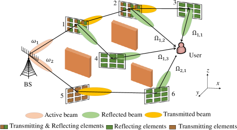
In this section, we first focus on a simple scenario with a single user (i.e. ), as shown in Fig. 2. In our proposed STAR-RIS-enabled multi-path beam routing, the BS splits its beamforming vector, , into multiple active beams via its active beam splitting, each successively transmitted and/or reflected by the selected STAR-RISs, thereby creating more split paths via passive beam splitting. Finally, the signals over all split paths are coherently combined at the user’s receiver. The details are presented below.
III-A Active and Passive Beam Splitting
First, we assume that the BS splits its beamforming vector into beams and denote by the -th split beam, . Let denote the proportion of the total transmit power allocated to the -th active beam with . As such, the BS’s active beamforming can be expressed as .
For each split active beam , it may be split into two beams if it is transmitted and reflected at the same time by a STAR-RIS. The resulted two passive beams may be split into more beams by other STAR-RISs, which give rise to more end-to-end LoS paths. For example, in Fig. 2, the beam is split at STAR-RIS 1 into two beams, one of which is further split at STAR-RIS 2, thus creating three LoS paths from the BS to the user, i.e., , and . As such, the beam is associated with these three paths. Assume that each split active beam is associated with paths and denote the -th path as , , where and denote the index of the -th used STAR-RIS in and the total number of selected STAR-RISs in this path, respectively.
Let the set of all selected STAR-RISs be denoted as and define . For each STAR-RIS , we denote the set of its previous nodes and next nodes as and , respectively. As such, we can express the number of previous and next nodes of STAR-RIS , (a.k.a. the in-degree and out-degree of node ) as and , respectively. To simplify the optimization, we assume that each selected STAR-RIS only reflect or/and transmit an incident signal from one previous node to one or two next nodes located at its different sides, i.e.,
| (8) |
It is worth noting that only when STAR-RIS reflects and transmits its incident signal at the same time, we have . Let denote the set of selected STAR-RISs with their out-degree equal to 2. For example, in Fig. 2, we have . For each STAR-RIS , as its two next nodes should be located at its different sides, it must hold that
| (9) |
III-B Optimal STAR-RIS Phase Shifts and BS Power Allocation
Next, we show that given the paths , , , we can obtain the optimal STAR-RIS phase shifts for transmission/reflection (i.e., and , ) and the BS power allocation (i.e., ) in closed form. Specifically, given (8) and (9), it is noted that the transmission and reflection phase shifts of each STAR-RIS can be determined only based on its channels with one previous node and one next node, respectively, similarly to (5). For example, in Fig. 2, the transmission phase shifts of STAR-RIS 2 only depend on STAR-RISs 1 and 3, while its reflection phase shifts only depend on STAR-RIS 1 and the user. As such, the optimal phase shifts of the STAR-RISs in can be obtained based on (5) by replacing the nodes in with those in , and the resulting channel power gain can be obtained as similar to (6). By setting the reflection/transmission amplitude of all STAR-RISs in to unity, its maximum channel power gain is given by .
Notably, the signals over the paths may not coherently add at the user’s receiver because of their different time delays causing random channel phases. To maximize the received power, a phase rotation should be appended to any STAR-RIS in the path to ensure that signals over different paths are coherently combined. The value of rotated phases can be computed by the BS based on distributed beam training[39]. As such, the received power at the user can be expressed as
| (10) |
where and the inequality is according to the Cauchy-Schwarz inequality. Note that to make the equality in (10) hold, we should set
| (11) |
III-C Optimal STAR-RIS Amplitudes
Next, we derive the optimal reflection and transmission amplitude of each STAR-RISs in . We start from the simple example shown in Fig. 2(a), where the BS splits its beamforming vector into active beams (i.e. and ) transmitted to the user via the STAR-RISs deployed between them. The active beam is further split by STAR-RIS 1 and STAR-RIS 2, resulting in three split paths denoted as , and . Thus, we have with , and . Similarly, for the active beam , we have and where . Note that for the STAR-RISs that are only involved in a single path, their reflect/transmit amplitude should be set to unity to maximize the received power at the user, as either their reflection or transmission surfaces are used. For example, in Fig. 2, we set , , and to unity. By substituting the above into (10), the received power at the user can be expressed as
| (12) |
where the inequality is due to the Cauchy-Schwarz inequality, and the last equality is due to the fact that and . Moreover, it can be shown that by setting the amplitudes of each STAR-RIS , as follows, the equality in (12) can always hold.
| (13) | ||||
The result in (12) indicates that the maximum received signal power with the optimal amplitude of the selected STAR-RISs is equal to the sum of the channel power gains over the paths , , , and . Next, we extend this observation to a general setup. To this end, we first define any end-to-end path as a transmitted/reflected path for STAR-RIS , if this path goes through its transmission/reflection surface. For example, in Fig. 2, and are the transmitted paths of STAR-RIS 1 while is its reflected path. Accordingly, we can denote the set of reflected paths and transmitted paths for each STAR-RIS , as and , respectively, where and , denote the -th reflected/transmitted path and the number of reflected/transmitted paths going through STAR-RIS , respectively. Note that if only the reflect or transmit surface of STAR-RIS is used, the set or should be set to , respectively. To proceed, we propose the following proposition.
Proposition 1
Proposition 1 indicates that the maximum received signal power is equal to the sum of the maximum channel power gains of the selected paths, as if they were node disjoint. This suggests that the enhanced LoS path diversity gain and the coherent beam combining at the user can effectively compensate for the loss of the maximum CPB gain over each path resulted from the passive beam splitting. The result in (14) also greatly simplifies the remaining path selection optimization, as detailed next. It is also worth noting that to achieve the received signal power in (14), we assume that its corresponding optimal phase-shift and amplitude designs in (4), (5), and (15) are already available at the BS. In practice, they can be acquired by leveraging the offline beam training among the adjacent STAR-RISs thanks to the quasi-static BS-STAR-RIS and inter-STAR-RIS LoS channels, as well as their beam training with the user in real time [39]. This paper serves as an initial work characterizing the theoretical performance limit of multi-STAR-RIS-enabled beam routing, and more detailed investigation into the cooperative beam training scheme for multiple STAR-RISs can be pursued as a future work.
III-D Problem Formulation
In this paper, we aim to jointly optimize the number of the active beams () and their associated paths (, ), as well as the selected STAR-RISs in each of these paths (’s) to maximize the received signal power in (14). The associated optimization problem is formulated as
It is noted that by only constraining and removing (9) in , all beam-routing paths will become node-disjoint, such that each selected STAR-RIS can only either reflect or transmit the incident signal, i.e., it works based on the mode selection (MS) protocol[25, 26, 27]. As such, the optimal value of should be no smaller than that achieved by STAR-RISs in the MS protocol. However, is a more challenging combinatorial optimization problem due to the intricate coupling of the paths at their shared STAR-RISs in (instead of being node-disjoint as in [17]). Next, we propose an efficient graph-based solution to solve it.
III-E Proposed Solution to (P1)
Specifically, we adopt a clique-based approach in graph theory to solve (P1) via partial enumeration. First, among all paths from vertex to vertex in , we select candidate paths that achieve the largest maximum end-to-end channel power gains, i.e., . To this end, we can define a weight for each in . Then, it can be shown that finding the paths with the largest maximum end-to-end channel power gain is equivalent to finding the paths with the smallest sum of edge weights in [13]. This is a classical graph-theoretical problem that can be optimally solved by invoking Yen’s algorithm [40], which incurs the complexity in the order of [40]. Denote by the set of all candidate paths. From the paths in , we aim to find the best set of paths that is feasible to (P1) and achieves the maximum objective value.
To achieve this purpose, we can construct a path graph , where each vertex in corresponds to one candidate paths in . To ensure that any selected paths satisfy the constraints in (P1), we add an edge to any two vertices in if and only if the nodes of their corresponding paths in satisfy the constraints in (P1). To proceed, we present the definitions of clique and maximal clique in the graph theory.
Definition 1
A clique refers to a subset of vertices of an undirected graph such that every two distinct vertices in the clique are adjacent.
Definition 2
A maximal clique refers to a clique that cannot be extended by including one more adjacent vertex, that is, a clique which does not exist exclusively within the vertex set of a larger clique.
Based on Definition 1, a clique with vertices corresponds to a feasible solution to (P1) with paths. Hence, we can enumerate all cliques in to obtain all paths sets and select the best one. However, based on Definition 2, there is no need to enumerate all possible cliques and we only need to enumerate the maximal cliques in . This is because for any clique in (e.g., ), if it is not a maximal clique, there must exist another clique with , which means that the corresponding paths in should also be a subset of those in . Hence, the latter must yield a better performance than the former because more paths are constructed to serve the user. We apply the Bron-Kerbosch algorithm [40] to enumerate the maximal cliques in , with the required worst-case computational complexity in the order of . Note that if the number of the candidate paths is sufficiently large, the optimal path solution to may be included in . In this case, the proposed approach can achieve globally optimal performance, at the cost of higher time complexity. Fortunately, as will be shown in Section V-A via simulation, it generally only requires a small to achieve the optimal performance. Finally, we compare the objective value of achieved by each maximal clique in and select the corresponding paths of the best one as the output.
IV Proposed Scheme for Multiple Users
In this section, we extend the proposed scheme in Section III to the multicast scenario with multiple users.
IV-A Optimal Phase Shifts and Amplitude for Multiple STAR-RISs
First, we assume that the BS splits its active beamforming vector into beams, and each user is associated with active beams each going through paths, , with . Denote the -th path of the -th active beam for user as , where and denote the index of the -th STAR-RIS in and the total number of selected STAR-RISs in this path, respectively. To simplify the optimization and facilitate the use of the proposed scheme in Section III, we assume that the selected paths for different users are node-disjoint, i.e., if , while the paths selected for each user can be intersected subjected to (8) and (9). Given the above constraints and the paths , , , , it follows that the reflection/transmission amplitude and phase-shifts designs of STAR-RISs associated with different users can be decoupled. As such, we can obtain the optimal reflection/transmission phase-shifts of each STAR-RIS in a path similarly to (5) by replacing the nodes in with those in .
Specifically, we define as the -th active split beam transmitted to user . Let and denote the proportion of the total transmit power allocated to the -th user and the -th active beam of user , respectively, with and . As such, the BS’s active beamforming vector can be expressed as . Since all users share no common STAR-RISs and paths, Proposition 1 should hold for each user for any selected paths. As a result, the maximum received signal power at user for any given path selection can be expressed as
| (16) |
IV-B Problem Formulation
In the multicast scenario, we aim to maximize the minimum received signal power among all users by jointly optimizing the selected STAR-RISs, i.e., ’s, the number of active beams for each user and their associated paths , as well as the multi-user power allocation . The corresponding optimization problem is formulated as
| (17) | ||||
Compared to (P1), (P2) is more challenging to be optimally solved due to the presence of more users and the additional constraints on the disjointness of their selected paths and power allocations. On the other hand, compared to the multi-user beam routing problems studied in our previous works[17, 14, 18] for conventional reflection-only RISs, (P2) is also more complicated due to the coupled paths at their shared STAR-RISs. In the following, we propose a clique-based solution to (P2) via partial enumeration as well.
IV-C Proposed Solution to (P2)
First, we determine the optimal power allocation solution to (P2), i.e., , for any given path selection. It can be shown that at the optimality of (P2), it must hold that the received signal powers of all users, i.e. , are identical. Based on this fact, we can obtain
| (18) |
which results in
| (19) |
Based on (19), (P2) can be equivalently recast as
| (20) | ||||
To solve (P3), we adopt a similar clique-based algorithm to Section III-E. Due to the presence of multiple users, for each user , , we first select candidate paths from vertex 0 to vertex with the largest maximum end-to-end power gains by invoking Yen’s algorithm[40], which incurs the complexity in the order of . Denote by and the set of candidate paths for user and the set of all candidate paths with .

Among all paths in , we aim to find the best set of paths that is feasible to (P3) and achieves the minimum objective value. To this end, we construct a path graph including all candidate paths in (instead of ), i.e., , with denoting the vertex corresponding to path . Next, we add an edge between any two vertices in , e.g., and , if and only if the corresponding paths in satisfy the constraints in (P3). Similarly, each clique in corresponds to a feasible solution to (P3) and it suffices to find the maximal cliques in . We apply the Bron-Kerbosch algorithm[40] to enumerate the maximal cliques in . The worst-case computational complexity is on the order of . Finally, we compare the objective value of (P3) achieved by each maximal clique in and select the best one as the output. Note that if the number of candidate paths is sufficiently large, the optimal solution should be included at th cost of higher complexity.
V Numerical Results
In this section, numerical results are provided to demonstrate the efficacy of our proposed STAR-RIS-enabled multi-beam routing. We set the number of the BS’s antennas and the operating carrier frequency as and GHz, respectively, leading to dB. The number of elements in each dimension of the STAR-RISs is assumed to be identical to . For performance comparison, we consider two benchmark schemes with STAR-RISs in the MS mode (labeled as Benchmark 1) and conventional reflection-only RISs (labeled as Benchmark 2), respectively.
V-A Single-User Case
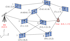
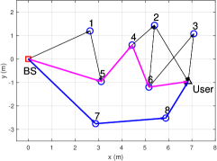
As shown in Fig. 3, we consider STAR-RISs between the BS and user, and their 3D coordinates and formed LoS graph are shown in Fig. 3(a) and Fig. 3(b), respectively. For Benchmark 2, its corresponding LoS graph can be obtained by removing the edges , , , , , and in Fig. 3(b).
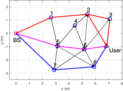
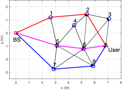
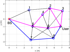
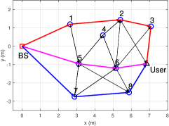
First, we study the optimized reflection paths by the proposed scheme and the two benchmark schemes for 14 and 16 in Fig 4. It is observed from Figs. 4(a)-4(c) that under , the proposed scheme yields the maximum number (i.e., 4) of reflected paths from the BS to the user, while Benchmark 2 yields the minimum number (i.e., 2). This is expected as the proposed scheme can yield the highest LoS path diversity gain among the three schemes by leveraging the simultaneous signal reflection and transmission in the 360∘ full-space. The conventional reflection-only RISs can only achieve signal reflection in the 180∘ half-space, thus resulting the lowest LoS path diversity. It is also observed that the reflected paths in the proposed scheme include those in Benchmark 1 by further utilizing the transmission function of STAR-RIS 4. However, this does not hold for , as observed from Figs. 4(d)-4(f). Moreover, it is also observed that the selected reflected paths by all considered schemes under generally go through more hops of STAR-RISs compared to , so as to better exploit the more significant CPB gain with increasing .
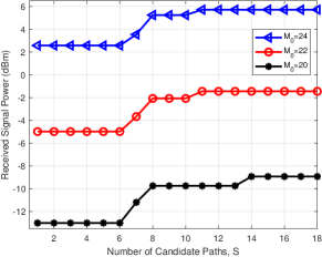
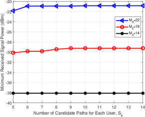
Next, in Fig. 5, we study the received signal power at the user versus the number of candidate paths under different values of . It is observed that the received signal power at the user is non-increasing with thanks to the enlarged solution set for path selection. However, the received signal power cannot be further increased by increasing when , 8 and 9 under 20, 22, and 24, respectively, which implies that the optimal path selection is likely to be achieved by the proposed algorithm under a relatively small .
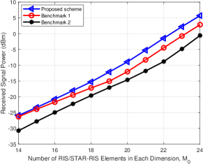
In Fig. 6, we study the received signal power at the user versus by different schemes. It is observed that our proposed scheme outperforms the two benchmarks over the whole range of considered. Particularly, the performance gain over Benchmark 1 is observed to become more significant for a larger and can approach 5 dB when . The possible reason is that each reflected path may go through more STAR-RISs with increasing , thus imposing more stringent constraints on the two benchmarks for selecting node-disjoint paths. In contrast, the proposed scheme allows for the selection of coupled paths and thus is less affected by increasing .
V-B Multi-User Case
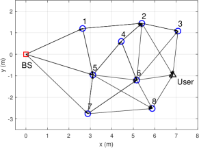
In this subsection, we consider users with the aid of STAR-RISs, and their 3D coordinates are shown in Fig. 7(a). The associated LoS graph is shown in Fig. 7(b).
In Fig. 8, we study the selected paths by the proposed scheme and the two benchmark schemes for and 18 in the multi-user case. It is observed that similar to the single-user case, the proposed scheme yields the largest number of paths for each user among the considered schemes thanks to its highest LoS path diversity. In contrast, Benchmark 2 yields the minimum number of paths due to its lowest LoS path diversity with half-space reflection constraint. In particular, in the MS mode, it is observed from Figs. 8(b) and 8(e) that the number of selected paths for users 1 and 2 may affect each other. As a result, one of users 1 and 2 is served by two paths, while the other is only served by a single path. Unlike the MS mode, the proposed algorithm can assign 4 paths for user 1 and 2 paths for user 2, thereby greatly improving their communication performance. It is also observed that when increases, the selected paths go through more hops of STAR-RISs to enjoy the higher CPB gain, which is consistent with the observation made in Fig. 10. Furthermore, it is observed that the selected reflected paths by the proposed scheme ensure separation among all users, which manifests the effectiveness of our proposed clique-based algorithm.
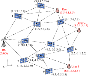
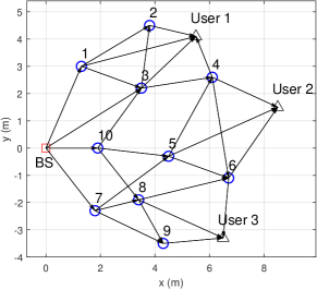

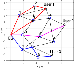
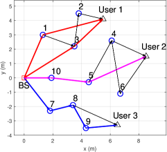
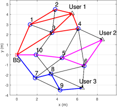
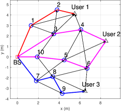

Fig. 9 shows the max-min received signal power versus the number of candidate paths selected for each user, . It is observed that the max-min received signal power cannot be further improved by increasing the number of candidate paths when , 9 and 6 under , 18 and 22, respectively, implying that the optimal solution may have been achieved by the proposed algorithm with a relatively small even in the multi-user case. This thus ensures the scalability of our proposed beam-routing scheme with increasing the number of users.
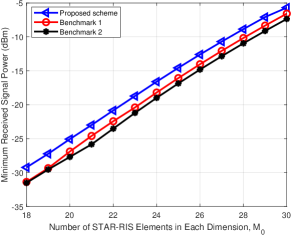
Finally, in Fig. 10, we study the max-min received signal power among all users versus the number of RIS/STAR-RIS elements in each dimension . It is observed that the performance by all schemes increases with thanks to the increased CPB gain. Moreover, our proposed scheme outperforms two benchmarks over the whole range of considered. In particular, Benchmark 1 with the MS mode is observed to even achieve the same performance as Benchmark 2 with reflection-only RISs as is small. In contrast, the proposed scheme can achieve 2-3 dB higher max-min received signal power compared to the two benchmark schemes for all .
VI Conclusion
In this paper, we proposed a multi-STAR-RIS enabled multi-path beam routing scheme for a multi-user communication system. First, we focused on a simplified single-user system setup and derived the optimal active beamforming and power allocation at the BS, as well as the optimal amplitude and phase-shifts for both transmission and reflection in closed form for a given path selection. The results unveil that the maximum received signal power at the user can be expressed as the sum of the maximum channel power gains of the selected paths as if they were disjoint. A clique-based algorithm was then proposed to obtain a near-optimal solution for the path selection problem. Next, we extended our proposed methods to the multicast scenario subject to additional node-disjoint constraints on the selected paths for different users. Numerical results demonstrate that the proposed algorithm can achieve near-optimal performance and exploiting STAR-RISs for beam routing can achieve a considerably better performance compared to conventional reflection-only RISs by reaping more pronounced LoS path diversity gain. This paper can be extended in several directions for future work. For example, it is worthy of studying a hybrid active and passive STAR-RIS system to further compensate for the cascaded path losses due to multi-hop signal transmission/reflection. Moreover, how to extend the cooperative beam training scheme designed for RISs to STAR-RISs to facilitate their beam-routing design is also an interesting and practically relevant problem to be studied.
[Proof of Proposition 1] To derive the optimal reflected and transmitted amplitude of STAR-RIS , we first denote the product of the amplitude of STAR-RIS ’s subsequent nodes over each reflected/transmitted path as , . Note that only when the path going through STAR-RIS is further split into more paths by its subsequent nodes, we have . Evidently, for STAR-RIS with , we have because only one reflected/transmitted path goes through it without passive beam splitting. Note that if there is no subsequent node after STAR-RIS , can be set to unity. For example, in Fig. 2, we have , , for STAR-RIS 1 and for STAR-RIS 2.
As shown in Fig. 11, we assume that the -th active beam is first split at STAR-RIS . Since the previous nodes only reflect/transmit the signal, the product of their amplitudes should be unity, and the sum of channel power gains over all paths associated with the -th active beam is expressed as
| (21) |
where and the inequality is due to the Cauchy-Schwarz inequality. Note that each path associated with the -th active beam corresponds to one reflected/transmitted path of STAR-RIS . As such, (14) can be proved if we can prove
| (22) |
where . Next, we prove (22) for each selected STAR-RIS via induction. First, we validate (22) in the case shown in (22) with and 2. Then, we assume that (22) always holds when , with . Finally, we prove that (22) still holds when . The details are as follows.
First, it can be observed that the example shown in Fig. 2 can satisfy (22), i.e., with , with and , with and , with , as well as with and . Next, we assume that for any STAR-RIS with , (22) always holds. Then, we consider STAR-RIS with .
For STAR-RIS with , assuming that node is its first subsequent node, , we have
| (23) |
It is evident that we have with and . Accordingly, (23) can be written as
| (24) |
where the last equality is because each path going through the transmission/reflection surface of STAR-RIS (i.e. ) corresponds to a transmitted/reflected path of STAR-RIS (i.e. ). Hence, (22) is proved. Moreover, it can be shown that by setting
the equality in (23) can always hold. Given (22), for the -th active beam, (21) can be written as
| (25) |
Then, considering all active beams, we have . This thus completes the proof.
References
- [1] B. An and W. Mei, “STAR-RIS-enabled multi-path beam routing with passive beam splitting,” in Proc. IEEE Glob. Commun. Conf., Cape Town, South Africa, Dec. 2024, pp. 3553–3558.
- [2] Q. Wu, S. Zhang, B. Zheng, C. You, and R. Zhang, “Intelligent reflecting surface-aided wireless communications: A tutorial,” IEEE Trans. Commun., vol. 69, no. 5, pp. 3313–3351, May 2021.
- [3] Y. Liu, X. Liu, X. Mu, T. Hou, J. Xu, M. Di Renzo, and N. Al-Dhahir, “Reconfigurable intelligent surfaces: Principles and opportunities,” IEEE Commun. Surveys Tuts., vol. 23, no. 3, pp. 1546–1577, 3rd Quart. 2021.
- [4] M. D. Renzo et al., “Smart radio environments empowered by reconfigurable AI meta-surfaces: An idea whose time has come,” EURASIP J. Wireless Commun. Netw., vol. 2019, no. 1, pp. 1–20, May 2019.
- [5] Q. Wu and R. Zhang, “Towards smart and reconfigurable environment: Intelligent reflecting surface aided wireless network,” IEEE Commun. Mag., vol. 58, no. 1, pp. 106–112, 2020.
- [6] E. Basar, M. Di Renzo, J. De Rosny, M. Debbah, M.-S. Alouini, and R. Zhang, “Wireless communications through reconfigurable intelligent surfaces,” IEEE Access, vol. 7, pp. 116 753–116 773, 2019.
- [7] M. Di Renzo, A. Zappone, M. Debbah, M.-S. Alouini, C. Yuen, J. De Rosny, and S. Tretyakov, “Smart radio environments empowered by reconfigurable intelligent surfaces: How it works, state of research, and the road ahead,” IEEE J. Sel. Areas Commun., vol. 38, no. 11, pp. 2450–2525, 2020.
- [8] X. Yuan, Y.-J. A. Zhang, Y. Shi, W. Yan, and H. Liu, “Reconfigurable-intelligent-surface empowered wireless communications: Challenges and opportunities,” IEEE Wireless Commun., vol. 28, no. 2, pp. 136–143, 2021.
- [9] C. Pan, G. Zhou, K. Zhi, S. Hong, T. Wu, Y. Pan, H. Ren, M. Di Renzo, A. L. Swindlehurst, R. Zhang et al., “An overview of signal processing techniques for RIS/IRS-aided wireless systems,” IEEE J. Sel. Topics Signal Process., vol. 16, no. 5, pp. 883–917, 2022.
- [10] B. Zheng, C. You, W. Mei, and R. Zhang, “A survey on channel estimation and practical passive beamforming design for intelligent reflecting surface aided wireless communications,” IEEE Commun. Surveys Tuts., vol. 24, no. 2, pp. 1035–1071, 2022.
- [11] W. Mei, B. Zheng, C. You, and R. Zhang, “Intelligent reflecting surface-aided wireless networks: From single-reflection to multireflection design and optimization,” Proc. IEEE, vol. 110, no. 9, pp. 1380–1400, 2022.
- [12] C. Huang, Z. Yang, G. C. Alexandropoulos, K. Xiong, L. Wei, C. Yuen, Z. Zhang, and M. Debbah, “Multi-hop RIS-empowered terahertz communications: A DRL-based hybrid beamforming design,” IEEE J. Sel. Areas Commun., vol. 39, no. 6, pp. 1663–1677, 2021.
- [13] W. Mei and R. Zhang, “Cooperative beam routing for multi-IRS aided communication,” IEEE Commun. Lett., vol. 10, no. 2, pp. 426–430, 2020.
- [14] W. Mei and R. Zhang, “Multi-beam multi-hop routing for intelligent reflecting surfaces aided massive MIMO,” IEEE Trans. Wireless Commun., vol. 21, no. 3, pp. 1897–1912, 2021.
- [15] X. Ma, Y. Fang, H. Zhang, S. Guo, and D. Yuan, “Cooperative beamforming design for multiple RIS-assisted communication systems,” IEEE Trans. Wireless Commun., vol. 21, no. 12, pp. 10 949–10 963, 2022.
- [16] Y. Wu, T. Zhao, H. Hai, and E. Bai, “An index modulation system for multi-IRS aided communication,” IEEE Commun. Lett., vol. 29, no. 1, pp. 6–10, 2025.
- [17] W. Mei and R. Zhang, “Intelligent reflecting surface for multi-path beam routing with active/passive beam splitting and combining,” IEEE Commun. Lett., vol. 26, no. 5, pp. 1165–1169, May 2022.
- [18] W. Mei, D. Wang, Z. Chen, and R. Zhang, “Joint beam routing and resource allocation optimization for multi-IRS-reflection wireless power transfer,” IEEE Trans. Wireless Commun., vol. 23, no. 11, pp. 16 606–16 620, 2024.
- [19] Y. Zhang and C. You, “Multi-hop beam routing for hybrid active/passive IRS aided wireless communications,” in Proc. IEEE Glob. Commun. Conf., Rio de Janeiro, Brazi, Dec. 2022, pp. 3138–3143.
- [20] A. Bhowal and S. Aïssa, “MIMO device-to-device communications via cooperative dual-polarized intelligent surfaces,” IEEE Wireless Commun. Lett., vol. 12, no. 2, pp. 202–206, 2023.
- [21] D. Tyrovolas, S. A. Tegos, E. C. Dimitriadou-Panidou, P. D. Diamantoulakis, C. K. Liaskos, and G. K. Karagiannidis, “Performance analysis of cascaded reconfigurable intelligent surface networks,” IEEE Wireless Commun. Lett., vol. 11, no. 9, pp. 1855–1859, 2022.
- [22] Z. Zhakipov, K. M. Rabie, X. Li, and G. Nauryzbayev, “Accurate approximation to channel distributions of cascaded RIS-aided systems with phase errors over nakagami-m channels,” IEEE Wireless Commun. Lett., vol. 12, no. 5, pp. 922–926, 2023.
- [23] Y. Wang, W. Zhang, Y. Chen, C.-X. Wang, and J. Sun, “Novel multiple RIS-assisted communications for 6g networks,” IEEE Commun. Lett., vol. 26, no. 6, pp. 1413–1417, 2022.
- [24] Y. Liu, L. Zhang, F. Gao, and M. A. Imran, “Intelligent reflecting surface networks with multiorder-reflection effect: System modeling and critical bounds,” IEEE Trans. Commun., vol. 70, no. 10, pp. 6992–7005, 2022.
- [25] X. Mu, Y. Liu, L. Guo, J. Lin, and R. Schober, “Simultaneously transmitting and reflecting (STAR) RIS aided wireless communications,” IEEE Trans. Wireless Commun., vol. 21, no. 5, pp. 3083–3098, May 2021.
- [26] Y. Liu, X. Mu, J. Xu, R. Schober, Y. Hao, H. V. Poor, and L. Hanzo, “STAR: Simultaneous transmission and reflection for 360° coverage by intelligent surfaces,” IEEE Wireless Commun., vol. 28, no. 6, pp. 102–109, 2021.
- [27] X. Mu, J. Xu, Z. Wang, and N. Al-Dhahir, “Simultaneously transmitting and reflecting surfaces for ubiquitous next-generation multiple access in 6g and beyond,” Proc. IEEE, vol. 112, no. 9, pp. 1346–1371, 2024.
- [28] J. Zuo, Y. Liu, Z. Ding, L. Song, and H. V. Poor, “Joint design for simultaneously transmitting and reflecting (STAR) RIS assisted NOMA systems,” IEEE Trans. Wireless Commun., vol. 22, no. 1, pp. 611–626, Jan. 2023.
- [29] C. Wu, Y. Liu, X. Mu, X. Gu, and O. A. Dobre, “Coverage characterization of STAR-RIS networks: NOMA and OMA,” IEEE Commun. Lett., vol. 25, no. 9, pp. 3036–3040, Sep. 2021.
- [30] X. Yue, J. Xie, Y. Liu, Z. Han, R. Liu, and Z. Ding, “Simultaneously transmitting and reflecting reconfigurable intelligent surface assisted NOMA networks,” IEEE Trans. Wireless Commun., vol. 22, no. 1, pp. 189–204, 2023.
- [31] R. Zhong, X. Mu, Y. Liu, Y. Chen, J. Zhang, and P. Zhang, “STAR-RISs assisted NOMA networks: A distributed learning approach,” IEEE J. Sel. Topics Signal Process., vol. 17, no. 1, pp. 264–278, 2023.
- [32] Q. Gao, Y. Liu, X. Mu, M. Jia, D. Li, and L. Hanzo, “Joint location and beamforming design for STAR-RIS assisted NOMA systems,” IEEE Trans. Commun., vol. 71, no. 4, pp. 2532–2546, 2023.
- [33] M. Aldababsa, A. Khaleel, and E. Basar, “STAR-RIS-NOMA networks: An error performance perspective,” IEEE Commun. Lett., vol. 26, no. 8, pp. 1784–1788, 2022.
- [34] X. Li, Y. Zheng, M. Zeng, Y. Liu, and O. A. Dobre, “Enhancing secrecy performance for STAR-RIS NOMA networks,” IEEE Trans. Veh. Technol., vol. 72, no. 2, pp. 2684–2688, 2023.
- [35] F. Karim, S. K. Singh, K. Singh, S. Prakriya, and M. F. Flanagan, “On the performance of STAR-RIS-aided NOMA at finite blocklength,” IEEE Wireless Commun. Lett., vol. 12, no. 5, pp. 868–872, 2023.
- [36] Y. Liu, X. Mu, R. Schober, and H. V. Poor, “Simultaneously transmitting and reflecting (STAR)-RISs: A coupled phase-shift model,” in Proc. IEEE Int. Conf. Commun., Seoul, Republic of Korea, May 2022, pp. 2840–2845.
- [37] J. Zhao, Y. Zhu, X. Mu, K. Cai, Y. Liu, and L. Hanzo, “Simultaneously transmitting and reflecting reconfigurable intelligent surface (STAR-RIS) assisted UAV communications,” IEEE J. Sel. Areas Commun., vol. 40, no. 10, pp. 3041–3056, 2022.
- [38] Z. Wang, X. Mu, and Y. Liu, “STARS enabled integrated sensing and communications,” IEEE Trans. Wireless Commun., vol. 22, no. 10, pp. 6750–6765, 2023.
- [39] W. Mei and R. Zhang, “Distributed beam training for intelligent reflecting surface enabled multi-hop routing,” IEEE Wireless Commun. Lett., vol. 10, no. 11, pp. 2489–2493, 2021.
- [40] D. B. West et al., Introduction to graph theory. Prentice hall Upper Saddle River, 2001, vol. 2.