33email: suparna.kundu@esat.kuleuven.be, 33email: ghosh69@purdue.edu, 33email: angshuman@cse.iitk.ac.in, 33email: shreyas@purdue.edu, 33email: ingrid.verbauwhede@esat.kuleuven.be
Rudraksh: A compact and lightweight post-quantum key-encapsulation mechanism
Abstract
Resource-constrained devices such as wireless sensors and Internet of Things (IoT) devices have become ubiquitous in our digital ecosystem. These devices generate and handle a major part of our digital data. However, due to the impending threat of quantum computers on our existing public-key cryptographic schemes and the limited resources available on IoT devices, it is important to design lightweight post-quantum cryptographic (PQC) schemes suitable for these devices.
In this work, we explored the design space of learning with error-based PQC schemes to design a lightweight key-encapsulation mechanism (KEM) suitable for resource-constrained devices. We have done a scrupulous and extensive analysis and evaluation of different design elements, such as polynomial size, field modulus structure, reduction algorithm, and secret and error distribution of an LWE-based KEM. Our explorations led to the proposal of a lightweight PQC-KEM, Rudraksh, without compromising security. Our scheme provides security against chosen ciphertext attacks (CCA) with more than 100 bits of Core-SVP post-quantum security and belongs to the NIST-level-I security category (provide security at least as much as AES-128). We have also shown how ASCON can be used for lightweight pseudo-random number generation and hash function in the lattice-based KEMs instead of the widely used Keccak for lightweight design. Our FPGA results show that Rudraksh currently requires the least area among the PQC KEMs of similar security. Our implementation of Rudraksh provides a improvement in terms of the area requirement compared to the state-of-the-art area-optimized implementation of Kyber, can operate at - higher frequency with respect to high-throughput Kyber, and improves time-area-product compared to the state-of-the-art compact implementation of Kyber published in HPEC 2022.
keywords:
Post-quantum cryptography, key-encapsulation mechanism, Lightweight cryptography, Lattice-based cryptography, Hardware implementation, FPGA.1 Introduction
Lightweight cryptography (LWC) is a niche research area in cryptography that studies methods to incorporate secure cryptographic protocols into devices with minimal resources due to their operational requirements. There are two major avenues in the research and development of LWC. First, implement existing cryptographic protocols that are not specifically designed as LWC in a lightweight manner such as lightweight implementations of symmetric-key ciphers such as AES (Advanced Encryption Standard) [Can05, BMR+13], Keccak [KY10, KYS+11], or public-key cryptographic (PKC) algorithms such as RSA [RSA78] and elliptic curve cryptography (ECC) [HWF08, BGK+06]. Second, design cryptographic schemes that are lightweight implementation friendly such as symmetric-key cipher ASCON [DEMS12], which is the winner of the National Institute of Standards and Technology’s (NIST’s) lightweight cryptography competition [NIS23a] and also selected as the ‘primary choice’ for lightweight authenticated encryption in the final portfolio of the CAESAR [CAE19] competition. Another example is Quark [AHMN13], which is a lightweight hash function designed specifically for low-power devices such as Radio Frequency Identification (RFID) devices.
Recently, NIST also standardized post-quantum cryptography (PQC) schemes in anticipation of the arrival of large-scale quantum computers and their detrimental effect on our existing PKC schemes. These are key-encapsulation mechanism (KEM) CRYSTALS-Kyber [ABD+21] and digital signature schemes SPHINCS+ [ABB+18], CRYSTALS-Dilithium [DKL+18], and Falcon [FHK+18]. Naturally, we will also have to equip resource-constrained Internet of Things (IoT) and embedded devices with quantum-secure cryptographic schemes to secure them for the foreseeable future. Although it should be noted that there exist some LW implementations of the standardized schemes such as the compact implementation Kyber [ZLZ+22] or Dilithium [ZZW+21, LSG21].
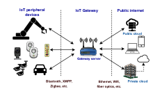
Apart from LW design, there is another subtle issue in incorporating cryptographic schemes into IoT devices. Consider a typical IoT ecosystem, as shown in Fig. 1. Here, the IoT peripheral devices connect to the public internet through an IoT gateway server. The IoT gateway architecture has several layers, such as a security layer, device layer, data management layer, etc. As part of connecting IoT peripheral devices, the IoT gateway servers perform data filtering and processing, protocol translation, authorization and authentication, etc. Whenever a user or device wants to connect to a peripheral device or vice-versa, the gateway servers have to run proper authentication and authorization protocols to make this happen. The gateway servers are usually powerful servers serving numerous IoT peripheral devices simultaneously. So, for them, high throughput is a more important operational metric than resource consumption. Meanwhile, the reverse is more important for IoT peripheral devices, which connect sporadically to the IoT gateway servers. Therefore, a flexible cryptographic scheme that can be instantiated either in a high latency and low resource consumption mode or in a low latency and high resource consumption mode is highly suitable in this scenario.
From a very broad perspective, this work aims to push the lower bound of the resource consumption of post-quantum cryptography, especially learning with errors (LWE)-based post-quantum cryptography. For the rest of this work, we will use the term lattice-based cryptography (LBC) to denote the cryptographic schemes based on the learning with errors (LWE) [Reg09] problem or its variants such as ring-learning with errors [LPR10], learning with rounding [BPR12], etc. We also want to delineate the term lightweight implementation here. For software implementation on resource constraint devices like Cortex-M0/M4 we use the term lightweight implementation for implementations with low memory footprint such as [BKS19, KBRV18, GKS20]. Lightweight design also implies low area and low-power or energy solutions for hardware devices such as field-programmable gate arrays (FPGA) or application-specific integrated circuits (ASIC); however, low-power or energy implementation cannot be demonstrated without custom ASIC design as FPGA defaults to high power-consuming interfaces. We expect that the ASIC version of our design will also reflect relatively lower memory as we can custom-make memory as per our requirement instead of using entire Block RAMs. We have demonstrated a low-area implementation on FPGA in this work. We have kept ASIC-related optimization as part of future work. Below, we briefly summarize the salient contributions of this work.
PQ KEM suitable for resource-constrained devices: We propose a lightweight post-quantum chosen-ciphertext attack (CCA) secure module-learning with errors-based key-encapsulation mechanism (MLWE-KEM), Rudraksh. In 1998, [HPS98] proposed NTRUEncrypt, a public-key encryption scheme that can achieve high speed and require low memory. Years later, [BGG+16] deliberated on a lightweight CPA-secure LWE-based key-exchange scheme suitable for IoT devices before us. However, none of these schemes are secure under chosen ciphertext attacks. Hermans et al. [HPVP11] have pointed out that a CPA-secure scheme can only provide security against a narrow range of adversaries. Therefore, in this work, we focus on designing a CCA-secure KEM. Kindly note that several CCA-secure NTRU-based KEM have been proposed during the NIST PQC standardization procedure. Most lattice-based KEMs, such as Kyber, Saber [BBD+21] (LightSaber), NewHope [ADPS16], and NTRU-based KEMs [CDH+19], have a low-security version design. Still, these are not explicitly designed to be lightweight, specifically for resource-constrained devices. One of the most prominent issues among the standardized PQC signatures is their large signature size compared to the classical signature schemes. This has a very detrimental effect on some protocols, such as transport layer security (TLS), where the increase in the size of certificates in the chain-of-trust model leads to serious performance degradation [SKD20] due to the congestion control mechanism of the transmission control protocol (TCP). To address such problems, NIST has called for another standardization [CML23] for PQ signatures with small signature sizes and fast verification time. In addition, some proposals have been made to replace the TLS handshake with a CCA-secure KEM, such as KEMTLS [SSW20] or TLS-PDK [SSW21], for better performance. Therefore, we believe that lightweight KEMs can profoundly impact the transition from classical PKC to PQC. Further, the techniques developed in this work can also be used to create a lightweight PQ digital signature scheme.
Practical design strategy: We adopt a new design style that is strongly coupled with hardware implementation. Our design decisions have been strongly driven by their potential advantage for lightweight hardware implementation. We explored the parameter space of LWE-based KEMs to propose optimum parameters that satisfy our design objectives. The NIST PQ standardization procedure witnessed a collective effort from researchers around the world for a thorough and rigorous analysis of different design elements of LBC. Therefore, to reap the benefits of the procedure and to bolster confidence in our designed KEM Rudraksh, we have kept the design very Kyber-esque. We refrained from making aggressive design decisions such as using non-constant-time modular reductions. We explore different centered binomial distributions with different variations for sampling error and secret vectors. However, we have not explored other distributions, such as the binary distribution [BGG+16] or the fixed weight distribution [BBF+19, CCHY23, PJP+22]. We also explored and analyzed different implementations of number theoretic transform (NTT)-based polynomial multiplication. We have used a modular reduction algorithm for lightweight hardware implementation. We also provided an optimized hardware implementation using the Xilinx Virtex-7 and Artix-7 FPGA to demonstrate the efficacy and justify our design decisions. We have also extensively compared our scheme with other state-of-the-art compact implementations of LBC.
Lightweight implementation: We demonstrated our design of Rudraksh using a lightweight implementation on FPGA. We observe that a major source of hardware overhead for lattice-based KEMs such as Kyber comes mainly from the bulky Keccak [BDPV13] module, storing the twiddle factors for NTT, and other memory requirements. We want to make this KEM design suitable for lightweight CCA-secure KEMs, so we focus on minimizing the area in terms of FPGA resources such as LUT, DSP, flip-flops, and memory with reasonable latency (54-81 s). ASCON [DEMS12] is a family of lightweight authenticated encryption and hashing algorithms. We have replaced Keccak with ASCON [DEMS12] to reduce the overhead of Keccak. This also demonstrates the efficiency and benefits of using ASCON in a LBC scheme. Our results show that area and memory can be reduced by approximately with respect to the most resource-optimized Kyber [HLLM24]. Our pipelined hardware implementation of Rudraksh can operate at 63%-76% higher frequency compared to high-throughput Kyber [DFA+20] and also provides time-area-product improvement compared to the compact implementation of Kyber [ZLZ+22].
2 Background and related works
We denote the set of integers modulo as and the quotient ring as (). The ring containing the vectors with elements and the matrix with elements from are represented as and , respectively. Lowercase letters indicate polynomials (), and bold lowercase letters denote vectors of polynomials (). Bold uppercase letters represent matrices of polynomials (). Multiplication of two polynomials and is denoted by . The number theoretic transform (NTT) representation of a polynomial is denoted by . The point-wise multiplication between these two polynomials in the NTT domain and is presented by . When NTT is applied to each constituent element of and , it is denoted as and respectively. represents vector-vector point-wise multiplication between vector of polynomials and vector of polynomials . denotes matrix-vector point-wise multiplication (PWM) between a matrix of polynomials and a vector of polynomials . represents that is sampled from the set according to the distribution , and we use to denote probabilistic output. indicates that is generated from the and follows the distribution , and we use to denote deterministic output. We use to denote uniform distribution and to denote the centered binomial distribution (CBD) with standard deviation . We denote the Hamming weight function by . denotes bit length of the bitstring .
2.1 Learning with Errors Problem
The learning with errors (LWE) problem was introduced by Regev [Reg09] and is as hard as standard worst-case lattice problems [Pei09]. Given , , and , where and are two narrow distributions. The LWE instance consists of the pair . The LWE problem states that for , it is hard to distinguish between the pairs and . The hardness depends on the distributions and the parameters . The Ring-LWE (RLWE) [LPR10] and the Module-LWE (MLWE) [LS15] problems are algebraically structured variants of the LWE problem. are polynomials sampled from the ring in the RLWE problem. In the MLWE problem, is a matrix of polynomials sampled uniformly from , and are vectors of polynomials sampled from the set .
2.2 MLWE-based Public-key Encryption
2.
3.
4.
5.
6.
return
2.
if is not specified then
3.
4.
5.
6.
7.
8.
9.
10.
11.
12.
return
2.
3.
4.
5.
6.
7.
return
A generic MLWE-based public-key encryption (PKE) is shown in Fig. 2. It consists of three algorithms: (i) key-generation (PKE.KeyGen) generates public-key and secret-key , (ii) encryption (PKE.Enc) takes the public-key and message as inputs and generates ciphertext , and (iii) decryption (PKE.Dec) takes inputs as ciphertext and secret-key and recovers the encrypted message. This PKE scheme is indistinguishable under chosen plaintext attacks (IND-CPA) based on the assumption of the hardness of the MLWE problem. Here, is a prime modulus, and are power-of-2 moduli. These algorithms use NTT to perform polynomial multiplication efficiently [LN16]. The function is defined as . is defined as . The is defined as and the is defined as . Compress, Decompress, Encode, and Decode operations are applied coefficient-wise to each polynomial and vector of polynomials.
2.3 MLWE-based Key Encapsulation Mechanism
2.
3.
)
4.
return
2.
3.
4.
5.
return
2.
3.
4.
5.
6.
7.
if then return
8.
else return
The PKE scheme described in Sec. 2.2 is IND-CPA. Indistinguishability under adaptive chosen ciphertext attack (IND-CCA) is a stronger security notion than IND-CPA and is desired to construct a KEM. The IND-CPA PKE in Fig. 2 is converted to IND-CCA KEM by applying a variant of Fujisaki–Okamoto (FO) transformation [HHK17]. As the PKE scheme is based on the MLWE problem, the PKE scheme is not perfectly correct (when the decryption of the encrypted message does not return the original message). If the underlying PKE is -correct, then the KEM based on the PKE is also -correct [HHK17]. Jiang et al. [JZC+18] proposed a IND-CCA KEM construction from a IND-CPA -correct PKE in the quantum random oracle model, and a slightly modified version of it is used in FrodoKEM [BCD+16]. The KEM shown in Fig. 3 closely follows the FrodoKEM construction. The IND-CCA MLWE-based KEM consists of three algorithms: (i) key-generation (KEM.KeyGen), (ii) encapsulation (KEM.Encaps), and (iii) decapsulation (KEM.Decaps). These algorithms use two hash functions, namely and . We also used two other functions. is defined by , where each of the coefficients of consists of bits of . If and , then repeat coefficients of consist of the same bit of . is the inverse function of . Therefore, . These two functions work as a repetition code with a majority vote when and random coin flip in case of ties. We discuss these in more detail in Sec. 3.1.
2.4 Related works
Most of the current lightweight PKC schemes are based on ECC [HB10, BMS+06, HWF08, BGK+06] which are not secure against quantum adversaries. Lattice-based constructions are promising candidates for designing lightweight PQC schemes. The NIST standard lattice-based KEM (e.g. Kyber [BDK+18]) or the finalists of NIST standardization (e.g. Saber [DKRV18]) are mainly designed keeping security and performance in mind. Afterward, LW implementations of these schemes have been proposed. For reference, Huang et al. [HHLW20], Xing and Li [XL21], Ni et al. [NKLO23] proposed optimized implementations of Kyber in various hardware platforms. Roy and Basso [RB20] presented an implementation of Saber on FPGA hardware, and Ghosh et al. [GBK+22, GBK+23] proposed an area and energy-optimized implementation of Saber in ASIC. There are several hardware or hardware/software co-designs of Kyber available [BSNK19, DFA+20, BUC19].
An RLWE-based encryption scheme with binary secrets and errors, called Ring-BinLWE, was proposed in [BGG+16] suitable for lightweight PKC applications. Subsequently, more efficient variants of this scheme have been published in the following works [LAM+22, XHW21, EBSMB19, HGX21]. However, these schemes are only IND-CPA secure and hence vulnerable to the chosen ciphertext attacks (CCA). Later on, Ebrahimi et al. [EBS20] proposed a CCA secure version of the IND-CPA Ring-BinLWE scheme, but the quantum bit security provided by this scheme is . This is relatively lower in comparison to Saber and Kyber, which provide at least 100-bit core-SVP PQ security even in their lowest security versions. There is always a trade-off between efficient implementation in the resource-constrained platform and security, and not much work has been devoted towards designing lightweight PQC without compromising security.
During the NIST PQC standardization procedure, a suite consisting of three learning with rounding (a variant of LWE problem) based PQC KEMs, Scabbard, was proposed in [BKKV21]. This work explored new design choices, such as a small polynomial size with for one of the schemes (Espada) to reduce the memory footprint of the implementation on the resource constraint Cortex-M4 device. Before that, the smallest polynomial size used in (R/M)LWE-based KEM was . In addition to this, several new designs of LWE-based KEMs, such as Smaug [CCHY23], TiGER [PJP+22], etc., have been submitted in the ongoing Korean PQC competition [Kpq]. Although the aforementioned works improved the state-of-the-art of LBC with different design choices and implementations, none of them explored all the possible design choices of LWE-based KEMs from the perspective of lightweight hardware implementations.
3 Rudraksh: Design Space Exploration
Designing a cryptographic scheme is fundamentally solving a multidimensional optimization problem where the primary objective functions are attaining a particular level of security, reducing latency and bandwidth (the size of the public key, ciphertext, and secret key). However, we impose new constraints on our lightweight design, such as low memory, low energy, and low area requirements to execute the scheme with reasonable latency. Our LBC design is influenced primarily by parameters, the structure of the module i.e the rank of the matrix and the size of the constituent polynomials , the prime modulus , and the standard deviation of the secret or error distribution. In this section, we discuss our design decisions and the rationale behind them in choosing these variables to achieve our design objective of a lightweight KEM.
3.1 Module space exploration
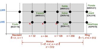
Keeping the and fixed, the security of the standard, module, or ideal lattice-based cryptographic scheme is dependent on the dimension of the underlying lattice only. Module lattices present a convenient and generic representation of different lattices; therefore, in this section, we will use the modules to describe different types of lattices. Let us consider a square module lattice111 in (M/R)LWE-based KEMs (or (M/R)LWR-based KEMs) is a square-matrix (i.e., number of rows = number of columns) to ensure the same security of key-generation (which uses ) and encapsulation (which uses ) as described in [LP11]. . The rank of the underlying lattice is . Upon fixing and , we get a standard lattice. On the other hand, if we fix and i.e. our lattice consists of a single polynomial, and we get an ideal lattice (RLWE). Indeed, for a long time before the proposal of module lattices [LS15], these two extremities were the only two choices available to design lattice-based cryptosystems, as shown in Fig. 4. Although Kyber [BDK+18], Saber [DKRV18], and Dilithium [DKL+18] are prominent examples of cryptographic schemes based on module lattices, a vast spectrum of lattice configurations with different values of or have been left unexplored. This is shown in Fig. 4 as a grey-shaded region. We explore this region to find optimal choices for and to design a lightweight KEM. It should be noted that this is not trivial. Intuitively, one might think that choosing a small would immediately lead to a lightweight design as it reduces the size of the multiplier. However, to maintain the for the security, decreasing increases . This implies more multiplications, more random numbers, larger moduli, etc. Similarly, just decreasing is also not useful for LW designs. We have to strike a delicate balance between and and other metrics that influence the scheme’s suitability for small resource-constrained devices. We discuss these different metrics and how they are affected by different values of and below.
Memory consumption: The matrix-vector multiplication is performed in PKE.KeyGen (therefore in KEM.KeyGen) and PKE.Enc (therefore in KEM.Encaps and KEM.Decaps) algorithm (shown in Fig. 2). The storage requirement for the public-matrix is one of the most memory-expensive operations for the LWE or LWR schemes that use module lattice structure. It requires storing polynomials of degree . Currently, the de-facto standard of lattice-based implementation is to generate this matrix using the just-in-time [KBRV18] strategy. This method generates the matrix one polynomial at a time by utilizing the sponge-based periodic ‘..squeeze-absorb-squeeze..’ operation of the extended output function (XOF) such as Keccak [BDPV13]. Therefore, the memory requirement to perform the matrix-vector multiplication is proportional to the size of one single polynomial. As we move towards the left of Fig. 4, polynomial size decreases. So, although has to be increased to maintain the security level, the memory requirement in this configuration is smaller. We store a single polynomial for all the polynomial multiplications in hardware platforms. Of course, one can take extreme measures such as generating a single coefficient at a time and performing a single integer multiplication to reduce memory. However, it would drastically deteriorate performance.
In the MLWR-based schemes, the error vectors are generated implicitly. This implies that we do not need to invoke the XOF (or the CBD) module to generate the error vectors in the MLWR-based schemes. Nevertheless, we need to invoke these modules to generate secret vectors in both MLWR and MLWE-based schemes. Therefore, we need these modules on the hardware in either of these schemes. Hence, the implicit generation of error vectors in MLWR-based schemes offers no advantage from area-optimization point-of-view. Also, for the rounding operation, in MLWR-based schemes such as Saber [DKRV18], the modulus and the rounding modulus are chosen as power-of-two numbers. Due to this, MLWR-based KEMs use Toom-Cook-based polynomial multiplication, which generally consumes a relatively larger area/power/latency than NTT-based multiplication used in MLWE-based schemes [KNK+24]. In MLWE-based KEMs that support NTT natively, can be sampled directly from the NTT domain instead of first sampling and then performing NTT() to generate . However, one can also perform the evaluation stage of Toom-Cook multiplication (evaluation-schoolbook multiplication-interpolation) and store it [BKV20, KRS19]. However, it is not in-place like NTT and requires more memory than the original . Although following the work of Chung et al. [CHK+21], an NTT can be used for MLWR-based schemes by choosing a large NTT-friendly prime that envelopes the modulus and growth of error during multiplications. This strategy helps MLWR-based schemes, such as Saber, achieve performance comparable to Kyber on the ARM Cortex-M4 platform. However, the area requirement (or the stack memory of Cortex-M4 implementations [ACC+21]) increases significantly for MLWR-based KEMs due to their larger modulus. Recently, three MLWR-based KEMs have been proposed in [BKKV21] and their hardware implementation in [KNK+24]. This work shows that Toom-Cook-based polynomial multiplication can be made resource-constrained at the cost of more cycles. Therefore, we explore possible MLWE schemes with smaller polynomial sizes, which can be implemented with low resources without much performance degradation. We primarily target schemes where is power-of-2 and less than , such that , , and .
Multiplier size: In the case of a standard lattice-based scheme with matrix rank , one of the most computation-heavy operations is multiplications between matrix and length vector. For the ring lattice-based scheme, we have to perform polynomial multiplications between two degree polynomials to achieve a similar level of security. This can be done using quasi-linear NTT multiplication. Hence, for a particular security level, the ring lattice-based schemes are more efficient than the standard lattice-based schemes in terms of computational cost. However, the resource consumption in that case is relatively huge as two degree polynomials must be stored to perform the polynomial multiplication. Therefore, for a specific security level, due to the just-in-time strategy, the module lattice-based schemes are more beneficial in reducing resource consumption than the ring lattice-based schemes. Although we have to perform multiple polynomial multiplications due to the use of module structure, module lattice-based schemes perform better than the standard lattice-based schemes. The choice of the hard problem i.e. MLWE or MLWR, and polynomial size determines the size of the multiplier in hardware. Nevertheless, the resource consumption is proportional to the size of a single polynomial for module lattice-based schemes. Therefore, choosing the hard problem and polynomial size is one of the leading factors when designing an efficient scheme for resource-constrained devices. Generally, the size of the polynomial is chosen in multiple with the size of the secret message () bit-length [ADPS16, BDK+18, CKLS18]. If , , and for an integer , we use repeat coefficients of ciphertext polynomial (generated during the encryption algorithm shown in Fig. 2) to hide a single message bit of by replicating a single message-bit repeat times using function. Please note that we use of the message bits only when , otherwise . We now discuss the process of calculating failure probability when the repeat is greater than 1. For example, if repeat=3, the failure happens when at least two of the three message bits are decoded to the wrong value. Then the new failure probability is calculated as , where is the failure probability when repeat=1 (no repetition). If repeat=4, the failure occurs when at least three of the four message bits are decoded to the wrong value. Failure also occurs when two of the four message bits are wrong with half probability (as in this case, one of the two choices would be chosen randomly, which can be correct with only half probability). Then the new failure probability is calculated as . This calculation changes depending on repeat. However, we would like to mention that a designer can choose various approaches to encode message bits into the ciphertext polynomial when . Unlike the error correcting code used in LAC [LLZ+18] where timing attack has been shown in [DGJ+19], the (and also ) function can be implemented in a constant-time manner. Now, if the polynomial-size is smaller than the size of the message bit-length i.e. for an integer . In that case, we have to encode message bits into a single coefficient of ciphertext polynomial [BCD+16] as displayed in Fig. 2. This would increase the requirement of the reconciliation bits () and eventually the modulus of a coefficient of (). This will require a larger modulus , which reduces the security. We will discuss this phenomenon in more detail in Sec. 3.2.
Flexible design: Module lattices present an opportunity to design cryptographic schemes that benefit the IoT architecture as discussed in Sec. 1. The structure of module lattices can be utilized to instantiate such a flexible scheme. Let us assume a cryptographic scheme uses a module lattice of size . An extremely low latency and high resource-consuming implementation can be realized by implementing multipliers in parallel, and an extremely lightweight and high latency version can be realized by implementing a single multiplier repeatedly using for times. Here, of course, the XOF has to be implemented accordingly to match the latency of the multiplier. As discussed before, polynomial arithmetic, specifically polynomial multiplication, is one of the major bottlenecks in LBC’s performance and resource consumption. The polynomial size in both Kyber and Dilithium is . Even in the most lightweight instantiation, an IoT peripheral device has to use a polynomial multiplier (more specifically, NTT multiplication, which includes size- NTT, size- INTT and size- point-wise multiplication). This is still very expensive for an IoT peripheral device. A smaller polynomial size is more suitable with some sacrifice in efficiency. Therefore, a balance has to be struck between these two metrics for a suitable lattice-based PQ scheme for IoT.
In conclusion, ring lattice-based schemes are especially advantageous for achieving better performance, but they require more hardware area. Meanwhile, standard lattice-based schemes theoretically can be implemented with lesser memory and area at the expense of substantial computation costs. Module lattice-based schemes with polynomial-size and underlying lattice’s matrix rank provide a trade-off between them. If we keep constant, and increase then decreases proportionately, which reduces the memory requirements for a single polynomial. However, this increases the generation cost of the matrix , as the matrix consists of pseudo-random bits. These pseudo-random numbers are generated by using an XOF, which is another computationally expensive operation as described later in Sec. 3.5. If memory is not a concern, then increments of can be used to increase parallelism in hardware implementations. There are some module LWR-based designs that have been proposed in recent years [DKRV18, BKKV21]. However, the module-space for designing different MLWE-based schemes remained mostly unexplored. Therefore, we choose to explore the module space for the LWE problem denoted by red colored stars in Fig. 4 to construct a lightweight MLWE-based KEM with optimal parameters.
3.2 Choice of moduli
It is clear from the discussion in the previous section that we want to explore the module lattice space to design LW lattice-based KEM. LWE-based schemes use reconciliation mechanisms by sending some extra bits [BDK+18] ( in Fig. 2). These bits help to recover the encrypted message during the decryption algorithm by reducing the noise introduced during the encryption procedure called decryption noise (as LWE-based encryption schemes are not perfect). Increased decryption noise induces an increment in the failure probability, which can cause a decryption failure attack [DGJ+19]. As discussed earlier, a smaller polynomial size reduces the memory consumed by a single polynomial and also the area required to implement single polynomial multiplication in hardware. But, if we reduce the size of the polynomial , then we have to encode multiple message bits in a coefficient of . This will increase the failure probability. This can be compensated by more reconciliation bits i.e., larger , which in turn increases and the ciphertext size.
The security of a lattice-based cryptosystem increases with the increase in the error-to-modulus ratio, i.e. keeping the error distribution fixed, the security will reduce with the increase in the value of , and vice versa. Therefore, a smaller value of helps to increase efficiency, reduce computational and storage resources, and also reduce the bandwidth (size of the public-key, secret-key, and ciphertext), but increases the failure probability. Hence, we concentrated on finding an optimal value of the modulus for which the decryption failure would be minimal. We also proposed implementations with minimal hardware resources. The type of the modulus i.e prime vs. power-of- modulus also has a significant impact on the performance and resource utilization of the scheme. We have deferred this discussion till Sec. 3.3.
3.3 Choice of polynomial multiplication
For LBC schemes, polynomial multiplication is one of the major bottlenecks with respect to efficiency and resource consumption. In literature, there exist mainly two types of polynomial multiplication algorithms for implementing LBC schemes: i) Toom-Cook multiplication [Too63, Coo66], and (ii) NTT multiplication [Pol71, LN16]. Toom-Cook multiplication is relatively simpler and can be used for any modulus. However, the time complexity of the Toom-Cook polynomial multiplication is asymptotically slower , where . On the other hand, NTT multiplication is the most used polynomial multiplication for implementing LBC schemes due to its faster quasi-linear time complexity (). However, for the NTT multiplication, the modulus needs to be NTT friendly i.e. a prime number with the primitive -th root-of-unity in the prime field . Please note that, for small values of , the efficiency of Toom-Cook polynomial multiplication with a power-of- modulus (as modular reduction is free in a power-of- ring) and NTT-based polynomial multiplication on an appropriate prime modulus is comparable when performed the full multiplication. However, for LBC schemes, we can sample the public matrix from using instead of sampling and performing NTT on . It can save cycles while computing as is random implies is random and vice-versa. We also can save execution time on the NTT-based polynomial multiplication by omitting the INTT operation and keeping the multiplication result in the NTT domain (e.g., Line (5) in the PKE.KeyGen() in Fig. 2). This makes the LBC scheme with NTT multiplication more efficient than Toom-Cook multiplication. Therefore, we choose to use NTT-based polynomial multiplication over a prime modulus .
NTT multiplication between two polynomials and from is performed by . Given is the -th primitive root of unity and , the and are denoted by the following Eq. 1 & 2.
| (1) | ||||
| (2) |
In this procedure of multiplication, we have to store the pre-computed values of (for ) along with the coefficients of two participated polynomials for improving the performance. Therefore, the total memory requirement to perform multiplication depends on polynomial size .
In the literature, there is another type of NTT called incomplete NTT multiplication, where the NTT multiplication between two size polynomials is replaced by two separate NTT multiplications between two size polynomials. Karatsuba multiplication is performed on the last -degree polynomials. Therefore, incomplete NTT multiplication requires more modular multiplications than complete NTT multiplication. Yet, the incomplete NTT multiplications outperform complete NTT multiplications [AABCG20] on software by omitting several reduction steps after modular multiplication. Incomplete NTT multiplication is also used in Kyber. We employ a single butterfly module shown in Fig. 8 that includes a reduction step for performing NTT, INTT, and PWM in our KEM. Therefore, incomplete NTT multiplication increases the latency in our KEM implementation. Consequently, we choose the complete NTT multiplication over the incomplete one for polynomial multiplication. More details regarding NTT multiplication are provided in Sec 4.2.
3.4 Secret and error distribution
In LWE-based schemes, coefficients of secret and error are usually sampled from a narrow distribution. There are several (M/R)LWE-based KEMs that have utilized discrete Gaussian distribution as secret and error distribution [BCD+16]. Unfortunately, it is hard to implement a Gaussian sampler efficiently and securely against timing attacks. For KEMs, Alkim et al. [ADPS16] showed that this Gaussian distribution can be replaced with a centered binomial distribution (CBD) whose standard deviation is the same as the Gaussian distribution. The sampling from a CBD is much simpler and easier to protect against side-channel attacks. Several other distributions have been explored in the design of LWE-based schemes to gain efficiency, such as binary distribution [BGG+16], fixed weight distribution [BBF+19, CCHY23, PJP+22], etc. However, as our goal was to design a Kyber-esque scheme, we had limited our search space to CBDs () with different . The above-mentioned other distributions can also be potentially used as secret and error distributions for lightweight cryptography, but we have not investigated them in this work.
The parameter impacts the security parameters of a CCA secure scheme, failure probability, and bit security. The standard deviation of is . Suppose the modulus and the rank of the lattice are fixed. In that case, both the bit security and the failure probability of the scheme increase as the standard deviation (for CBD, ) increases. The sampling from a CBD is accomplished by performing , where are bit pseudo-random numbers. The parameter of CBD is crucial in deciding the scheme’s efficiency. The CBD sampler uses pseudo-random numbers, and the bigger the CBD parameter , the more pseudo-random numbers generation will be required. Pseudo-random numbers are generated using some extendable-output function (XOF). The XOF is one of the costliest operations in terms of computation and resources (Details about XOF have been provided in the next subsection). Finding a smaller is necessary for better performance, less resource utilization, and lower failure probability. However, a larger increases the bit security. As we are aiming for a CCA-secure KEM scheme with -bit Core-SVP PQ security using FO transform [HHK17], the failure probability must be .
Hence, in our design, we have analyzed these aspects with a wide range of values of to find an optimal choice to strike a balance between the security and efficiency of our scheme.
3.5 ASCON based hash and XOF functions
The implementations of LBC exhibit a unique and interesting phenomenon. Lattice-based cryptographic schemes use a lot of pseudorandom numbers to generate the matrix and the secret and error vectors. From a designer’s perspective, generating pseudorandom numbers is considered an auxiliary function that does not impose major overhead on executing the whole scheme. More focus is given to optimizing the core functions of the cryptographic scheme as they consume the majority of the time and resources in various implementations. This is true for classical PKC (and symmetric-key ciphers also) schemes such as RSA [RSA78] and ECC [Mil85], where most of the time and resources are spent on making the multi-precision multiplications and scalar point multiplication, respectively. However, for LBC, the standard approach of generating pseudorandom numbers is using an XOF such as Keccak [BDPV13]. This process takes close to or, in some cases, more than of total time and/or area [XL21]. As numerous works have been done to optimize the core operation of LBC, which is polynomial multiplication in software and hardware platforms [RB20, BTK+20], the process of random number generation has become the bottleneck.
To alleviate this problem, designers have proposed alternative versions of their schemes, such as Kyber-90s [ABD+21] or Saber-90s [BBD+21] where they proposed to generate the random numbers using a block cipher (such as AES [Can05]) in counter mode. While this could be a good solution for software and hardware platforms with dedicated support for these block ciphers, such as the AES-NI instruction set, for standalone hardware with minimal software support, this is not a good solution. As shown in Fig. 3 (for ), we need to use secure hash functions for a CCA-secure KEM using the FO transformation. Therefore, we cannot completely remove the Keccak module from the hardware platform. Moreover, we must include another module implementing the block cipher algorithm. Another strategy for reducing the overhead of Keccak could be using round-reduced Keccak [BDH+23] to generate , , and (, , ), where only uniform randomness is needed [pqc24]. However, there is not enough research to engender enough confidence to use the round-reduced Keccak as a reliable pseudo-random number generator. Therefore, more research is required to determine the security versus efficiency trade-off. Moreover, we wanted to use a standard hash/XOF function, which went through several security analyses in our scheme.
Therefore, the best possible solution in this scenario is to replace the bulky Keccak module with some lightweight alternative. NIST concluded its lightweight cryptography competition [NIS23a] in February 2023 and selected the ASCON [DEMS12] family of lightweight ciphers. Like Keccak, ASCON is also based on the sponge construction [BDPV11] and can be used as a Hash function and XOF. Moreover, ASCON is specifically designed for lightweight implementation on resource-constrained devices. This makes ASCON an ideal choice for replacing the Keccak function in our design. However, this is not very straightforward. The biggest hurdle is the difference in the state size of these two ciphers, which are and bits for ASCON and Keccak, respectively. Therefore, each ASCON-squeeze outputs a fraction of pseudorandom bits compared to a Keccak-squeeze. Hence, to utilize ASCON’s full potential, we have carefully designed our architecture exploiting the lightweight sub-layer and linear layer of ASCON, as well as meticulous scheduling and memory organization in the FPGA implementation such that the smaller throughput does not become the operational bottleneck (explained in Sec. 4.3). Another hurdle in replacing Keccak with ASCON is that the current version of ASCON provides maximum 128-bit security; therefore, it is unsuitable to replace SHAKE-256 or SHA3-512, which has been used in Kyber for higher security versions. However, it is fine for our lightweight design. Due to these issues, replacing Keccak with ASCON and achieving efficiency is not straightforward.
3.6 Parameters of our scheme
| Module Parameter | Primary modulus | Compression modulus | CBD parameter | Encoding | Bit-security | ||||||
|---|---|---|---|---|---|---|---|---|---|---|---|
| Scheme name | (Quantum, Classical) | Failure probability | |||||||||
| KEM-poly32 | 21 | 32 | 31873 | 15 | 12 | 3 | 2 | 2 | 4 | (105, 116) | -113 |
| KEM-poly64 | 9 | 64 | 7681 | 13 | 10 | 3 | 2 | 2 | 2 | (104, 114) | -128 |
| KEM-poly128 | 4 | 128 | 3329 | 12 | 10 | 2 | 2 | 2 | 1 | (101, 111) | -179 |
| Kyber [ABD+21] | 2 | 256 | 3329 | 12 | 10 | 3 | 3 | 2 | 1 | (107, 118) | -139 |
| NewHope [ADPS16] | 1 | 512 | 12289 | 14 | 14 | 2 | 4 | 4 | 1 | (101, 112) | -213 |
We target to attain at least -bit post-quantum core-SVP security for our lightweight KEM. It will provide equivalent security with AES- [AAC+22] and belong to the NIST-level-1 security category. Therefore, the current version of ASCON with bit security is enough for us. In this section, we discuss the process of finding parameters for Rudraksh.
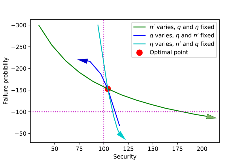
Leaky-LWE estimator [DSDGR20] is the state-of-the-art tool to estimate the hardness of the underlying LWE problem. It uses the best-known lattice reduction algorithm Block Korkine-Zolotarev (BKZ) [SE94, CN11] algorithm. BKZ algorithm primarily estimates the difficulty of solving the shortest vector problem (SVP) in a smaller lattice. This is known as core-SVP hardness. The security of the overall LBC scheme is the hardness of this core-SVP problem with some polynomial overhead. Usually, we ignore this polynomial overhead for a pessimistic estimate of security. The leaky-LWE estimator tool takes the underlying base matrix rank , the modulus , and the standard deviation of secret or error distributions of a scheme as input. It returns both post-quantum and classical bit security of the corresponding scheme. As discussed earlier, while designing a module lattice-based scheme for resource-constrained devices, the two most important parameters are the polynomial-size and the length of the vector . We have viewed finding the optimal parameter set for our lightweight KEM as a multi-dimensional optimization problem. First, we fixed the polynomial-size and exhaustively searched all the possible values of other parameters such as the vector length , modulus , and CBD parameter , , etc. This is followed by calculating the resource consumption for these parameters. We have repeated the process for all the power-of- polynomial sizes to maintain the efficiency of the scheme as it is beneficial for the implementation of several primary building blocks, such as NTT multiplication, , functions, etc. We also did not explore the polynomial-size below , as the failure probability increases in these cases drastically. We have to increase the modulus a lot to counteract the high failure probability, affecting the scheme’s efficiency. To attain the targeted security, we have to increase the length of vectors, which will also affect the scheme’s efficiency. We provide optimal parameter sets for three configurations (i) KEM-poly32: with polynomial-size , (ii) KEM-poly64: with polynomial-size , (iii) KEM-poly128: with polynomial-size . The parameters of all these configurations are shown in Tab. 1. This table also includes the parameters of Kyber [ABD+21], where the , and NewHope [ADPS16], where . We also provide the process to find parameters for KEM-poly64 in Fig. 6. To calculate the failure probabilities, we followed the exhaustive search strategy similar to other LWE-based schemes, such as Kyber, Saber, NewHope, etc. While exploring the KEMs of this work, i.e., KEM-poly32, KEM-poly64, and KEM-poly128, we keep repeat=1 (as ).
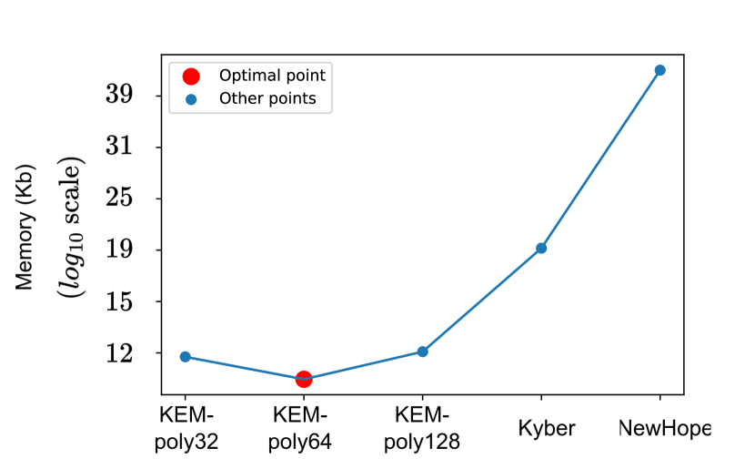
Memory and area are two primary benchmarks for hardware resource consumption. The memory possesses all the resources used for data usage, which includes all the on-chip memory structures such as Block-RAM (BRAM), distributed RAM, etc. The area contains the configuration logic resources, including look-up tables (LUTs) and logical elements. Now, we discuss the estimated hardware resource usage of all the schemes presented in Tab. 1 in terms of memory and select the one that can be operated with optimal resources. Each polynomial of the secret-key vector can be generated from . These secret polynomials generate the public-key vector during the key-generation procedure or used in the PKE.Dec (Fig 2, line (3) in PKE.KeyGen) during the decapsulation algorithm. One polynomial length ( bits) memory storage is required for the secret polynomial (for in PKE.KeyGen, for in PKE.Enc), and for the runtime calculation of single polynomial in the public matrix . For efficient implementation, another polynomial storage is required for the roots of unity (or twiddle factors). We use one more polynomial space to save the ciphertext as well as a vector of polynomial space ( bits) to store the public vector in the key-generation algorithm, and that same space is used to store the ciphertext vector during PKE.Enc. We also need -bit ASCON state register for KEM-poly32, KEM-poly64, KEM-poly128, and -bit state register of Keccak for Kyber and NewHope. Extra buffer is often used for post-processing for hash (for in encapsulation and , in decapsulation) and the pseudorandom number generated during key generation and used in decapsulation algorithm (for the cases of decryption failure). This buffer size is equivalent to the state register. Therefore, we need memory for four polynomials, one vector of polynomials, states of ASCON or Keccak, and storage for hash output and . We calculate the storage requirement for each of the configurations of Tab. 1 and present them with the help of Fig. 6. It is evident from Fig. 6 that KEM-poly64 uses the least storage compared to other configurations. Therefore, we select KEM-poly64 as our lightweight KEM Rudraksh and present a lightweight (low-resource) hardware implementation. The public-key, secret-key, and ciphertext sizes of Rudraksh are 952, 1920, and 760 bytes, respectively. These sizes are equivalent to/slightly higher than those of Kyber, which are 800, 1632, and 768 bytes. This is mainly due to our design decisions and prioritizing resource requirements over communication bandwidth requirements. Usually, lightweight devices use protocols such as BLE and ZigBee for data transmission, which are extremely power- and energy-efficient. Regarding the energy consumption for data transmission, our scheme is similar to that of Kyber. Moreover, our design uses a smaller polynomial size, and the encapsulation/decapsulation module of Rudraksh can start its computation after receiving a public-key/ciphertext polynomial. Hence, we can transfer the key/ciphertext one polynomial at a time without affecting the scheme’s efficiency. Although this process does not reduce the total number of byte transfers via a network, because of this interleaved operation between communication and computation, our scheme can operate with a smaller bandwidth. Such techniques need to be explored further in the real-world environment.
4 Hardware design
After exploring the theoretical design decisions for developing a lightweight lattice-based KEM, we efficiently implement the scheme and show the scheme’s area and latency requirements in hardware. We have chosen Xilinx Virtex-7 and Artix-7 FPGAs as our target devices. Our hardware design consists of several components. First, we discuss the system architecture; second, we discuss the re-configurable butterfly architecture; and finally, we discuss the datapath of the ASCON-based XOF function. We also discuss the other computational units, such as the CBD sampler, rejection sampling unit, etc. We also discuss our efficient memory organization, as careful memory organization is crucial for memory reduction. Note that reducing memory is important for lightweight design as most use cases are memory-constrained IoT devices. They will often share the memory with other systems, and careful memory-reduced design is of utmost importance. Efficient NTT memory access removes the need to reorganize memory, which increases latency overhead. Finally, we describe the scheduling during all the operations.
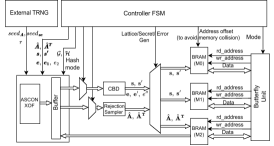
4.1 System architecture
The full system architecture is shown in Fig. 8. The seeds of matrix , secret , and error are taken from an external True Random Number Generator for demonstration. A controller FSM controls ASCON-XOF and butterfly units synchronously. It enables/gates the CBD/rejection sampler when not required. For example, sampling does not require CBD and hence is gated by the controller. The controller also provides an address offset to avoid memory collision with the public/secret key if we want to store them. The ASCON permutation is used for the , and functions. It is the key function to generate the public matrix of polynomials . Each coefficient of the polynomials is bits and less than the prime modulus . Therefore, an additional rejection sampler is needed to discard coefficients , while generating . The ASCON core is also used to generate the pseudo-random number for the CBD sampler module to construct the secret (or ). The secret is directly stored in 2 NTT memories. The reconfigurable butterfly unit performs the NTT/INTT/point-wise multiplication(PWM) operation. Synchronous memory access for NTT and INTT are ensured in the design. We discuss the details in Sec. 4.4. PWM is a vector multiplication. Since the polynomial-size is small (), we use complete NTT multiplication, unlike Kyber, where PWM is complex, as it uses incomplete NTT multiplication along with Karatsuba multiplication in the last step as part of PWM.
4.2 Reconfigurable butterfly unit
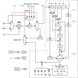
We introduce a reconfigurable butterfly unit for NTT, INTT, PWM, compress, decompress, encode, and decode functions. The butterfly unit is configured by the 3-bit mode signal provided by the controller (Fig. 8). A single DSP unit is used for multiplication. Notably, multiplication is a key operation in all the previous computations and takes a significant area. The DSP unit performs the multiplication between the twiddle factor ( where ) and in NTT/INTT operations. We adapted Zhang et al.’s [ZYC+20] technique for INTT. Here, the multiplication with of Eq. 2 is replaced by the in each butterfly operation. This step eliminated complex multiplication by 1-bit left shift operation at negligible hardware cost. The butterfly unit also consists of an adder/subtractor, as shown in Fig. 8. Finally, it includes a three-stage pipelined shift-and-add modular reduction, ensuring a very low critical path for the design. It is important to note that ASCON-XOF is extremely lightweight, and its substitution layer consists of a few ’xor’ and ’and’ gates. Hence, we use 6-stage pipelines in the butterfly to maintain a low critical path, resulting in a high-frequency design.
Only the multiplication and the modular reduction are enabled, while the butterfly operates in PWM mode. We employ the butterfly unit to compute , defined by followed by keeping the lower 10 bits (similar to [ABD+20]). The division by is replaced by multiplication with an approximate value of . This procedure includes multiplication with followed by bit right shift. We use a similar technique to compute . Here, we substitute the division by with multiplication with followed by bit right shift. While computing , we replace the division by with multiplication with and followed by bit right shift. , , and involve a multiplication with . All the right shift operations are implemented using a configurable barrel shifter. We describe modular reduction hardware in detail below.
Modular reduction: Modular reduction is one of the crucial parts of the butterfly core. Some of the primarily utilized modular reduction algorithms are Montgomery reduction [BDK+18] and Barrett reduction [XL21]. However, it is important to note that while using Montgomery and Barrett reduction following [ABD+21], one extra multiplication followed by the reduction converts a polynomial to the Montgomery domain. Returning from the Montogomery domain often requires one extra multiplication, costing extra latency for an extra DSP unit. Later, for primes like , where is an odd number, the -reduction [LN16] algorithm has been proposed. This reduction algorithm performs better and consumes less area on hardware than the Montgomery or Barrett reduction. Subsequently, the -reduction algorithm is introduced by Bisheh-Niasar et al. [BAK21], which is more efficient than the -reduction algorithm. -reduction algorithm takes input and outputs , and -reduction algorithm takes input and outputs . We can eliminate the extra , , by replacing the pre-computed factor by during NTT or INTT. However, while using the -reduction during point-wise multiplication, we have to perform one extra multiplication followed by the reduction to discard the extra factor. It either increases the number of DSPs (containing one multiplication unit) or the latency. However, this extra step is unnecessary if we use the shift-and-add modular reduction technique. We used this technique for our prime and presented it in Alg. 1. It is an improved lightweight hardware-assisted variant of -reduction. The detailed implementation is shown on the right side of the butterfly unit (Fig. 4.2). The modular reduction only needs addition/subtraction and bit shift operation, making it extremely lightweight and suitable for high-frequency operations.
4.3 ASCON core as XOF function
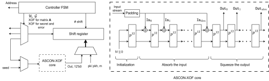
ASCON-XOF takes an input of arbitrary size in chunks of 64 bits and generates an output with variable lengths (in chunks of 64 bits). ASCON is also a sponge-based construction like Keccak. It offers a smaller state size of bits (64-bit rate and 256-bit capacity), whereas the Keccak state register size is bits. ASCON-XOF can be implemented with low-area (Fig. 9). It supports several functional modes which are to generate the public-matrix , the CBD sampler to generate the secret (or ), error (or ), and . The global controller fixes the mode for this block.
ASCON-XOF function has three steps: a) initialization, b) absorb, and c) squeeze. The initial state register is pre-computed from in our design to save latency. The second step is to absorb the input stream in the block of bits. In Fig. 9, denotes . During absorb, bits input block is XORed with the first bits of the state register followed by . The third step is to squeeze the output bits. This process continues until the required length of output is extracted. We denote by in the figure. ASCON permutation is the primary building block of the ASCON-XOF function. It is used during all the three steps. This permutation consists of three steps: (i) addition of constant round, (ii) substitution layer, and (iii) linear diffusion layer [DEMS12].
The rate of input and output block of ASCON is only -bit. ASCON’s permutation includes only bit-wise XOR, circular shift, and bit-wise AND operations. Therefore, single permutation takes considerably less number of gates than Keccak. Moreover, this implies that the critical path of the ASCON permutation is small and, hence, increases the maximum frequency. The execution of the ASCON permutation at a higher frequency compensates for high clock cycle consumption during absorb and squeeze functions. It helps this design compute with a similar order of latency as Kyber. This design decision assists in attaining an efficient performance with reduced area usage and makes it especially suitable for lightweight designs.
This ASCON-XOF hardware also contains a -bit buffer/shift register. This buffer stores the input of the absorb while computing . Each coefficient of the vector of polynomials is bits, and we save the in coefficient format one by one. Once a minimum of 64 bits is stored, those bits are used for absorption while new coefficients are introduced in the buffer. The ASCON absorb’s input block size is bits (determined by ASCON rate). We load the first coefficients of ( bits) to the shift register for the first absorb. The input block of the first absorb step consists of the first coefficients and bits from the least significant bits (LSB) of the th coefficient. One bit of the th coefficient remains in the shift register. Then, we load the next coefficients of the to the shift register. Now, the shift register holds bits of input. We use bits from the LSB (including the remaining bit of the 1st coefficients) as the second input block. This process continues until the whole is absorbed. As the greatest common divisor between and is , the minimum size of the shift register needs to be to accommodate extra bits of the input stream for all possible cases.
The same buffer temporarily stores the output blocks when the ASCON block works in PRF mode, producing the public matrix . ASCON squeeze generates -bit output after a round permutation , and each coefficient size of is bits. Then, these coefficients are fed to the rejection sampler. It accepts if the coefficients are less than . So, only four coefficients can be constructed after a single squeeze. There will be bits remaining in the shift register. After the next squeeze, another bits output is added to the shift register. To accommodate all the bits, the same -bit shift register is used. From these bits, bits from the LSB are utilized to construct the next coefficients of the matrix , and bits will remain in the shift register. This process will continue until the whole matrix is generated.
The ASCON block is required to sample the secret (or ) and error (or ). The pseudorandom bits created by ASCON permutation are fed to the CBD sampler to construct the final secret and error coefficients. Here, the bytes seed + byte nonce222The nonce is specific to each of the polynomials, and its value depends on its index. For example, this extra byte for is , for is , for is , and for is . Two extra bytes are used to generate the polynomial of matrix ; one indicates the column number, and the other is the row number. This method helps to reduce bookkeeping hazards and reduce memory consumption. works as the input of the absorb step. Three absorb steps are required as the input block size is bits. To construct a coefficient of the secret or error, bits of XOF output are needed. Therefore, -times squeeze is required to generate a single polynomial.
4.4 Memory organization
One of the key design aspects of our design is to reduce memory as much as possible to make it resource-constraint-device friendly. We took two key approaches to achieve this. First, we reduce total memory by carefully choosing the generation of lattice and secret . Second, NTT memory organization is done carefully to accommodate the minimum BRAM usage for NTT.
We use just two 18K BRAMs for NTT/INTT operations and one 18K BRAM for run-time lattice generation and public key storage. While we generate , the careful design choice of 64-point polynomials gives us the perfect opportunity to synchronize ASCON-XOF-Based generation and operation. For example, generation of ( bit) consumes 192 (= for absorb + for squeeze) cycles. However, we often need to squeeze more to accommodate more coefficients, as some are rejected. This takes 12-24 cycles more on average. Our NTT is a single butterfly design; hence, takes = 192 cycles. This careful design ensures that both hardware components work synchronously. This also gives us the perfect opportunity for a runtime secret generation, which may not be preferred for NIST standard Kyber as NTT takes significantly more cycles for Kyber. As we need to generate lattice , can be done within that time. This ensures that we can store the secret seeds and generate them every time, reducing the memory requirement for the secret by a significant amount. For example, we need to keep storage of 1 polynomial generation related to the secret generation contrary to 1 vector of a polynomial of the most optimized Kyber design [NIS23b]. If we choose 128-/256-point NTT, takes more cycles, causing run time secret generation to be infeasible. We also use trivial ML-KEM optimization [NIS23b], such as run-time generation. We have a separate memory for the public key. However, that is not necessary if it is integrated with IoT devices. IoT devices often have extra memory, which can be utilized to communicate with another party.
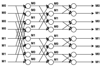
NTT memory is implemented with 2 separate memory as shown in Fig. 10. Once the secret is generated, 1st half is written in one BRAM, say M0, whereas 2nd half is written in M1 as coeff[0], and coeff[32] is required in the first stage. At every level, writing is swapped to ensure the next stage data is available from 2 different memory. This strategy ensures streamlined dataflow even with a single port write-enabled memory. We are using 3, 18K BRAMs for this implementation. However, total memory is not used. For example, M0 & M1 need just -bit memory each (416 bit, 2.3% of 18K memory).
4.5 Scheduling
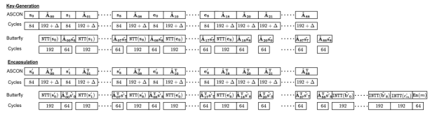
Scheduling is an important aspect of KEM hardware design. There are two parallel components of the KEM data path: (i) butterfly unit, which computes NTT, INTT, and PWM as well as encode, compress, and decompress, and (ii) Hash/PRF functions (ASCON-XOF for our case, SHA3 and SHAKE for Kyber). These two components are independent. This allows us to schedule synchronously, as shown in Fig. 11. Note that both components are specially required for the keygen and encrypt phases. Decrypt only needs butterfly, whereas FO-related functions require ASCON-XOF only. We sample using ASCON-XOF and CBD, which needs 84 cycles; then, one polynomial is sampled using rejection sampling followed by ASCON XOF. It is important to note that rejection sampling, in this case, takes at least 192 cycles, which is enough to calculate 64-point NTT. Then, while sampling the next secret, we can multiply and accumulate it as that takes fewer cycles. A lightweight ASCON core takes multiple cycles to create the matrix or , even if the secret is stored. We have the option to store the entire secret in memory. However, runtime generation of the secret polynomial costs only 160 cycles of latency in the key generation/encryption function, which is negligible. As we are targeting lightweight design for energy and area-constrained IoT devices, we have taken this approach to reduce memory further.
4.6 Other computational units
We require two more components: rejection sampling and CBD sampler. Rejection sampling is a part of matrix or generation. It checks and accepts if the ASCON-XOF generated bits output is less than . Otherwise, it rejects those bits and proceeds with the next bits. The implementation of this component is not constant time. However, it does not affect the security as the matrix is a public matrix. The CBD sampler is used to sample coefficients of the secret polynomials , , and the error polynomials , , . Each coefficient of these polynomials is constructed from bits output of the ASCON-XOF. These bits output can be denoted as a[0:3]. The coefficient is implemented by the following operation . Then the coefficient value . In other words, secret/error is sampled by calculating the Hamming distance of two 2-bit numbers.
5 Results
In this section, we will discuss the implementation results and compare them with the state-of-the-art KEM designs.
5.1 Resource consumption of submodules
| Area (client/server) | |||||||||
|---|---|---|---|---|---|---|---|---|---|
| Modular reduction | LUT | FF | BRAM | DSP | |||||
| Butterfly | 514/514 | 325/325 | 0/0 | 1/1 | |||||
| Reduction | 102/102 | 27/27 | 0/0 | 0/0 | |||||
| ASCON-XOF | 689/689 | 326/326 | 0/0 | 0/0 | |||||
| Permutation | 685/685 | 321/321 | 0/0 | 0/0 | |||||
| Round counter | 4/4 | 5/5 | 0/0 | 0/0 | |||||
| CBD(x2) | 10/10 | 0/0 | 0/0 | 0/0 | |||||
| Rejection sampling | 17/17 | 12/12 | 0/0 | 0/0 | |||||
|
1583/1639 | 831/750 | 1.5/1.5 | 0/0 | |||||
| Total | 2813/2869 | 1494/1413 | 1.5/1.5 | 1/1 | |||||
Resource consumption for each component, followed by full hardware, is presented in Tab. 3. Our butterfly design requires multiplication, which is realized by a DSP unit. The reconfigurable butterfly consumes only 514 LUT and 325 Flip-flops in addition to 1 DSP unit. Modular reduction is one of the key components of the butterfly unit. We have explored multiple strategies for and shown in Tab. 3. Although -reduction [BAK21] requires the least area, one extra multiplication followed by the reduction is performed during PWM to discard the extra factor, as discussed in Sec. 4.2. Therefore, we conclude that the shift-and-add modular reduction is the least hardware-intensive.
Another key component of the datapath is the ASCON-XOF hardware. Permutation consumes maximum area with 685 LUT and 321 flip-flops. The top includes an FSM controller, a 76-bit buffer/shift register for ASCON-XOF and verify logic and 3-block RAMs. Overall, the controller is the key contributor in terms of area. This exploration indicates that in case of low latency requirement, an HW-SW codesign approach can also be taken to minimize the area further. We have used three 18K BRAMs in total. 18K BRAMs are considered 0.5 BRAM in FPGA architecture. 2 BRAMs (M0, M1) are used for NTT/INTT operations, and another BRAM (M2) has been used for public key storage. However, we do not use the entire memory. For M0, M1, only 2.3% of the BRAM has been used, whereas M2 uses of the BRAM. Overall, our implementation of Rudraksh consumes only / LUT and / Flip-flops with a single DSP.
Using ASCON-XOF instead of Keccak comes with a drawback; it requires more clock cycles to generate the same amount of pseudo-random numbers due to its lightweight state registers. However, the highly lightweight datapath enables higher-frequency operations, and our 6-stage pipelined architecture of the butterfly module keeps the critical path low. The server runs the key-generation and decapsulation algorithm, and the client, which runs only the encapsulation algorithm, can operate at 431MHz and 400MHz, respectively. Therefore, although the key generation, encapsulation, and decapsulation use 23310, 28114, and 35110 cycles, respectively, the execution times are 54 s, 70 s, and 81 s, respectively. Latency is often not the utmost priority in resource/energy-constraint IoT devices, though latency overhead is reasonable due to the careful design of the datapath.
We compare the area cost and execution time of Rudraksh (which uses ASCON), and Kyber (which uses Keccak) in Tab. 4 to exhibit the advantages of ASCON and other design decisions in Rudraksh. This table uses the equivalent number of slices (ENS), where we convert all FPGA components to an equivalent gate model to demonstrate overall area consumption [NKLO23]. In Rudraksh, ASCON consumes 4.3 less LUT and 4.9 less FF than the Keccak in Kyber [XL21]. ASCON takes 0.19 s to generate a secret polynomial (644 bits), whereas Keccak takes 0.49 s for a secret polynomial (2566 bits) in Kyber [XL21]. Rudraksh takes the least area with a competitive time due to our low critical path. Our complete architecture except ASCON takes 2 less LUT, 2.6 less FF, 2 less BRAM, and 2 less DSP compared to Kyber [XL21] architecture except Keccak. Finally, in terms of ENS, the ASCON in Rudraksh consumes 4.3 fewer ENS compared to the Keccak in Kyber [XL21] and 8.5 fewer ENS compared to the Keccak in Kyber [HLLM24].
| Area (client/server) | |||||||||||
| Scheme | LUT | FF | Slice | BRAM | DSP | ENS∗∗ (client/server) | Freq. (MHz) | Time to generate a secret polynomial (s) | |||
| Rudraksh | 2813/2869 | 1494/1413 | 0 | 1.5 | 1 | 1098/1112 | |||||
| ASCON | 689 | 326 | 0 | 0 | 0 | 173 | 400/431 |
|
|||
| Kyber[HLLM24] | 4777/4993 | 2661/2765 | 1395/1452 | 2.5 | 0 | 3080/3191 | |||||
| Keccak | 2826 | 1629 | 770 | 0 | 0 | 1477 | 244 | - | |||
| Kyber[XL21] | 6785/7412 | 3981/4644 | 1899/2126 | 3 | 2 | 4384/4767 | |||||
| Keccak | 2966/2956 | 1610/1610 | - | 0 | 0 | 742/739 | 161 |
|
|||
| ∗∗ENS (equivalent number of slices) = Slice DSP BRAM LUT | |||||||||||
5.2 Comparison with the state-of-the-art
| Area | Freq. | Exec time(s) | TA | |||||||
| Scheme | Platform | client/ server | LUT/FF/Slice/BRAM/DSP | ENS∗∗ | (MHz) | KG/Enc/Dec | (ENSms) | |||
| client | 2813/1494/0/1.5/1 | 1098 | 400 | |||||||
| Virtex-7 | server | 2869/1413/0/1.5/1 | 1112 | 431 | 54/70/81 | 60/77/90 | ||||
| client | 2776/1487/0/1.5/1 | 1088 | 387 | |||||||
| Rudraksh (KEM-poly64) | Artix-7 | server | 2839/1413/0/1.5/1 | 1104 | 367 | 64/73/96 | 71/79/106 | |||
| client | 4777/2661/1395/2.5/0 | 3080 | ||||||||
| Kyber[HLLM24] | Kintex-7 | server | 4993/2765/1452/2.5/0 | 3191 | 244 | 278/416/552 | 887/1281/1761 | |||
| Kyber[ZLZ+22] | Artix-7 | 8966/9173/3186/10.5/6 | 8086 | 204 | 11.5/17.3/23.5 | 93/140/190 | ||||
| client | 6785/3981/1899/3/2 | 4384 | ||||||||
| Kyber[XL21] | Artix-7 | server | 7412/4644/2126/3/2 | 4767 | 161 | 23.4/30.5/41.3 | 112/134/197 | |||
| Virtex-7 | 13745/11107/4590/14/8 | 11571 | 245 | 8.8/12.2/17.9 | 102/141/207 | |||||
| Kyber[DFA+20] | Artix-7 | 11864/10348/3989/15/8 | 10695 | 210 | -/14.3/20.9 | -/153/224 | ||||
| Kyber[BUC19] | Artix-7 | 14975/2539/4173/14/11 | 11761 | 25 | 2980/5268/5692 | 35k/62k/67k | ||||
| client | 6745/3528/1855/1/11 | 4838 | 167 | |||||||
| Frodo[HOKG18] | Artix-7 | server | 7220/3549/1992/1/16 | 5593 | 162 | 20k/20k/21k | 110k/96k/116k | |||
| NewHope[ZYC+20] | Artix-7 | 6780/4026/-/7/2 | 3267 | 200 | 21/33/12.5 | 69/108/41 | ||||
| LightSaber[RB20] | 23686/9805/0/2/0 | 6314 | 150 | 18.4/26.9/33.6 | 116/170/212 | |||||
| Espada†[KNK+24] | 18741/18823/-/14/48 | 12229 | 250 | 92.2/154.3/219.3 | 1128/1887/2682 | |||||
| Sable†[KNK+24] | 17092/11280/-/2/0 | 4665 | 250 | 18.9/23.6/29.0 | 88/110/135 | |||||
| Florete†[KNK+24] |
|
28281/16029/-/2/140 | 21462 | 250 | 28.3/56.7/84.4 | 607/1217/1811 | ||||
| KG | 49001/39957/9357/2.5/45 | 26598 | ||||||||
| Enc | 31494/25120/6652/2.5/0 | 15016 | ||||||||
| NTRU-HRSS701 [DMG23] | Dec | 37702/34441/8032/2.5/45 | 22448 | 300 | 172.7/7.4/29.4 | 4593/111/660 | ||||
| KG | 41047/39037/7968/6/45 | 23906 | ||||||||
| Enc | 26325/17568/4638/5/0 | 12200 | 250 | |||||||
| NTRU-HPS677 [DMG23] |
|
Dec | 29935/19511/5217/2.5/45 | 17691 | 300 | 192.7/14.7/25.1 | 4607/179/444 | |||
| NTRUEncrypt∗ [KY09] | Virtex-E | 27292/5160/14352/-/- | 21175 | 62 | -/1.54/1.41 | -/33/30 | ||||
| client | 443 | |||||||||
| InvRBLWE∗ [EBSMB19] | Virtex-7 | server | 5000/5000/1292/0/0 | 2542 | 455 | 0.95/1.97/0.95 | 2.4/5/2.4 | |||
| RLWE∗[RVM+14] | Virtex-6 | 1536/953/-/1.5/1 | 778 | 278 | -/47.9/21 | -/37/16 | ||||
| RLWE∗[PG13] | Virtex-6 | 5595/4760/1887/7/1 | 4757 | 251 | 57.9/54.9/35.4 | 71/67/43 | ||||
| ∗ This scheme is PKE not KEM and only provides CPA security. All other schemes are CCA secure. | ||||||||||
| † These schemes provides NIST-level-3 security. | ||||||||||
| ∗∗ ENS [NKLO23] = Slice DSP BRAM LUT | ||||||||||
We compare the implementation result of Rudraksh with the state-of-the-art hardware implementations of the notable candidates, including Kyber, in Tab. 5. We include area, ENS, and time-area-product in terms of ENSexecution time (TA) after implementing it in both Xilinx Virtex-7 and Artix-7 FPGA. The implementation results of Rudraksh on these two FPGAs are similar. In Artix-7, the required ENSs of Rudraksh’s algorithms are slightly less than in Virtex-7, and the maximum frequency is less in Artix-7 compared to Virtex-7 as Artix-7 FPGA is optimized for low-area compact applications. Our KEM uses the least ENS compared to all other implementations of the schemes presented in Tab. 5, except the implementation of CPA-secure PKE scheme RLWE proposed in [RVM+14]. Our KEM consumes 19, 2.3, and 4.3 less ENS than NTRU-based PKE scheme NTRUEncrypt, Ring-LWE-based lightweight PKE scheme InvRBLWE [EBSMB19], and RLWE [PG13], respectively, while providing CCA security.
Rudraksh uses 4.3 less ENS and 1.9/1.7/2.2 less TA for KG/Enc/Dec compared to a compact version of Kyber [XL21]. A recent work [HLLM24] proposes an area-optimized implementation of Kyber at the cost of latency. Our design utilizes 2.9 less ENS and 14.8/16.6/19.6 less TA for KG/Enc/Dec with respect to Kyber [HLLM24]. Rudraksh needs 7.3 less ENS, the TA for KG/Enc/Dec are 1.6/1.8/2.1 less than the speed-optimized implementation of Kyber [ZLZ+22]. A RISC-V-based softcore is used for Kyber implementation in [BUC19]. It offers flexibility and re-usability but has a significantly high area and latency overhead. Rudraksh requires 10.6 less ENS and 584/805/744 less TA for KG/Enc/Dec compared to Kyber implementation in [BUC19].
Compared to Frodo [HOKG18], Rudraksh requires 5 less ENS, and 1829/1248/1288 less TA for KG/Enc/Dec. Rudraksh uses 2.9 less ENS than the efficient hardware implementation of NewHope [ZYC+20]. Although the TA for key-generation is approximately the same for Rudraksh and NewHope [ZYC+20], it is 1.4 less in Rudraksh for encapsulation, and it is 2.1 more in Rudraksh for decapsulation. NewHope is an RLWE-based KEM, so its decapsulation algorithm performs fewer operations than Rudraksh (3, 512-length polynomial multiplication in NewHope and 99, 64-length polynomial multiplication in Rudraksh). So, the decapsulation operation of NewHope is faster than Rudraksh, and it impacts TA. However, NIST has shown preference while selecting Kyber against NewHope, mentioning that the RLWE-based scheme is most structured compared to any MLWE-based scheme, which is intermediately structured and closer to the standard-LWE [AASA+20]. Therefore, Kyber is at least as secure as NewHope. With respect to LightSaber [RB20], Rudraksh uses 5.7 less ENS and 1.9/2.2/2.4 less TA for KG/Enc/Dec. Very recently, full hardware implementation results of MLWR-based schemes Espada and Sable, RLWR-based scheme are presented in [KNK+24]. However, these implementation results are only available for security version NIST-level-3. Therefore, we use them for comparison. Compared to Espada, which also uses length polynomials, Rudraksh requires 11 less ENS and 18.8/24.5/29.8 less TA for KG/Enc/Dec. With respect to Sable, Rudraksh uses 4.2 less ENS and 1.5/1.4/1.5 less TA for KG/Enc/Dec. Rudraksh requires 19.3 less ENS and 10.1/15.8/20.1 less TA for KG/Enc/Dec compared to Florete.
Further, we compare our implementation of Rudraksh with some NTRU-based KEMs, which provide NIST-level-1 security. Compared to NTRU-HRSS701 [DMG23], Rudraksh requires 23.9 less ENS and 76.6/1.4/7.3 less TA for KG/Enc/Dec. Rudraksh uses 21.5 less ENS and 76.8/2.3/4.9 less TA for KG/Enc/Dec with respect to NTRU-HPS677 [DMG23]. In brief, although the hardware implementations of our proposed lightweight CCA-secure quantum-secure design Rudraksh mainly focus on optimizing resources, it provides comparable speed and time-area products with respect to the implementations of state-of-the-art schemes. This makes Rudraksh very suitable for resource-constraint edge devices.
6 Conclusion and future work
In this work, we performed a hardware-driven design space exploration based on resource consumption and proposed a design of MLWE-based KEM Rudraksh at the global minima of hardware requirement. Our design strategy involves optimizing the scheme’s parameters and other design elements with continuous feedback from the implementation – the final design results from multiple iterations and refinement of this process. The use of ASCON in Rudraksh as a lightweight XOF is also the first of its kind. Although ASCON is a lightweight standard for hash and XOF, its small state size affects the overall efficiency. This work solves this problem with a low critical path design to achieve very high frequency. It also consumes low power thanks to simpler circuits and lower state size. Finally, we synchronize the cycles of ASCON-XOF and operate in parallel with NTT to reduce the overall latency.
Our immediate next plan is to design an ASIC of our PQ KEM and compare the results. It is also interesting to compare the implementation cost of Rudraksh on small microcontrollers, such as Cortex-M0, Cortex-M4, etc. There are enormous possibilities in developing a lightweight lattice-based KEM. For example, this work is limited to designing a KEM based on the (R/M)LWE hard problem; a similar strategy can also be applied to the KEM based on the NTRU hard problem. The same approaches can be used to design a lightweight lattice-based digital signature scheme. We plan to work on these topics in the future.
We would like to mention that we observed that LWE-based KEMs benefited us more than LWR-based KEMs in designing lightweight cryptography with our implementation method. Therefore, we explored the design space of LWE-based KEM. However, the possibilities of designing optimized KEMs are limitless. For example, some KEMs introduced recently, such as SMAUG [CCHY23] and TiGER [PJP+22] use a combination of (R/M)LWE and (R/M)LWR problems. Different explorations of design spaces can provide better designs in different aspects. The benefit of using ASCON over Keccak in the above-mentioned schemes and different LWR-based KEMs also needs to be explored. Exploring all these possibilities is very difficult to cover in a single work. Therefore, we would like to emphasize the importance of more research in this direction.
On another note, side-channel attack (SCA) protection is necessary for widely deployed algorithms. The implementation of Rudraksh is constant-time. Therefore, it is already timing SCA secure. One widely used provably secure countermeasure against other SCAs is masking. We need some additional components for a masked version of Rudraksh, namely masked ASCON, masked CBD, arithmetic-to-Boolean (A2B), and Boolean-to-arithmetic (B2A) conversion algorithms [HKL+22]. ASCON is more side-channel resilient than other lightweight schemes, and the area overhead of SCA-protected ASCON with masking will be comparatively lower than Keccak [DEMS12]. It will benefit our scheme by reducing the area cost of side-channel protection with masking. The cost of the area consumption of masked CBD, A2B, and B2A will be approximately the same for Rudraksh and Kyber. Therefore, the overall area consumption of the masked Rudraksh should be lower than that of Kyber. As masked (R/M)LWR-based schemes perform better than (R/M)LWE-based schemes thanks to power-of-2 moduli, it is interesting to compare the implementation cost of masked Rudraksh with masked Saber [VDK+21, KDV+22] or masked Scabbard [KKV23]. However, it needs more formal and experimental verification, which we have left for future work. Furthermore, recently proposed circuit-level techniques [SG24], such as signature attenuation [GDD+21a, GDD+21b, GSD+22] and clocking methods [GRD+23, GRD+24], can serve as effective countermeasures, often offering lower overhead than standard masking techniques. These approaches need further exploration in future research, particularly in enhancing side-channel security for lightweight cryptographic schemes.
Acknowledgements. This work was partially supported by Horizon 2020 ERC Advanced Grant (101020005 Belfort), Horizon Europe (101070008 ORSHIN), CyberSecurity Research Flanders with reference number VOEWICS02, BE QCI: Belgian-QCI (3E230370) (see beqci.eu), and Intel Corporation. The work of Angshuman Karmakar is supported by the Research-I foundation from Infosys, the Initiation grant from IIT Kanpur, and the Google India research fellowship. The work of Archisman Ghosh is supported by the NSF (Grant CNS 17-19235), TSMC Center for Secure Microelectronics Ecosystem (CSME) and Intel Corporation.
We thank Jonas Bertels for the interesting discussions regarding NTT designs.
References
- [AABCG20] Erdem Alkim, Yusuf Alper Bilgin, Murat Cenk, and François Gérard. Cortex-M4 optimizations for R,M LWE schemes. IACR Transactions on Cryptographic Hardware and Embedded Systems, 2020(3):336–357, Jun. 2020.
- [AAC+22] Gorjan Alagic, Daniel Apon, David Cooper, Quynh Dang, Thinh Dang, John Kelsey, Jacob Lichtinger, Yi-Kai Liu, Carl Miller, Dustin Moody, Rene Peralta, Ray Perlner, Angela Robinson, and Daniel Smith-Tone. Status Report on the Third Round of the NIST Post-Quantum Cryptography Standardization Process. Online. Accessed 26th June, 2023, 2022. https://nvlpubs.nist.gov/nistpubs/ir/2022/NIST.IR.8413-upd1.pdf.
- [AASA+20] Gorjan Alagic, Jacob Alperin-Sheriff, Daniel Apon, David Cooper, Quynh Dang, John Kelsey, Yi-Kai Liu, Carl Miller, Dustin Moody, Rene Peralta, Ray Perlner, Angela Robinson, and Daniel Smith-Tone. Status Report on the Second Round of the NIST Post-Quantum Cryptography Standardization Process, 2020. https://nvlpubs.nist.gov/nistpubs/ir/2020/NIST.IR.8309.pdf.
- [ABB+18] Jean-Philippe Aumasson, Daniel J. Bernstein, Ward Beullens, Christoph Dobraunig, Maria Eichlseder, Scott Fluhrer, Stefan-Lukas Gazdag, Andreas Hülsing, Panos Kampanakis, Stefan Kölbl, Tanja Lange, Martin M. Lauridsen, Florian Mendel, Ruben Niederhagen, Christian Rechberger, Joost Rijneveld, Peter Schwabe, and Bas Westerbaan. SPHINCS+ Submission to the NIST post-quantum project, v.3.1, 2018. https://sphincs.org/data/sphincs+-r3.1-specification.pdf.
- [ABD+20] Roberto Avanzi, Joppe Bos, Léo Ducas, Eike Kiltz, Tancréde Lepoint, Vadim Lyubashevsky, John M. Schanck, Peter Schwabe, Gregor Seiler, and Damien Stehlé. Kyber, 2020. https://github.com/pq-crystals/kyber/tree/main.
- [ABD+21] Roberto Avanzi, Joppe Bos, Leo Ducas, Eike Kiltz, Tancrede Lepoint, Vadim Lyubashevsky, John M. Schanck, Peter Schwabe, Gregor Seiler, and Damien Stehle. CRYSTALS-Kyber Algorithm Specifications And Supporting Documentation (version 3.02), 2021. https://pq-crystals.org/kyber/data/kyber-specification-round3-20210804.pdf.
- [ACC+21] Amin Abdulrahman, Jiun-Peng Chen, Yu-Jia Chen, Vincent Hwang, Matthias J. Kannwischer, and Bo-Yin Yang. Multi-moduli NTTs for Saber on Cortex-M3 and Cortex-M4. IACR Transactions on Cryptographic Hardware and Embedded Systems, 2022(1):127–151, Nov. 2021.
- [ADPS16] Erdem Alkim, Léo Ducas, Thomas Pöppelmann, and Peter Schwabe. Post-quantum Key Exchange - A New Hope. In Thorsten Holz and Stefan Savage, editors, 25th USENIX Security Symposium, USENIX Security 16, Austin, TX, USA, August 10-12, 2016, pages 327–343. USENIX Association, 2016.
- [AHMN13] Jean-Philippe Aumasson, Luca Henzen, Willi Meier, and María Naya-Plasencia. Quark: A Lightweight Hash. Journal of Cryptology, 26(2):313–339, 2013.
- [BAK21] Mojtaba Bisheh-Niasar, Reza Azarderakhsh, and Mehran Mozaffari Kermani. High-Speed NTT-based Polynomial Multiplication Accelerator for Post-Quantum Cryptography. In 28th IEEE Symposium on Computer Arithmetic, ARITH 2021, Lyngby, Denmark, June 14-16, 2021, pages 94–101. IEEE, 2021.
- [BBD+21] Andrea Basso, Jose Maria Bermudo Mera, Jan-Pieter D’Anvers, Angshuman Karmakar, Sujoy Sinha Roy, Michiel Van Beirendonck, and Frederik Vercauteren. SABER: Mod-LWR based KEM (Round 3 Submission), 2021. https://www.esat.kuleuven.be/cosic/pqcrypto/saber/files/saberspecround3.pdf.
- [BBF+19] Hayo Baan, Sauvik Bhattacharya, Scott R. Fluhrer, Óscar García-Morchón, Thijs Laarhoven, Ronald Rietman, Markku-Juhani O. Saarinen, Ludo Tolhuizen, and Zhenfei Zhang. Round5: Compact and Fast Post-quantum Public-Key Encryption. In Jintai Ding and Rainer Steinwandt, editors, Post-Quantum Cryptography - 10th International Conference, PQCrypto 2019, Chongqing, China, May 8-10, 2019 Revised Selected Papers, volume 11505 of Lecture Notes in Computer Science, pages 83–102. Springer, 2019.
- [BCD+16] Joppe W. Bos, Craig Costello, Léo Ducas, Ilya Mironov, Michael Naehrig, Valeria Nikolaenko, Ananth Raghunathan, and Douglas Stebila. Frodo: Take off the Ring! Practical, Quantum-Secure Key Exchange from LWE. In Edgar R. Weippl, Stefan Katzenbeisser, Christopher Kruegel, Andrew C. Myers, and Shai Halevi, editors, Proceedings of the 2016 ACM SIGSAC Conference on Computer and Communications Security, Vienna, Austria, October 24-28, 2016, pages 1006–1018. ACM, 2016.
- [BDH+23] Guido Bertoni, Joan Daemen, Seth Hoffert, Michaël Peeters, Gilles Van Assche, Ronny Van Keer, and Benoît Viguier. TurboSHAKE. Cryptology ePrint Archive, Paper 2023/342, 2023. https://eprint.iacr.org/2023/342.
- [BDK+18] Joppe Bos, Leo Ducas, Eike Kiltz, Tancrede Lepoint, Vadim Lyubashevsky, John M. Schanck, Peter Schwabe, Gregor Seiler, and Damien Stehle. CRYSTALS - Kyber: A CCA-Secure Module-Lattice-Based KEM. In 2018 IEEE European Symposium on Security and Privacy (EuroSP), pages 353–367, 2018.
- [BDPV11] Guido Bertoni, Joan Daemen, Michaël Peeters, and Gilles Van Assche. Cryptographic sponge functions, 2011. https://keccak.team/files/CSF-0.1.pdf.
- [BDPV13] Guido Bertoni, Joan Daemen, Michaël Peeters, and Gilles Van Assche. Keccak. In Thomas Johansson and Phong Q. Nguyen, editors, Advances in Cryptology - EUROCRYPT 2013, 32nd Annual International Conference on the Theory and Applications of Cryptographic Techniques, Athens, Greece, May 26-30, 2013. Proceedings, volume 7881 of Lecture Notes in Computer Science, pages 313–314. Springer, 2013.
- [BGG+16] Johannes Buchmann, Florian Göpfert, Tim Güneysu, Tobias Oder, and Thomas Pöppelmann. High-Performance and Lightweight Lattice-Based Public-Key Encryption. In Richard Chow and Gökay Saldamli, editors, Proceedings of the 2nd ACM International Workshop on IoT Privacy, Trust, and Security, IoTPTS@AsiaCCS, Xi’an, China, May 30, 2016, pages 2–9. ACM, 2016.
- [BGK+06] Lejla Batina, Jorge Guajardo, Tim Kerins, Nele Mentens, Pim Tuyls, and Ingrid Verbauwhede. An Elliptic Curve Processor Suitable For RFID-Tags. Cryptology ePrint Archive, Paper 2006/227, 2006. https://eprint.iacr.org/2006/227.
- [BKKV21] Jose Maria Bermudo Mera, Angshuman Karmakar, Suparna Kundu, and Ingrid Verbauwhede. Scabbard: a suite of efficient learning with rounding key-encapsulation mechanisms. IACR Trans. Cryptogr. Hardw. Embed. Syst., 2021(4):474–509, 2021.
- [BKS19] Leon Botros, Matthias J. Kannwischer, and Peter Schwabe. Memory-Efficient High-Speed Implementation of Kyber on Cortex-M4. In Johannes Buchmann, Abderrahmane Nitaj, and Tajje-eddine Rachidi, editors, Progress in Cryptology - AFRICACRYPT 2019 - 11th International Conference on Cryptology in Africa, Rabat, Morocco, July 9-11, 2019, Proceedings, volume 11627 of Lecture Notes in Computer Science, pages 209–228. Springer, 2019.
- [BKV20] Jose Maria Bermudo Mera, Angshuman Karmakar, and Ingrid Verbauwhede. Time-memory trade-off in Toom-Cook multiplication: an application to module-lattice based cryptography. IACR Trans. Cryptogr. Hardw. Embed. Syst., 2020(2):222–244, 2020.
- [BMR+13] Andrey Bogdanov, Florian Mendel, Francesco Regazzoni, Vincent Rijmen, and Elmar Tischhauser. ALE: AES-Based Lightweight Authenticated Encryption. In FSE, volume 8424 of Lecture Notes in Computer Science, pages 447–466. Springer, 2013.
- [BMS+06] Lejla Batina, Nele Mentens, Kazuo Sakiyama, Bart Preneel, and Ingrid Verbauwhede. Low-cost elliptic curve cryptography for wireless sensor networks. In ESAS, volume 4357 of Lecture Notes in Computer Science, pages 6–17. Springer, 2006.
- [BPR12] Abhishek Banerjee, Chris Peikert, and Alon Rosen. Pseudorandom Functions and Lattices. In Advances in Cryptology - EUROCRYPT 2012, volume 7237 of Lecture Notes in Computer Science, pages 719–737. Springer, 2012.
- [BSNK19] Kanad Basu, Deepraj Soni, Mohammed Nabeel, and Ramesh Karri. NIST post-quantum cryptography- a hardware evaluation study. Cryptology ePrint Archive, Paper 2019/047, 2019. https://eprint.iacr.org/2019/047.
- [BTK+20] Jose Maria Bermudo Mera, Furkan Turan, Angshuman Karmakar, Sujoy Sinha Roy, and Ingrid Verbauwhede. Compact domain-specific co-processor for accelerating module lattice-based KEM. In 57th ACM/IEEE Design Automation Conference, DAC 2020, San Francisco, CA, USA, July 20-24, 2020, pages 1–6. IEEE, 2020.
- [BUC19] Utsav Banerjee, Tenzin S. Ukyab, and Anantha P. Chandrakasan. Sapphire: A configurable crypto-processor for post-quantum lattice-based protocols (extended version). Cryptology ePrint Archive, Paper 2019/1140, 2019. https://eprint.iacr.org/2019/1140.
- [CAE19] CAESAR. The Competition for Authenticated Encryption: Security, Applicability, and Robustness, 2019. https://competitions.cr.yp.to/caesar-submissions.html.
- [Can05] David Canright. A Very Compact S-Box for AES. In Josyula R. Rao and Berk Sunar, editors, Cryptographic Hardware and Embedded Systems - CHES 2005, 7th International Workshop, Edinburgh, UK, August 29 - September 1, 2005, Proceedings, volume 3659 of Lecture Notes in Computer Science, pages 441–455. Springer, 2005.
- [CCHY23] Jung Hee Cheon, Hyeongmin Choe, Dongyeon Hong, and MinJune Yi. SMAUG: Pushing lattice-based key encapsulation mechanisms to the limits. Cryptology ePrint Archive, Paper 2023/739, 2023. https://eprint.iacr.org/2023/739.
- [CDH+19] Cong Chen, Oussama Danba, Jeffrey Hoffstein, Andreas Hülsing, Joost Rijneveld, John M. Schanck, Peter Schwabe, William Whyte, and Zhenfei Zhang. NTRU Algorithm Specifications And Supporting Documentation, 2019. https://ntru.org/f/ntru-20190330.pdf.
- [CHK+21] Chi-Ming Marvin Chung, Vincent Hwang, Matthias J. Kannwischer, Gregor Seiler, Cheng-Jhih Shih, and Bo-Yin Yang. NTT Multiplication for NTT-unfriendly Rings New Speed Records for Saber and NTRU on Cortex-M4 and AVX2. IACR Trans. Cryptogr. Hardw. Embed. Syst., 2021(2):159–188, 2021.
- [CKLS18] Jung Hee Cheon, Duhyeong Kim, Joohee Lee, and Yongsoo Song. Lizard: Cut Off the Tail! A Practical Post-quantum Public-Key Encryption from LWE and LWR. In Dario Catalano and Roberto De Prisco, editors, Security and Cryptography for Networks - 11th International Conference, SCN 2018, Amalfi, Italy, September 5-7, 2018, Proceedings, volume 11035 of Lecture Notes in Computer Science, pages 160–177. Springer, 2018.
- [CML23] Lily Chen, Dustin Moody, and Yi-Kai Liu. Post-Quantum Cryptography: Digital Signature Schemes. Round 1 Additional Signatures, 2023. https://csrc.nist.gov/Projects/pqc-dig-sig/round-1-additional-signatures.
- [CN11] Yuanmi Chen and Phong Q. Nguyen. BKZ 2.0: Better Lattice Security Estimates. In Dong Hoon Lee and Xiaoyun Wang, editors, Advances in Cryptology - ASIACRYPT 2011 - 17th International Conference on the Theory and Application of Cryptology and Information Security, Seoul, South Korea, December 4-8, 2011. Proceedings, volume 7073 of Lecture Notes in Computer Science, pages 1–20. Springer, 2011.
- [Coo66] Stephen A. Cook. On the Minimum Computation Time of Functions. PhD thesis, Harvard University, 1966. pp. 51-77.
- [DEMS12] Christoph Dobraunig, Maria Eichlseder, Florian Mendel, and Martin Schläffer. ASCON: Lightweight Authenticated Encryption & Hashing, 2012. https://ascon.iaik.tugraz.at/files/asconv12-nist.pdf.
- [DFA+20] Viet Ba Dang, Farnoud Farahmand, Michal Andrzejczak, Kamyar Mohajerani, Duc Tri Nguyen, and Kris Gaj. Implementation and benchmarking of round 2 candidates in the NIST post-quantum cryptography standardization process using hardware and software/hardware co-design approaches. Cryptology ePrint Archive, Paper 2020/795, 2020. https://eprint.iacr.org/2020/795.
- [DGJ+19] Jan-Pieter D’Anvers, Qian Guo, Thomas Johansson, Alexander Nilsson, Frederik Vercauteren, and Ingrid Verbauwhede. Decryption Failure Attacks on IND-CCA Secure Lattice-Based Schemes. In Public-Key Cryptography – PKC 2019, volume 11443 of Lecture Notes in Computer Science, pages 565–598. Springer, 2019.
- [DKL+18] Léo Ducas, Eike Kiltz, Tancrède Lepoint, Vadim Lyubashevsky, Peter Schwabe, Gregor Seiler, and Damien Stehlé. CRYSTALS-Dilithium: A Lattice-Based Digital Signature Scheme. IACR Transactions on Cryptographic Hardware and Embedded Systems, 2018(1):238–268, Feb. 2018.
- [DKRV18] Jan-Pieter D’Anvers, Angshuman Karmakar, Sujoy Sinha Roy, and Frederik Vercauteren. Saber: Module-LWR Based Key Exchange, CPA-Secure Encryption and CCA-Secure KEM. In AFRICACRYPT, volume 10831 of Lecture Notes in Computer Science, pages 282–305. Springer, 2018.
- [DMG23] Viet Ba Dang, Kamyar Mohajerani, and Kris Gaj. High-Speed Hardware Architectures and FPGA Benchmarking of CRYSTALS-Kyber, NTRU, and Saber. IEEE Trans. Computers, 72(2):306–320, 2023.
- [DSDGR20] Dana Dachman-Soled, Léo Ducas, Huijing Gong, and Mélissa Rossi. LWE with Side Information: Attacks and Concrete Security Estimation. Cryptology ePrint Archive, Report 2020/292, 2020. https://eprint.iacr.org/2020/292.
- [EBS20] Shahriar Ebrahimi and Siavash Bayat-Sarmadi. Lightweight and Fault-Resilient Implementations of Binary Ring-LWE for IoT Devices. IEEE Internet of Things Journal, 7(8):6970–6978, 2020.
- [EBSMB19] Shahriar Ebrahimi, Siavash Bayat-Sarmadi, and Hatameh Mosanaei-Boorani. Post-Quantum Cryptoprocessors Optimized for Edge and Resource-Constrained Devices in IoT. IEEE Internet of Things Journal, 6(3):5500–5507, 2019.
- [FHK+18] Pierre-Alain Fouque, Jeffrey Hoffstein, Paul Kirchner, Vadim Lyubashevsky, Thomas Pornin, Thomas Prest, Thomas Ricosset, Gregor Seiler, William Whyte, and Zhenfei Zhang. Falcon: Fast-Fourier Lattice-based Compact Signatures over NTRU, 2018. https://falcon-sign.info/.
- [GBK+22] Archisman Ghosh, Jose Maria Bermudo Mera, Angshuman Karmakar, Debayan Das, Santosh Ghosh, Ingrid Verbauwhede, and Shreyas Sen. A 334 W 0.158 mm Saber Learning with Rounding based Post-Quantum Crypto Accelerator. In IEEE Custom Integrated Circuits Conference, CICC 2022, Newport Beach, CA, USA, April 24-27, 2022, pages 1–2. IEEE, 2022.
- [GBK+23] Archisman Ghosh, Jose Maria Bermudo Mera, Angshuman Karmakar, Debayan Das, Santosh Ghosh, Ingrid Verbauwhede, and Shreyas Sen. A 334 W 0.158 mm ASIC for Post-Quantum Key-Encapsulation Mechanism Saber With Low-Latency Striding Toom-Cook Multiplication. IEEE J. Solid State Circuits, 58(8):2383–2398, 2023.
- [GDD+21a] Archisman Ghosh, Debayan Das, Josef Danial, Vivek De, Santosh Ghosh, and Shreyas Sen. 36.2 An EM/power SCA-resilient AES-256 with synthesizable signature attenuation using digital-friendly current source and RO-bleed-based integrated local feedback and global switched-mode control. In 2021 IEEE International Solid-State Circuits Conference (ISSCC), volume 64, pages 499–501. IEEE, 2021.
- [GDD+21b] Archisman Ghosh, Debayan Das, Josef Danial, Vivek De, Santosh Ghosh, and Shreyas Sen. Syn-STELLAR: An EM/power SCA-resilient AES-256 with synthesis-friendly signature attenuation. IEEE Journal of Solid-State Circuits, 57(1):167–181, 2021.
- [GKS20] Denisa O. C. Greconici, Matthias J. Kannwischer, and Amber Sprenkels. Compact Dilithium Implementations on Cortex-M3 and Cortex-M4. IACR Transactions on Cryptographic Hardware and Embedded Systems, 2021(1):1–24, Dec. 2020.
- [GRD+23] Archisman Ghosh, Md Abdur Rahman, Debayan Das, Santosh Ghosh, and Shreyas Sen. Power and EM SCA resilience in 65nm AES-256 exploiting clock-slew dependent variability in CMOS digital circuits. In 2023 IEEE Custom Integrated Circuits Conference (CICC), pages 1–2. IEEE, 2023.
- [GRD+24] Archisman Ghosh, Md. Abdur Rahman, Debayan Das, Santosh Ghosh, and Shreyas Sen. Exploiting clock-slew dependent variability in CMOS digital circuits towards power and EM SCA resilience. Cryptology ePrint Archive, Paper 2024/1019, 2024. https://eprint.iacr.org/2024/1019.
- [GSD+22] Archisman Ghosh, Dong-Hyun Seo, Debayan Das, Santosh Ghosh, and Shreyas Sen. A Digital Cascoded Signature Attenuation Countermeasure with Intelligent Malicious Voltage Drop Attack Detector for EM/Power SCA Resilient Parallel AES-256. In 2022 IEEE Custom Integrated Circuits Conference (CICC), pages 01–02. IEEE, 2022.
- [HB10] Mohamed N. Hassan and Mohammed Benaissa. A scalable hardware/software co-design for elliptic curve cryptography on PicoBlaze microcontroller. In Proceedings of 2010 IEEE International Symposium on Circuits and Systems, pages 2111–2114, 2010.
- [HGX21] Pengzhou He, Ujjwal Guin, and Jiafeng Xie. Novel Low-Complexity Polynomial Multiplication Over Hybrid Fields for Efficient Implementation of Binary Ring-LWE Post-Quantum Cryptography. IEEE Journal on Emerging and Selected Topics in Circuits and Systems, 11(2):383–394, 2021.
- [HHK17] Dennis Hofheinz, Kathrin Hövelmanns, and Eike Kiltz. A Modular Analysis of the Fujisaki-Okamoto Transformation. In Yael Kalai and Leonid Reyzin, editors, Theory of Cryptography - 15th International Conference, TCC 2017, Baltimore, MD, USA, November 12-15, 2017, Proceedings, Part I, volume 10677 of Lecture Notes in Computer Science, pages 341–371. Springer, 2017.
- [HHLW20] Yiming Huang, Miaoqing Huang, Zhongkui Lei, and Jiaxuan Wu. A pure hardware implementation of CRYSTALS-KYBER PQC algorithm through resource reuse. IEICE Electron. Express, 17(17):20200234, 2020.
- [HKL+22] Daniel Heinz, Matthias J. Kannwischer, Georg Land, Thomas Pöppelmann, Peter Schwabe, and Amber Sprenkels. First-Order Masked Kyber on ARM Cortex-M4. Cryptology ePrint Archive, Paper 2022/058, 2022. https://eprint.iacr.org/2022/058.
- [HLLM24] Shiyang He, Hui Li, Fenghua Li, and Ruhui Ma. A lightweight hardware implementation of CRYSTALS-Kyber. Journal of Information and Intelligence, 2(2):167–176, 2024.
- [HOKG18] James Howe, Tobias Oder, Markus Krausz, and Tim Güneysu. Standard Lattice-Based Key Encapsulation on Embedded Devices. IACR Trans. Cryptogr. Hardw. Embed. Syst., 2018(3):372–393, 2018.
- [HPS98] Jeffrey Hoffstein, Jill Pipher, and Joseph H. Silverman. NTRU: A Ring-Based Public Key Cryptosystem. In Joe Buhler, editor, Algorithmic Number Theory, Third International Symposium, ANTS-III, Portland, Oregon, USA, June 21-25, 1998, Proceedings, volume 1423 of Lecture Notes in Computer Science, pages 267–288. Springer, 1998.
- [HPVP11] Jens Hermans, Andreas Pashalidis, Frederik Vercauteren, and Bart Preneel. A New RFID Privacy Model. In Vijay Atluri and Claudia Díaz, editors, Computer Security - ESORICS 2011 - 16th European Symposium on Research in Computer Security, Leuven, Belgium, September 12-14, 2011. Proceedings, volume 6879 of Lecture Notes in Computer Science, pages 568–587. Springer, 2011.
- [HWF08] Daniel M. Hein, Johannes Wolkerstorfer, and Norbert Felber. ECC Is Ready for RFID - A Proof in Silicon. In Roberto Maria Avanzi, Liam Keliher, and Francesco Sica, editors, Selected Areas in Cryptography, 15th International Workshop, SAC 2008, Sackville, New Brunswick, Canada, August 14-15, Revised Selected Papers, volume 5381 of Lecture Notes in Computer Science, pages 401–413. Springer, 2008.
- [JZC+18] Haodong Jiang, Zhenfeng Zhang, Long Chen, Hong Wang, and Zhi Ma. IND-CCA-Secure Key Encapsulation Mechanism in the Quantum Random Oracle Model, Revisited. In Hovav Shacham and Alexandra Boldyreva, editors, Advances in Cryptology - CRYPTO 2018 - 38th Annual International Cryptology Conference, Santa Barbara, CA, USA, August 19-23, 2018, Proceedings, Part III, volume 10993 of Lecture Notes in Computer Science, pages 96–125. Springer, 2018.
- [KBRV18] Angshuman Karmakar, Jose Maria Bermudo Mera, Sujoy Sinha Roy, and Ingrid Verbauwhede. Saber on ARM CCA-secure module lattice-based key encapsulation on ARM. IACR Trans. Cryptogr. Hardw. Embed. Syst., 2018(3):243–266, 2018.
- [KDV+22] Suparna Kundu, Jan-Pieter D’Anvers, Michiel Van Beirendonck, Angshuman Karmakar, and Ingrid Verbauwhede. Higher-Order Masked Saber. In Clemente Galdi and Stanislaw Jarecki, editors, Security and Cryptography for Networks - 13th International Conference, SCN 2022, Amalfi, Italy, September 12-14, 2022, Proceedings, volume 13409 of Lecture Notes in Computer Science, pages 93–116. Springer, 2022.
- [KKV23] Suparna Kundu, Angshuman Karmakar, and Ingrid Verbauwhede. On the Masking-Friendly Designs for Post-quantum Cryptography. In Francesco Regazzoni, Bodhisatwa Mazumdar, and Sri Parameswaran, editors, Security, Privacy, and Applied Cryptography Engineering - 13th International Conference, SPACE 2023, Roorkee, India, December 14-17, 2023, Proceedings, volume 14412 of Lecture Notes in Computer Science, pages 162–184. Springer, 2023.
- [KNK+24] Suparna Kundu, Quinten Norga, Angshuman Karmakar, Shreya Gangopadhyay, Jose Maria Bermudo Mera, and Ingrid Verbauwhede. Scabbard: An Exploratory Study on Hardware Aware Design Choices of Learning with Rounding-based Key Encapsulation Mechanisms. ACM Trans. Embed. Comput. Syst., September 2024. Just Accepted.
- [Kpq] KpqC. Korean pqc competition. https://www.kpqc.or.kr/competition.html.
- [KRS19] Matthias J. Kannwischer, Joost Rijneveld, and Peter Schwabe. Faster Multiplication in on Cortex-M4 to Speed up NIST PQC Candidates. In Robert H. Deng, Valérie Gauthier-Umaña, Martín Ochoa, and Moti Yung, editors, Applied Cryptography and Network Security - 17th International Conference, ACNS 2019, Bogota, Colombia, June 5-7, 2019, Proceedings, volume 11464 of Lecture Notes in Computer Science, pages 281–301. Springer, 2019.
- [KY09] Abdel Alim Kamal and Amr M. Youssef. An FPGA implementation of the NTRUEncrypt cryptosystem. In 2009 International Conference on Microelectronics - ICM, pages 209–212, 2009.
- [KY10] Elif Bilge Kavun and Tolga Yalçin. A Lightweight Implementation of Keccak Hash Function for Radio-Frequency Identification Applications. In Siddika Berna Örs Yalçin, editor, Radio Frequency Identification: Security and Privacy Issues - 6th International Workshop, RFIDSec 2010, Istanbul, Turkey, June 8-9, 2010, Revised Selected Papers, volume 6370 of Lecture Notes in Computer Science, pages 258–269. Springer, 2010.
- [KYS+11] Jens-Peter Kaps, Panasayya Yalla, Kishore Kumar Surapathi, Bilal Habib, Susheel Vadlamudi, Smriti Gurung, and John Pham. Lightweight Implementations of SHA-3 Candidates on FPGAs. In Daniel J. Bernstein and Sanjit Chatterjee, editors, Progress in Cryptology - INDOCRYPT 2011 - 12th International Conference on Cryptology in India, Chennai, India, December 11-14, 2011. Proceedings, volume 7107 of Lecture Notes in Computer Science, pages 270–289. Springer, 2011.
- [LAM+22] Benjamin J. Lucas, Ali Alwan, Marion Murzello, Yazheng Tu, Pengzhou He, Andrew J. Schwartz, David Guevara, Ujjwal Guin, Kyle Juretus, and Jiafeng Xie. Lightweight Hardware Implementation of Binary Ring-LWE PQC Accelerator. IEEE Computer Architecture Letters, 21(1):17–20, 2022.
- [LLZ+18] Xianhui Lu, Yamin Liu, Zhenfei Zhang, Dingding Jia, Haiyang Xue, Jingnan He, Bao Li, and Kunpeng Wang. LAC: Practical ring-LWE based public-key encryption with byte-level modulus. Cryptology ePrint Archive, Paper 2018/1009, 2018. https://eprint.iacr.org/2018/1009.
- [LN16] Patrick Longa and Michael Naehrig. Speeding up the Number Theoretic Transform for Faster Ideal Lattice-Based Cryptography. In Sara Foresti and Giuseppe Persiano, editors, Cryptology and Network Security - 15th International Conference, CANS 2016, Milan, Italy, November 14-16, 2016, Proceedings, volume 10052 of Lecture Notes in Computer Science, pages 124–139, 2016.
- [LP11] Richard Lindner and Chris Peikert. Better Key Sizes (and Attacks) for LWE-Based Encryption. In Aggelos Kiayias, editor, Topics in Cryptology - CT-RSA 2011 - The Cryptographers’ Track at the RSA Conference 2011, San Francisco, CA, USA, February 14-18, 2011. Proceedings, volume 6558 of Lecture Notes in Computer Science, pages 319–339. Springer, 2011.
- [LPR10] Vadim Lyubashevsky, Chris Peikert, and Oded Regev. On Ideal Lattices and Learning with Errors over Rings. In Henri Gilbert, editor, Advances in Cryptology - EUROCRYPT 2010, 29th Annual International Conference on the Theory and Applications of Cryptographic Techniques, Monaco / French Riviera, May 30 - June 3, 2010. Proceedings, volume 6110 of Lecture Notes in Computer Science, pages 1–23. Springer, 2010.
- [LS15] Adeline Langlois and Damien Stehlé. Worst-case to average-case reductions for module lattices. Designs, Codes and Cryptography, 75(3):565–599, 2015.
- [LSG21] Georg Land, Pascal Sasdrich, and Tim Güneysu. A Hard Crystal - Implementing Dilithium on Reconfigurable Hardware. In Vincent Grosso and Thomas Pöppelmann, editors, Smart Card Research and Advanced Applications - 20th International Conference, CARDIS 2021, Lübeck, Germany, November 11-12, 2021, Revised Selected Papers, volume 13173 of Lecture Notes in Computer Science, pages 210–230. Springer, 2021.
- [Mil85] Victor S. Miller. Use of Elliptic Curves in Cryptography. In Hugh C. Williams, editor, Advances in Cryptology - CRYPTO ’85, Santa Barbara, California, USA, August 18-22, 1985, Proceedings, volume 218 of Lecture Notes in Computer Science, pages 417–426. Springer, 1985.
- [NIS23a] NIST. Lightweight Cryptography Project, 2023. https://csrc.nist.gov/projects/lightweight-cryptography.
- [NIS23b] NIST. Module-Lattice-based Key-Encapsulation Mechanism Standard, 2023. https://doi.org/10.6028/NIST.FIPS.203.ipd.
- [NKLO23] Ziying Ni, Ayesha Khalid, Weiqiang Liu, and Máire O’Neill. Towards a Lightweight CRYSTALS-Kyber in FPGAs: an Ultra-lightweight BRAM-free NTT Core. In IEEE International Symposium on Circuits and Systems, ISCAS 2023, Monterey, CA, USA, May 21-25, 2023, pages 1–5. IEEE, 2023.
- [Pei09] Chris Peikert. Public-key cryptosystems from the worst-case shortest vector problem: extended abstract. In Michael Mitzenmacher, editor, Proceedings of the 41st Annual ACM Symposium on Theory of Computing, STOC 2009, Bethesda, MD, USA, May 31 - June 2, 2009, pages 333–342. ACM, 2009.
- [PG13] Thomas Pöppelmann and Tim Güneysu. Towards Practical Lattice-Based Public-Key Encryption on Reconfigurable Hardware. In Tanja Lange, Kristin E. Lauter, and Petr Lisonek, editors, Selected Areas in Cryptography - SAC 2013 - 20th International Conference, Burnaby, BC, Canada, August 14-16, 2013, Revised Selected Papers, volume 8282 of Lecture Notes in Computer Science, pages 68–85. Springer, 2013.
- [PJP+22] Seunghwan Park, Chi-Gon Jung, Aesun Park, Joongeun Choi, and Honggoo Kang. TiGER: Tiny bandwidth key encapsulation mechanism for easy miGration based on RLWE(R). Cryptology ePrint Archive, Paper 2022/1651, 2022. https://eprint.iacr.org/2022/1651.
- [Pol71] John M. Pollard. The Fast Fourier Transform in a Finite Field. Mathematics of Computation, 25:365–374, 1971.
- [pqc24] pqc-forum. Reduced-round Keccak for PQ schemes, 2022 (accessed 11-October-2024). https://groups.google.com/a/list.nist.gov/g/pqc-forum/c/t95kZqnbS4Q/m/zZwWaYxoBAAJ?utm_medium=email&utm_source=footer&pli=1.
- [RB20] Sujoy Sinha Roy and Andrea Basso. High-speed Instruction-set Coprocessor for Lattice-based Key Encapsulation Mechanism: Saber in Hardware. IACR Transactions on Cryptographic Hardware and Embedded Systems, 2020(4):443–466, 2020.
- [Reg09] Oded Regev. On lattices, learning with errors, random linear codes, and cryptography. J. ACM, 56(6):34:1–34:40, 2009.
- [RSA78] Ronald L. Rivest, Adi Shamir, and Leonard M. Adleman. A Method for Obtaining Digital Signatures and Public-Key Cryptosystems. Commun. ACM, 21(2):120–126, 1978.
- [RVM+14] Sujoy Sinha Roy, Frederik Vercauteren, Nele Mentens, Donald Donglong Chen, and Ingrid Verbauwhede. Compact Ring-LWE Cryptoprocessor. In Lejla Batina and Matthew Robshaw, editors, Cryptographic Hardware and Embedded Systems - CHES 2014 - 16th International Workshop, Busan, South Korea, September 23-26, 2014. Proceedings, volume 8731 of Lecture Notes in Computer Science, pages 371–391. Springer, 2014.
- [SE94] Claus-Peter Schnorr and Martin Euchner. Lattice basis reduction: Improved practical algorithms and solving subset sum problems. Math. Program., 66:181–199, 1994.
- [SG24] Shreyas Sen and Archisman Ghosh. Circuit-Level Techniques for Side-Channel Attack Resilience: A tutorial. IEEE Solid-State Circuits Magazine, 16(4):96–108, 2024.
- [SKD20] Dimitrios Sikeridis, Panos Kampanakis, and Michael Devetsikiotis. Assessing the overhead of post-quantum cryptography in TLS 1.3 and SSH. In Proceedings of the 16th International Conference on Emerging Networking EXperiments and Technologies, CoNEXT ’20, page 149–156, New York, NY, USA, 2020. Association for Computing Machinery.
- [SSW20] Peter Schwabe, Douglas Stebila, and Thom Wiggers. Post-Quantum TLS Without Handshake Signatures. In Proceedings of the 2020 ACM SIGSAC Conference on Computer and Communications Security, CCS ’20, page 1461–1480, New York, NY, USA, 2020. Association for Computing Machinery.
- [SSW21] Peter Schwabe, Douglas Stebila, and Thom Wiggers. More Efficient Post-quantum KEMTLS with Pre-distributed Public Keys. In Elisa Bertino, Haya Schulmann, and Michael Waidner, editors, Computer Security - ESORICS 2021 - 26th European Symposium on Research in Computer Security, Darmstadt, Germany, October 4-8, 2021, Proceedings, Part I, volume 12972 of Lecture Notes in Computer Science, pages 3–22. Springer, 2021.
- [Too63] Andrei L. Toom. The Complexity of a Scheme of Functional Elements Realizing the Multiplication of Integers. In Soviet Mathematics-Doklady, volume 7, pages 714–716, 1963.
- [VDK+21] Michiel Van Beirendonck, Jan-Pieter D’Anvers, Angshuman Karmakar, Josep Balasch, and Ingrid Verbauwhede. A Side-Channel-Resistant Implementation of SABER. ACM J. Emerg. Technol. Comput. Syst., 17(2):10:1–10:26, 2021.
- [XHW21] Jiafeng Xie, Pengzhou He, and Wujie Wen. Efficient Implementation of Finite Field Arithmetic for Binary Ring-LWE Post-Quantum Cryptography Through a Novel Lookup-Table-Like Method. In 2021 58th ACM/IEEE Design Automation Conference (DAC), pages 1279–1284, 2021.
- [XL21] Yufei Xing and Shuguo Li. A Compact Hardware Implementation of CCA-Secure Key Exchange Mechanism CRYSTALS-KYBER on FPGA. IACR Transactions on Cryptographic Hardware and Embedded Systems, 2021(2):328–356, 2021.
- [ZLZ+22] Qingru Zeng, Quanxin Li, Baoze Zhao, Han Jiao, and Yihua Huang. Hardware Design and Implementation of Post-Quantum Cryptography Kyber. In 2022 IEEE High Performance Extreme Computing Conference (HPEC), pages 1–6, 2022.
- [ZYC+20] Neng Zhang, Bohan Yang, Chen Chen, Shouyi Yin, Shaojun Wei, and Leibo Liu. Highly Efficient Architecture of NewHope-NIST on FPGA using Low-Complexity NTT/INTT. IACR Trans. Cryptogr. Hardw. Embed. Syst., 2020(2):49–72, 2020.
- [ZZW+21] Cankun Zhao, Neng Zhang, Hanning Wang, Bohan Yang, Wenping Zhu, Zhengdong Li, Min Zhu, Shouyi Yin, Shaojun Wei, and Leibo Liu. A Compact and High-Performance Hardware Architecture for CRYSTALS-Dilithium. IACR Transactions on Cryptographic Hardware and Embedded Systems, 2022(1):270–295, Nov. 2021.