Indoor Channel Characterization with
Extremely Large Reconfigurable Intelligent Surfaces at GHz
Abstract
The technology of Reconfigurable Intelligent Surfaces (RISs) is lately being considered as a boosting component for various indoor wireless applications, enabling wave propagation control and coverage extension. However, the incorporation of extremely large RISs, as recently being considered for ultra-high capacity industrial environments at subTHz frequencies, imposes certain challenges for indoor channel characterization. In particular, such RISs contribute additional multipath components and their large sizes with respect to the signal wavelength lead to near-field propagation. To this end, ray tracing approaches become quite cumbersome and need to be rerun for different RIS unit cell designs. In this paper, we present a novel approach for the incorporation of RISs in indoor multipath environments towards their efficient channel characterization. An RIS design with -bit resolution unit cells realizing a fixed anomalous reflection at 300 GHz is presented, whose radar cross section patterns are obtained via full-wave simulations. It is showcased that the RIS behavior can be conveniently approximated by a three-ray model, which can be efficiently incorporated within available ray tracing tools, and that the far-field approximation is valid for even very small distances from the RIS.
Index Terms:
Reconfigurable intelligent surface, reflectarray, indoor, THz, near field, channel characterization.I Introduction
The THz frequency band, in the range of THz [1], is currently considered as one of the candidate technologies for the upcoming sixth Generation (6G) of wireless networks [2], due to its extensive unlicensed bandwidth that can enable ultra high capacity outdoor backhaul links as well as indoor industrial and immersive applications with increased confidentiality, robustness to interference, and reduced latency. However, wireless operations at those frequencies are subject to high penetration loss, which can be critical even for very small link distances. To confront with this challenge, and thus, increase the coverage of THz communications. localization, and sensing [3], extremely large Multiple-Input Multiple-Output (MIMO) systems are being considered [4, 5, 6], which are capable of realizing highly directive beamforming. Among the available MIMO solutions belongs the emerging technology of Reconfigurable Intelligent Surfaces (RISs) [7, 8], which offers over-the-air wave propagation control [9, 10, 11, 12, 13] to improve and even enable, with cost- and energy-efficient hardware, a wide variety of wireless communications [14], localization [15], and integrated sensing and communications applications [16]. Efficient multi-functional RIS designs and operations schemes for THz wireless applications are recently being developed [17, 18, 19, 20, 21].
The characterization and modeling of various high frequency indoor channels with either Line-Of-Sight (LOS) or Non-LOS (NLOS) conditions has been recently receiving substantial research interests, as a means to understand pathloss, delay and angular spread, intra- and inter- cluster characteristics, which can be exploited for efficient signal processing designs[22, 23, 24, 25]. A channel model for D-band considering blocking from humans, doors, and partitions for distances up to m was presented in [22] that was based on the extended Saleh-Valenzuela model. Large-scale parameters, multipath, directions of arrival and departure with both sides beam steering, and clustering behavior were characterized. A factory hall with two fifth Generation (5G) radio heads in different positions was characterized using both ray tracing and statistical channel models in [23]. A measurement-based hybrid channel model for THz communications among data center use case was introduced in [24]. In particular, an analytic pathloss approximation was derived that was combined with ray-optical channel predictions. However, indoor channel characterization at THz frequencies in the presence of realistic extremely large RISs, which contribute dynamically additional multipath components, is only recently receiving research attention [21].
In this paper, we consider an NLOS indoor communication scenario at GHz with an RIS optimized to offer a static non-specular reflection to incoming normal plane waves. We first present the design of our extremely large, with respect to the signal wavelength, RIS comprising -bit resolution unit cells, and then, evaluate its Radar Cross Section (RCS) via full-wave simulations. It is first showcased that the RIS behavior can be conveniently approximated by a three-ray model, which can be efficiently incorporated within available ray tracing tools. In addition, we have found that, although the receive antenna was placed on the near-field region of the RIS, the far-field approximation is quite reasonable for much lower distances, indicating that the proposed approach can be effective for indoor RIS-assisted THz wireless scenarios.
II Indoor System Model and Problem Description
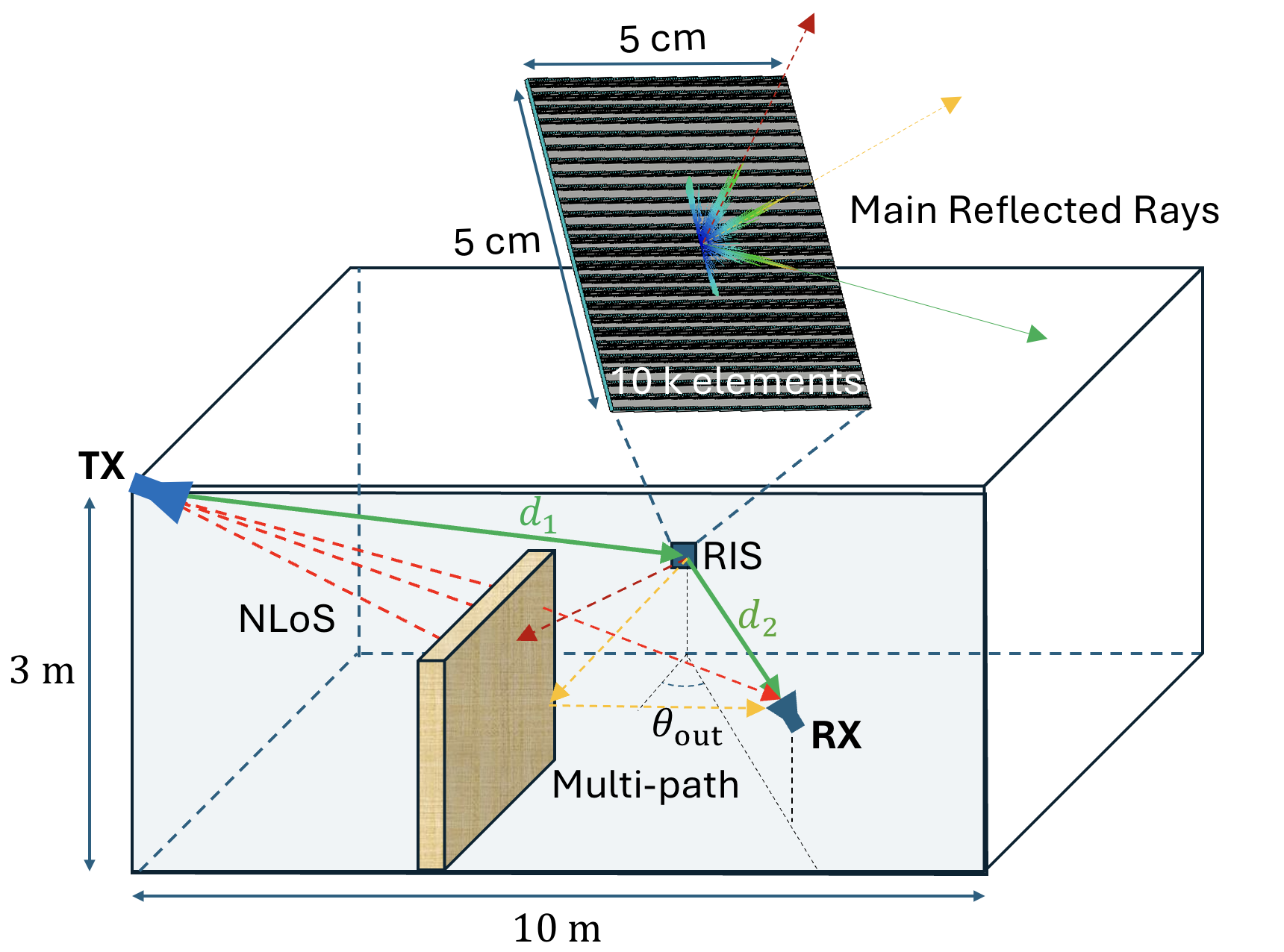
We consider the NLOS indoor communication scenario of Fig. 1 at sub-THz frequencies, where a single-antenna Transmitter (TX) communicates with a single-antenna Receiver (RX) through an RIS mounted on the wall. The metasurface is of size cm2 consisting of sub-wavelength-spaced elements of reconfigurable reflection states. In this paper, we focus on the characterization of an RIS-parameterized NLOS indoor channel for fixed phase configurations of the metasurface. To this end, we have particularly designed the static RIS to redirect incoming normal plane waves into the non-specular reflection at GHz. Note that a realistic indoor scenario implies distances of the order of tens of meters, which indicates electrically extremely large RIS aperture for compensating the high propagation pathloss.
To accurately characterize such indoor propagation channels, a multidomain analysis is required. Multipath characterization using ray tracing algorithms has been lately experimentally proven to be effective at THz frequencies [24, 25]. However, the incorporation of RISs into such ray tracing models is still an open research problem. For a realistic description of this problem, a proper characterization (i.e., amplitude and phase) of the rays emerging from the metasurface is required. The typical approach is to consider idealized behavior of the RIS, which, however, may oversimplify channel characterization. On the other hand, full-wave simulations provide a reliable means for the RIS characterization, allowing us to extract equivalent rays from the RCS patterns; see the inset of Fig. 1. This characterization approach entails the acquisition of all three-dimensional rays emerging from the metasurface, which would heavily overload any ray tracing algorithm if considered in synergy. Fortunately, reasonable approximations can be made to simplify this problem. We will particularly show via full-wave simulations for the designed extremely large RIS, that there exist three main directions where the energy is scattered within our indoor scenario in Fig. 1: i) the RX direction that corresponds to the RIS main beam (green ray); ii) the spurious symmetric beam at the angle (red dashed ray); and iii) the specular reflection leftover (orange dashed rays).
III RIS Design at THz Frequencies
In this section, we present the design of a static RIS at GHz that is intended to tilt by incoming normal plane waves. A -bit unit cell design was chosen which has been shown to provides a good compromise between number of reconfigurable switch elements and reflection performance [17].
III-A Unit Cell Design
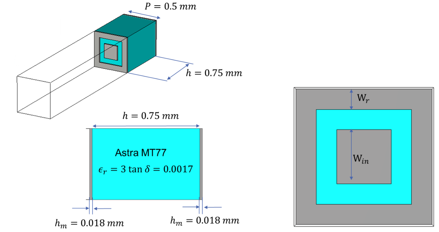
It is quite challenging to produce vias and multilayer structures at THz frequencies, thus, single-layer patch-based unit cells are usually designed, as the one depicted in Fig. 2. The considered substrate is the dielectric Astra MT77 with the standard thickness of mm, which is sufficient to ensure enough mechanical strength for the RIS. The remaining design freedom relies on the patterns of the top layer that provide the required discrete set of phase states. Rectangular shapes are more favourable for production proposes, which led us to fix two building blocks: i) squared metallic patch with size ; and ii) an outer metallic ring with thickness . One key point that needs to be accounted for is that, at these high frequencies, small fabrication imperfections can significantly affect the response of the unit cell. We have confirmed that the developed unit cells are stable enough for dimension variations of the order of m; the latter is a reference value for the maximum precision with conventional manufacturing on Printed Circuit Board (PCB). The designed -bit phase resolution unit cell is illustrated in Fig. 3 for the 4 different states, with the reflection phase given in Table I. We also confirm that the reflection amplitude is below dB.
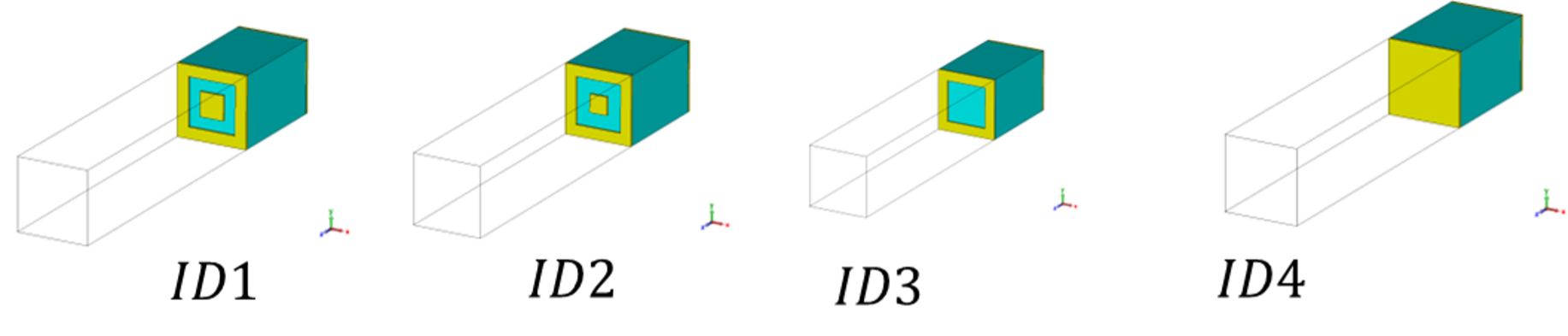
| ID | (mm) | (mm) | arg( (in degrees) |
|---|---|---|---|
| 1 | 0.08 | 0.17 | 0 |
| 2 | 0.08 | 0.13 | 96 |
| 3 | 0.08 | 0 | 184 |
| 4 | All metal | 273 | |
III-B Metasurface Design
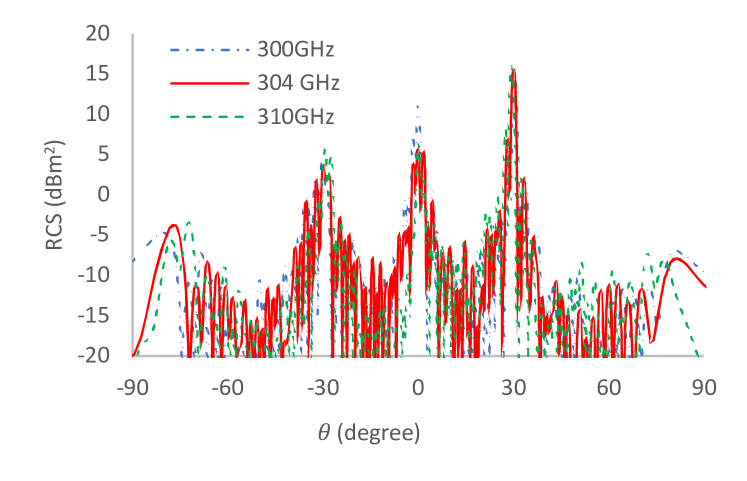
We have used the Finite Difference Time Domain (FTTD) solver of CST Studio Suite to evaluate the performance of a static RIS comprising of the previously designed single-layer patch-based unit cells, thus, of aperture cm2 at GHz, as shown in Fig. 4. The RCS patterns of this RIS are demonstrated in Fig. 4 for different frequencies. It can observed that the maximum RCS value is dBm2 appearing at the desired non-specular direction of , while it is dBm2 at the specular reflection of , and dBm2 at the spurious symmetric direction of . Clearly, the efficiency of the designed RIS is around when compared to the ideal specular reflection. It is also shown in the figure that our RIS can produce very narrow beams (the Half-Power Beam Width (HPBW) of the main beam is only ), which can be well represented by rays equivalent to plane waves.
III-C Far-Field Approximation
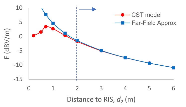
The far-field distance of the designed cm2 RIS aperture is m at the studied GHz band. This implies that, in almost the entire m3 indoor environment, the RX antenna is in the near field-region of the RIS. Interestingly, our simulations showcased that, after m, the far-field approximation results in and an amplitude variation below dB.
IV Indoor Channel Characterization Results
In this section, we discuss two approximations for the multipath components contributed by the designed static RIS.
IV-A Single-Ray Approximation
Let us first consider that only a single ray is generated from the RIS. By applying the bistatic radar equation, we can estimate the received power at a given RX position as follows:
| (1) | ||||
where and represent the TX and RX powers, and are the respective antenna gains, is the wavelength, and and denote the TX-RIS and the RX-RIS distances, respectively, and is the RCS in dB which has been obtained for the designed static RIS in Fig. 4. Note that, in the latter expression, only the amplitude of the RCS is required. It is also important to highlight that the pointing direction of the RIS-generated beam(s) will be affected by the operating frequency according to the following formula [26]:
| (2) |
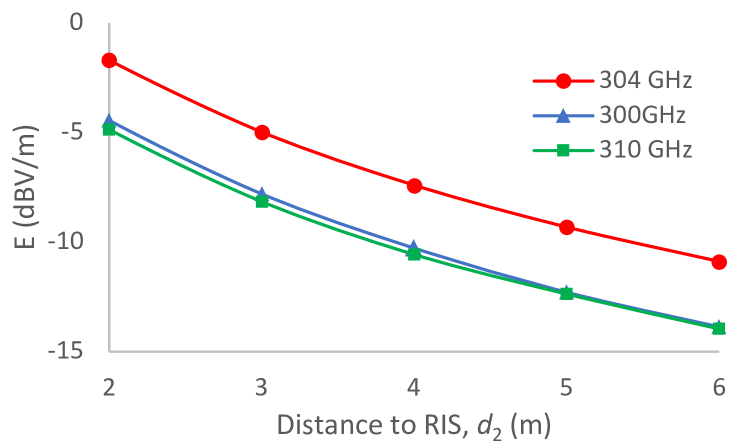
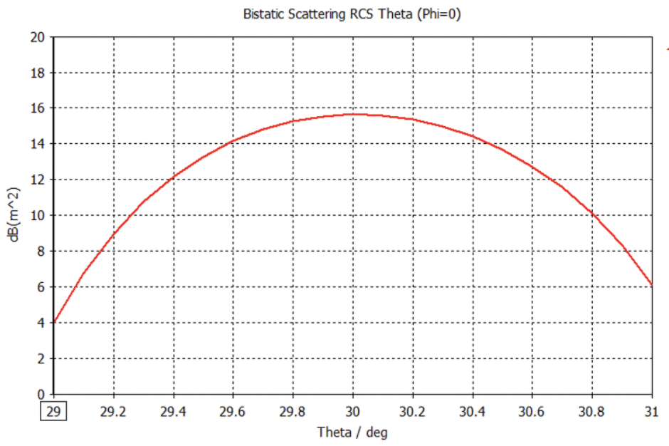
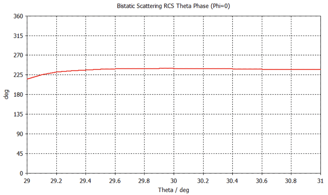
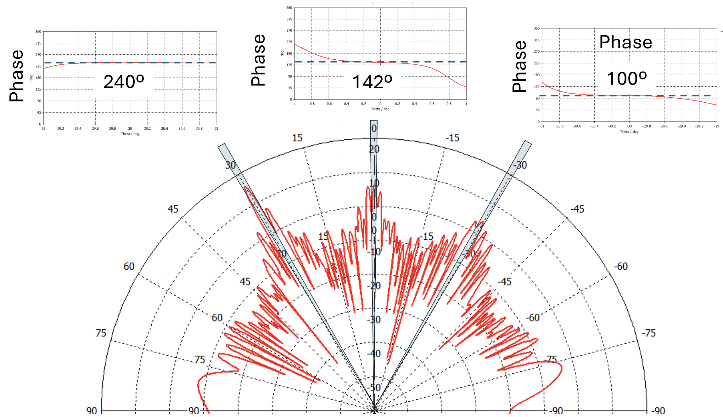
where is a nominal frequency. This formula indicates that, for each frequency, a different ray distribution is obtained. It is noted that many of the exciting ray tracing algorithms do not account for this intrinsic dispersive nature of RISs. In Fig. 6, considering the same observation angle at different RIS-RX distances , it is verified that, within a GHz of bandwidth (i.e., around of the considered operating frequencies), the RCS can vary by dB. It also depicted in Fig. 7 that, within the dB angular range of the main beam direction from the RIS, the phase is nearly constant. This fact validates this single-ray approximation for this region.
IV-B Multi-Ray Approximation
While it is clear that path-loss will reduce the role of the multipath components at sub-THz frequencies, it is still expected that ray interference will play a significant role on the channel behavior [24]. In the case of RIS-assisted wireless communications, we have already shown that spurious rays are inevitable parts of the RIS scattering response [17], which will create additional interference paths that need to be accurately accounted for in the channel modeling and characterization. In Fig. 8, the amplitude and relative phase between all the rays that emerge from the designed RIS when illuminated by a plane wave are demonstrated. It can be seen from the cones along the main reflection directions that there exist three dominant rays originating from the RIS.
V Conclusion
In this paper, we focused on the characterization of an NLOS indoor communication channel at GHz including our RIS with -bit resolution single-layer patch-based unit cells, which was designed to provide a static non-specular reflection to incoming normal plane waves. We have demonstrated that the RIS behavior can be conveniently approximated by a three-ray model, which can be efficiently incorporated within available ray tracing tools. It was also found that the far-field approximation is quite reasonable for much lower RIS-RX distances than those expected in theory.
Acknowledgment
This work was supported by the SNS JU project TERRAMETA under the European Union’s Horizon Europe research and innovation programme under Grant Agreement No 101097101, including top-up funding by UK Research and Innovation (UKRI) under the UK government’s Horizon Europe funding guarantee.
References
- [1] “Terahertz modeling (THz); identification of use cases for THz communication systems,” ETSI GR THz 001, ETSI, 2024.
- [2] IMT-2030 (6G) Promotion Group, “6G vision and candidate technologies,” 2021.
- [3] H. Chen et al., “A tutorial on terahertz-band localization for 6G communication systems,” IEEE Commun. Surveys & Tuts., vol. 24, no. 3, pp. 1780–1815, 2022.
- [4] Z. Wang et al., “A tutorial on extremely large-scale MIMO for 6G: Fundamentals, signal processing, and applications,” IEEE Commun. Surveys & Tuts., early access, 2024.
- [5] N. Shlezinger et al., “Dynamic metasurface antennas for 6G extreme massive MIMO communications,” IEEE Wireless Commun., vol. 28, no. 2, pp. 106–113, 2021.
- [6] T. Gong et al., “Holographic MIMO communications: Theoretical foundations, enabling technologies, and future directions,” IEEE Commun. Surveys & Tuts., vol. 26, no. 1, pp. 196–257, 2024.
- [7] E. Basar et al., “Reconfigurable intelligent surfaces for 6G: Emerging hardware architectures, applications, and open challenges,” IEEE Veh. Techcnol. Mag., vol. 19, no. 3, pp. 27–47, 2024.
- [8] G. C. Alexandropoulos et al., “RIS-enabled smart wireless environments: Deployment scenarios, network architecture, bandwidth and area of influence,” EURASIP J. Wireless Commun. Netw., vol. 103, pp. 1–38, 2023.
- [9] G. C. Alexandropoulos, N. Shlezinger, and P. del Hougne, “Reconfigurable intelligent surfaces for rich scattering wireless communications: Recent experiments, challenges, and opportunities,” IEEE Commun. Mag., vol. 59, no. 6, pp. 28–34, 2021.
- [10] Y. Cheng et al., “RIS-aided wireless communications: Extra degrees of freedom via rotation and location optimization,” IEEE Trans. Wireless Commun., vol. 21, no. 8, pp. 6656–6671, 2022.
- [11] J. An et al., “Stacked intelligent metasurfaces enabling efficient holographic MIMO communications for 6G,” IEEE J. Sel. Areas Commun., vol. 41, no. 8, pp. 2380–2396, 2023.
- [12] K. R. R. Ranasinghe et al., “A doubly-dispersive MIMO channel model parametrized with stacked intelligent metasurfaces,” arXiv preprint:2501.07724, 2025.
- [13] Z. R. Omam et al., “Holographic metasurfaces enabling wave computing for 6G: Status overview, challenges, and future research trends,” arXiv preprint:2501.05173, 2025.
- [14] G. C. Alexandropoulos et al., “Pervasive machine learning for smart radio environments enabled by reconfigurable intelligent surfaces,” Proc. IEEE, vol. 110, no. 9, pp. 1494–1525, 2022.
- [15] K. Keykhosravi et al., “Leveraging RIS-enabled smart signal propagation for solving infeasible localization problems,” IEEE Veh. Technol. Mag., vol. 18, no. 2, pp. 20–28, 2023.
- [16] S. P. Chepuri et al., “Integrated sensing and communications with reconfigurable intelligent surfaces,” IEEE Signal Process. Mag., vol. 40, no. 6, pp. 41–62, 2023.
- [17] G. C. Alexandropoulos et al., “Reconfigurable intelligent surfaces for THz: Signal processing and hardware design challenges,” in Proc. EUCAP, Glasgow, Scotland, 2024.
- [18] S. Matos et al., “Reconfigurable intelligent surfaces for THz: Hardware impairments and switching technologies,” in Proc. ICEAA, Lisbon, Portugal, 2024.
- [19] Y. Zhou et al., “Wideband sub-THz reconfigurable intelligent surface using planar tightly coupled dipoles,” IEEE Ant. Wireless Propag. Lett., early access, 2024.
- [20] G. C. Alexandropoulos et al., “Characterization of indoor RIS-assisted channels at GHz: Experimental measurements, challenges, and future directions,” arXiv preprint:2412.07359, 2024.
- [21] “TERahertz ReconfigurAble METAsurfaces for ultra-high rate wireless communications (TERRAMETA) Project,” https://terrameta-project.eu/.
- [22] L. Pometcu and R. D’Errico, “An indoor channel model for high data-rate communications in D-band,” IEEE Access, vol. 8, pp. 9420–9433, 2020.
- [23] A. Vijayan et al., “5G wireless channel characterization in indoor factory environments: Simulation and validation,” in Proc. IEEE WCNC, Glasgow, UK, 2023.
- [24] J. M. Eckhardt, T. Doeker, and T. Kürner, “Hybrid channel model for low terahertz links in a data center,” IEEE Open J. Commun. Society, vol. 5, pp. 4731–4745, 2024.
- [25] C. Han et al., “Terahertz wireless channels: A holistic survey on measurement, modeling, and analysis,” IEEE Commun. Surveys & Tuts., vol. 24, no. 3, pp. 1670–1707, 2022.
- [26] M. Longbrake, “True time-delay beamsteering for radar,” in Proc. IEEE NAECON, Dayton, USA, 2012, pp. 246–249.