Harnessing Rydberg Atomic Receivers: From Quantum Physics to Wireless Communications
Abstract
The intrinsic integration of Rydberg atomic receivers into wireless communication systems is proposed, by harnessing the principles of quantum physics in wireless communications. More particularly, we conceive a pair of Rydberg atomic receivers, one incorporates a local oscillator (LO), referred to as an LO-dressed receiver, while the other operates without an LO and is termed an LO-free receiver. The appropriate wireless model is developed for each configuration, elaborating on the receiver’s responses to the radio frequency (RF) signal, on the potential noise sources, and on the system performance. Next, we investigate the association distortion effects that might occur, specifically demonstrating the boundaries of linear dynamic regions, which provides critical insights into its practical implementations in wireless systems. Extensive simulation results are provided for characterizing the performance of wireless systems, harnessing this pair of Rydberg atomic receivers. Our results demonstrate that they deliver complementary benefits: LO-free systems excel in proximity operations, while LO-dressed systems are eminently suitable for long-distance sensing at extremely low power levels. More specifically, LO-dressed systems achieve a significant signal-to-noise ratio (SNR) gain of approximately 44 dB over conventional RF receivers, exhibiting an effective coverage range extension over conventional RF receivers by a factor of 150. Furthermore, LO-dressed systems support higher-order quadrature amplitude modulation (QAM) at reduced symbol error rates (SER) compared to conventional RF receivers, hence significantly enhancing wireless communication performance.
Index Terms:
Quantum sensing, quantum radios, Rydberg atomic receivers, wireless communications.I Introduction
Quantum mechanics, emerging in the early 20th century, constitute one of the foundational pillars of modern physics, reshaping our understanding of the nanoscale world. By harnessing the alluring principles of quantum theory, quantum technology has revolutionized our ability to manipulate and control subatomic particles with unprecedented precision, catalyzing advances in communications, computing, and especially precision measurement [1, 2, 3, 4]. One of most pivotal branches of quantum technology is quantum sensing capable of measuring physical quantities with extraordinary sensitivity and accuracy [5, 6]. Rapidly establishing itself as an evolving research frontier, quantum sensing might rely on spin qubits, trapped ions, and flux qubits, positioning itself as a game changer in unlocking new possibilities for applied physics and wireless communications. As quantum sensing continues to evolve, it promises to redefine the boundaries of measurement precision, paving the way for breakthroughs that will significantly enhance the performance of the next-generation wireless communications.
I-A Fundamentals of Rydberg Atoms
Rydberg atoms are characterized by their excitation to certain energy states with large principal atomic numbers, having at least one electron in a highly excited state. This excitation results in having the outer electron far from the ionic core of the Rydberg atom, with the associated dipole moment roughly scaling with its principal atomic number. Having a high electric dipole moment enables Rydberg atoms to engage in strong coupling with even extremely weak radio frequency (RF) fields, making them high-sensitivity sensors for electric fields, particularly for detecting time-varying signals. Specifically, in response to an external RF electric field, a Rydberg atom becomes coupled with this RF field through its high electric dipole moment, and hence the state of the Rydberg atom changes. This event triggers atomic energy level transitions and causes fluctuations in population distribution among these states. These perturbations are precisely monitored by the so-called electromagnetically induced transparency (EIT), which is an all-optical readout technique that probes the Rydberg atomic state [4, 7]. Briefly, the atomic energy levels variations caused by the interaction with the RF field results in EIT spectrum changes, allowing for the accurate extraction of the information conveyed by the electric field. This intricate interplay between the intrinsic properties of Rydberg atoms and EIT-based detection constitutes the fundamental principle that enables Rydberg atoms to function as high-sensitivity quantum sensors.
I-B State-of-the-Art in Rydberg Atomic Receivers
For over four decades, Rydberg atoms have captivated researchers as promising candidates for electric field sensing applications [8, 9, 10]. The realm of Rydberg atom-based electrometry, dedicated to the precise metrology of electric fields, witnessed a period of rapid development between 2010-2014, underscored by several important studies [11, 12, 13]. Specifically, in [11], the idea of employing Rydberg atoms for electric field measurements was proposed, paving the way for establishing the linkage between the optical response characteristics and the International System of Units (SI) [14]. This direct linkage eliminated the need for additional calibration and hence facilitated absolute measurements. This theoretical innovation was experimentally verified in [12], while the authors of [13] further demonstrated the associated self-calibrated traceability over a broad frequency range. Based on these inspirational achievements, numerous academic and industrial research initiatives have launched Rydberg atomic sensor programs across the globe, highlighting the benefits of their sensitivity and versatility, thus positioning them at the forefront of next-generation quantum sensing research.
At the heart of Rydberg atomic receivers lies (i) the ability to diagnose the phase and frequency of weak RF electric fields, and (ii) the enhancement of detection sensitivity. Based on their different responses to RF fields, Rydberg atomic receivers can be categorized into local oscillator (LO)-free [13, 15, 12, 16, 17, 18] and LO-dressed contexts [19, 20, 21, 22, 23]. To be specific, LO-free Rydberg atomic receivers, also referred to as the electrometry, measure the amplitude of the RF field by exploring the so-called Autler-Townes (AT) splitting effect [13, 15, 12, 16, 17, 18]. By measuring the interval of the two split peaks of the EIT spectrum, the Rabi frequency of the RF field can be inferred, thereby allowing for the identification of the RF electric field strength with a high sensitivity approaching the standard quantum limit (SQL). Quantatively, this is on the order of [24, 25]. However, this method is limited to probing the amplitude and polarization of the electric field through optical readout, but fails to measure the phase of the RF signal [12, 17].
By contrast, the LO-dressed Rydberg atomic receiver incorporates an additional RF field that serves as an LO, which is on-resonance with the Rydberg transition. This setup relies on both the EIT and AT effects in Rydberg atoms in order to demodulate a secondary, co-polarized RF field, hence facilitating precise phase measurements by treating the atomic system as a Rydberg atomic mixer [19, 21, 22]. These are also referred to as atomic superheterodyne receivers [20, 23]. The resultant LO-dressed entities achieve an unparalleled sensitivity, capable of detecting RF electric fields on the order of . Consequently, the Rydberg atomic receiver behaves like an integrated compact high-sensitivity antenna, adept at the detection and reception of both amplitude-modulated (AM) [26, 27, 28], frequency-modulated (FM) [26, 28], and phase-modulated (PM) signals [29, 30].
I-C The Advantages
Compared to conventional RF receivers, which rely on traditional antennas and complex electronic front-end components, Rydberg atomic receivers exhibit several remarkable advantages. Firstly, traditional RF receivers utilize antennas to absorb the impinging electromagnetic energy, converting free-space modes into guided currents that are subsequently amplified, filtered, and rectified by front-end circuits before being processed in the analog or digital domains. By contrast, Rydberg atomic receivers do not require any net absorption of the incoming RF field. Instead, the incident RF field alters the energy levels of Rydberg atoms through coherent interactions, which is then imparted to an optical field as amplitude or phase modulations and detected spectroscopically [24]. This eliminates the need for complex and bulky front-end electronic circuits. Secondly, Rydberg atomic receivers are inherently wavelength-independent [31], unlike traditional antennas that must be comparable in size to the wavelength of the RF signal. This feature enables the fabrication of highly efficient electrically small antennas using Rydberg atoms. Thirdly, while conventional high-frequency antennas are inherently directional, Rydberg atomic receivers maintain an omni-directional profile across all wavelengths [32]. Last but not least, Rydberg atomic receivers embrace a broad detection frequency range. The extensive energy level structure of Rydberg atoms allows for their coupling with electromagnetic waves spanning from direct current to Terahertz (THz) frequencies by merely adjusting these energy levels. This tunability facilitates the sensing of various RF bands without necessitating reconfiguration of the hardware platform, which is a significant challenge for traditional RF receivers.
I-D Motivation and Our Contributions
Despite the significant advances concerning Rydberg atomic receivers in the context of quantum sensing, their application in wireless communications is still in its infancy [1, 33, 34, 35, 36]. Initial efforts in [33, 34] investigate atomic multiple-input multiple-output (MIMO) systems, employing multiple vapor cells to construct an equivalent receiver array. In their framework, an LO introduces reference signals, and a phase retrieval process is employed for recovering the phase information of signals arriving from the transmitter (Tx). However, this model might present a departure from the core nature of the LO-dressed Rydberg atomic receivers, whose essence lies in functioning as atomic mixers [20, 22, 23, 36]. These LO-dressed receivers are capable of directly capturing both the amplitude and phase of the incident RF signals at a high precision, without the need for any complex phase retrieval procedures. Therefore, our goal in this treatise is to bridge the gap between quantum physics and wireless communications by developing bespoke mathematical models for both LO-free and LO-dressed Rydberg atomic receivers, in order to unveil their great potential and provide a solid foundation for their potent applications in wireless systems.
To address the challenges stated, this very first study aims for filling the knowledge gap in the-state-of-the-art through the following contributions.
-
•
We develop appropriate wireless models tailored for both LO-free and LO-dressed Rydberg atomic receivers, specifically focusing on the receivers’ responses to the RF signal. Given their different operating mechanisms, the potential noise sources inherent in each receiver type are examined. Furthermore, we derive expressions for their respective signal-to-noise ratios (SNR) and calculate their theoretical capacities through mutual information, providing an intuitive understanding of their performance in practical implementations.
-
•
We investigate the potential distortion effects that might occur when deploying both in LO-free and in LO-dressed Rydberg atomic receivers. For LO-free systems, the distortion is induced by the ambiguous observation in AT splitting owing to the weak Rabi frequency of the RF field. By contrast, as regards LO-dressed systems, we explore the limits of their linear dynamic range and demonstrate that having strong RF Rabi frequencies may push the system beyond this range, resulting in significant distortion effects. As a result, our findings indicate that LO-free systems are more applicable for operation in close proximities, enabling precise detection of signal amplitudes. By contrast, LO-dressed systems are applicable for long-distance scenarios, facilitating the precise measurement of both the amplitude and phase of weak signals transmitted at extremely low power levels.
-
•
By leveraging the QuTiP toolkit [37], we design quantum systems for supporting both LO-free and LO-dressed Rydberg atomic receivers. Specifically, three key metrics are adopted for performance evaluations, namely the SNR, capacity, and symbol error rate (SER). Our numerical results demonstrate that the LO-dressed system achieves a significant SNR gain of approximately over conventional RF receivers, particularly under conditions of extremely low transmit power (e.g., ). Furthermore, the LO-dressed configuration extends the effective coverage range by a factor of 150 compared to its conventional counterparts. Additionally, LO-dressed systems can support higher-order quadrature amplitude modulation (QAM) schemes at a lower SER. These promising results demonstrate that by harnessing the complimentary benefits of LO-free and LO-dressed designs, Rydberg atomic receivers are capable of accommodating diverse transmission ranges, resulting in both improved data rates and reduced SER in wireless systems.
The structure of this paper is organized as follows. In Sec. II, we present the preliminaries, detailing the fundamental operating principles of Rydberg atomic receivers to establish the necessary groundwork for the subsequent discussions. In Sec. III, a pair of models tailored specifically for LO-free and LO-dressed Rydberg atomic receivers are developed, designed for integration into wireless communication systems. In Sec. IV, we investigate the distortion effects that may occur when these receivers are employed in practical wireless systems, elucidating the distinct challenges associated with each receiver type. Sec. V provides numerical results, demonstrating some interesting findings and illustrating the performance of these receivers in various wireless scenarios. Finally, Sec. VI concludes this paper.
II Preliminaries
To provide an intuitive grasp of the Rydberg atomic receiver concept, this section commences by discussing a key physical phenomenon, namely EIT, which drives its operating principle and facilitates an accurate readout for RF field measurements.
II-A Electromagnetically Induced Transparency
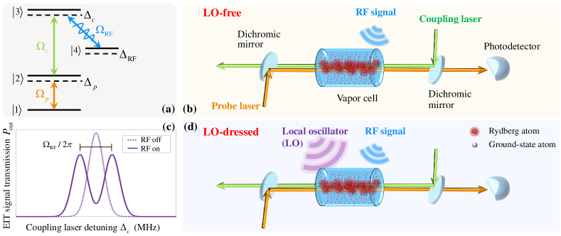
Fig. 1 illustrates the excitation of atoms to Rydberg states within a vapor cell. The vapor cell is populated with Rydberg atoms such as Rubidium (Rb) or Cesium (Cs), which serve as the receiver medium. Within this setup, two counter-propagating laser, namely the probe laser and the coupling laser, are harnessed for manipulating the atomic states. The probe laser facilitates the coupling of the atomic ground state to a low-lying excited state (also referred to as the first excited state), while the coupling laser drives the transition from to a highly excited Rydberg state . When both lasers are precisely resonant, the atoms are coherently pumped into a superposition of and , rendering this state transparent to the probe laser - a phenomenon known as EIT [7]. This reduction in probe absorption under resonant conditions is the hallmark of EIT. By scanning the coupling laser and monitoring the resultant probe absorption, the EIT signal effectively spectroscopically probes the energy of the Rydberg state , as the probe absorption decreases when the coupling laser is aligned with the transition energy.
Upon excitation to the Rydberg state , the atoms become highly sensitive to RF fields that are resonant or nearly resonant with transitions to adjacent Rydberg states, such as . When an RF field induces a resonant coupling between and , the resultant AT effect manifests itself as a splitting of the energy levels, which in turn results in the bifurcation of the EIT signal peak, as depicted in Fig. 1(c). The frequency difference between these two AT-split resonances, denoted by , directly corresponds to the energy difference introduced by the RF field, which is given by
| (1) |
where denotes the Rabi frequency of the RF signal, and represent the frequency of the probe and coupling laser, respectively. Scanning the coupling laser is often preferred, since this way provides a direct measurement of the energy of the Rydberg state without any underlying absorption background.
II-B Probe Laser Transmission
Given the above foundational understanding of the EIT phenomenon, we proceed to the mathematical portrayal of the EIT signal to unveil its defining characteristics. Under the adiabatic approximation of the probe laser transmission, which is in essence given by the intensity of the probe laser measured on the photodetector (PD), it can be characterized through the imaginary part of the susceptibility as [38]
| (2) |
where denotes the intensity of the probe laser associated with its Rabi frequency
| (3) |
In (2) and (3), is the length of the vapor cell, is the wavenumber (wavevector) of the probe laser having a wavelength of , denotes the impedance in the free space, is the diameter of the probe laser, characterizes the dipole moment associated with the transition, and represents the susceptibility, which is given by
| (4) |
where . Furthermore, denotes the instantaneous steady-state density matrix component associated with the transition, is the permittivity in vacuum, and represents the total density of atoms in the cell.
Taking into account the associated spontaneous emission, the dynamics of the atomic system are characterized by the master equation for the four-level density matrix [16]
| (5) |
In the master equation (5), represents the Hamiltonian of the atomic system of interest, which is given by
| (10) |
where and indicate the Rabi frequencies and detunings associated with the probe laser and coupling laser, respectively, as well as represents the detuning of the RF signal. Note that the Rabi frequency in (10) differs for LO-free and LO-dressed Rydberg atomic receivers, which will be elaborated upon later. Still referring to (5), denotes the Lindblad operator that encompasses the decay processes, which is given by
| (15) |
In (15), we have , where is the transition decay rate.
The master equation in (5) is intractable, hence it does not have an analytical solution. Therefore, there is no closed-form expression for . We herein focus on its steady-state solution, achievable by constructing a matrix with the system of equations for . The AT splitting curve can be obtained once we acquire . However, slight adjustments are required depending on the specifics of the Rydberg atomic regimes - regardless of LO-free or LO-dressed. Hence, the technique of measuring the signal’s amplitude and phase using also varies accordingly. The distinct Hamiltonians in both cases result in different forms of the density matrix component . Thus, in the following sections, we present how can be effectively harnessed for each scenario.
III Modeling From Quantum Physics To Wireless Systems
This section presents the transitory solution of the Rydberg atomic receiver from its physical fundamentals to its application in a wireless system, relying on both LO-free and LO-dressed solutions. We commence by considering the transmitter (Tx) as a point source, i.e., by constructing a single-input and single-output (SISO) system. Then, we will methodically extend it to a Rydberg atomic MIMO system.
III-A LO-Free Rydberg Atomic Receiver
III-A1 Receiver’s Response to the RF Signal
The LO-free Rydberg atomic receiver is capable of measuring the amplitude of RF signals, denoted by . When the EIT resonance splits into two peaks, these new transmission maxima are separated by the Rabi frequency of the RF signal associated with the transition. One may refer to Appendix A for verifying this, which is included in the supplementary material of this paper [39]. Then, the Rabi frequency is given explicitly by [20]
| (16) |
where represents the dipole moment associated with the transition. Eq. (16) delineates the core principle of the LO-free Rydberg atomic receiver, indicating that the amplitude of the RF signal can be determined by reading out the separation of the AT splitting associated with the Rabi frequency .
Next, we turn our attention to the modeling of wireless systems. We consider a single Tx serving as a point source, transmitting a unit complex Gaussian signal of transmit power , obeying . After propagating through a complex Gaussian channel , the signal arrives at the vapor cell for measurement, and this process can be modeled as
| (17) |
where represents the received power, while is the background noise. Given the antenna gain at the Tx, denoted by , and the distance between the Tx and receiver (Rx), denoted by , the received power is given by
| (18) |
The RF signal incident upon the vapor cell energizes the Rydberg atoms, facilitating the state transition . As a result, the AT splitting corresponding to the probe beam can be observed in the PD, determining the splitting interval and the Rabi frequency. Therefore, if we let denote our observations from the PD in the face of uncertainty, the signaling process in (17) can be recast as
| (19) |
where represents the noise encompassing all relevant noise sources.
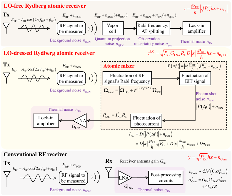
Note that the limitations imposed on the sensitivity of the Rydberg atomic receiver arise from having a finite signal strength in the presence of the noise . The noise can be informally classified as extrinsic and intrinsic noise. As illustrated in Fig. 2, the detailed models of these noise sources are listed as follows.
-
•
(Extrinsic noise) Background noise : The background noise corresponds to the wide-band incoherent background signal imposed by environmental blackbody radiation, whose power is given by . The background noise can be classified as the extrinsic noise.
-
•
(Intrinsic noise) Quantum projection noise (QPN) : The QPN represents a fundamental limit to the precision of quantum sensing, arising from the inherent uncertainty in quantifying the associated energy transition probabilities. This noise is determined by the standard quantum limit and can be modeled as [5, Eq. (38)],[25]
(20) where denotes the number of quantum-mechanically uncorrelated atoms. Furthermore, is an efficiency parameter, where characterizes the accuracy reduction of the readout compared to an ideal readout (). Generally speaking, has a low magnitude and can be reasonably ignored, when applying an extremely large value of [5, 25].
-
•
(Intrinsic noise) Thermal noise : The thermal noise is introduced by the classical post-processing circuits, and the noise power is modeled as
(21) where denotes the Boltzmann constant and is the temperature.
-
•
(Intrinsic noise) Observation uncertainty noise : The performance of the LO-free Rydberg atomic receiver is dependent on the accuracy of the Rabi frequency readout. However, the accuracy of this readout process is often eroded by the noise associated with the observation uncertainty . To be specific, when the Rabi frequency of the RF field decreases, the resultant AT splitting effect becomes less well-defined, as illustrated in Fig. 3. The subtle splitting phenomenon is rather difficult to identify owing to having a blurred interval between the split peaks. This significantly hinders the observation of . As stated in [12], the electric field of the RF signal inside the vapor cell can be measured with an uncertainty of . This uncertainty level may increase, when considering lower transmit power and higher distances . Then, the power of , denoted by , can be calculated by
(22)
Therefore, can be modeled as the sum of these noise sources, represented as an additive complex Gaussian variable with zero mean and variance of
| (23) |
thus yielding that . Furthermore, upon combining (19) and (23), the SNR can be explicitly formulated by
| (24) |

III-A2 Mutual Information
To characterize the capacity bound of the Rydberg atomic system considered, the mutual information is employed as the key metric, which is associated with (19), formulated as
| (25) |
To this end, both the marginal entropy and the conditional entropy are required. We first focus on the marginal entropy . Specifically, the model presented in (19) reflects that the observation variable actually follows a Rayleigh distribution with its scale parameter given by
| (26) |
The p.d.f. of the Rayleigh distribution considered is given by
| (27) |
while the marginal entropy is formulated as
| (28) |
Let us now turn to the conditional entropy . Given , the observation follows a Rician distribution associated with the non-central parameter and scaling parameter . In light of [40], given the Rician factor , the conditional entropy can be formulated as
| (29) |
where and are the modified Bessel function of the first kind of zero and first orders, respectively. For the sake of calculating the average MI, we can approximate the Rician factor by the SNR, i.e., , as shown in (24). Therefore, upon combining (III-A2) and (29), the mutual information is expressed as
| (30) |
III-B LO-Dressed Rydberg Atomic Receiver
In contrast to the LO-free regime that is only capable of measuring the amplitude of the signal, the LO-dressed Rydberg atomic receiver can measure both the amplitude and the phase of an RF signal. Again, this technique relies on the concept of a Rydberg atom-based mixer [20, 22, 23]. Briefly, an additional reference signal, also known as an LO being on-resonance with the Rydberg transition, is introduced into the vapor cell to control the down-conversion dynamics of the Rydberg atoms. This exposes the Rydberg atoms to the EIT/AT effect in order to demodulate the RF signal to be measured. The frequency difference and the phase difference between the RF signal and the LO can be optically traced. In what follows, we first elaborate on the underlying physical principles, and subsequently examine their compatibility with wireless communication systems.
III-B1 Receiver’s Response to the RF Signal
As regards to the LO-dressed Rydberg atomic receiver, we specify the RF signal and the LO signal respectively as
| (31a) | |||
| (31b) | |||
where , , and denote their own amplitudes (where we define ), frequencies, and phases, with the frequency and phase differences given by and , respectively. The superposition field can be formulated as
| (32) |
which indicates that the non-linear response of the Rydberg atoms to the superposition field can be treated as an envelope-detection process. When we have , the main frequency component of the superposition field’s envelope is determined by the difference , where the upper harmonics may be deemed negligible [22, 23]. By performing the second-order Taylor expansion of (III-B1) at point with respect to , we arrive at
| (33) |
In (33), the resonant term, i.e., , induces an AT splitting effect, hence reducing the peak of the EIT line, and the lower frequency term, i.e., , modulates the amplitude of the resonance.
Furthermore, to provide a closed-form expression for , we have to obtain by solving the master equation in (5). Accordingly, in (10) is further refined as , and . However, the density matrix component is excessively complex and, as such, only lends itself to numerical simulations, for example, by using QuTip [37]. To unveil its underlying physics model more intuitively, we derive an analytical approximation. In particular, the states and are metastable, exhibiting significantly extended lifetimes, resulting in spontaneous emission rates that are markedly lower than those of state (). Therefore, within this approximation, it is reasonable to set [20]. Additionally, we consider only the resonant case where the probe laser, coupling laser, and LO are in resonance with the corresponding atomic energy levels. This implies that their detunings are . Under these circumstances, the density matrix component simplifies to (the time index “” is dropped for notational conciseness)
| (34) |
Upon substituting (III-B1) into (2), we obtain
| (35) |
where represents the average intensity of the probe laser. Furthermore, models the absorption coefficient of the probe laser, can be understood as the amplitude of the three-level EIT spectrum, is a key intrinsic coefficient characterizing the slope induced when the AT splitting of the EIT peak shifts the on-resonance point to the slope of each EIT line, represents the intrinsic gain coefficient associated with the density matrix component , represents the half-width at half-maxima (HWHM) of a four-level system, as well as the function is a normalized Lorentzian function with as the variable and representing the HWHM, where corresponds to the full-width at half-maxima (FWHM). For detailed derivations, please refer to Appendix B in the supplementary material accompanying this paper [39].
Then, the LO-dressed Rydberg atomic receiver measures an RF signal in form of an optical readout, represented by
| (36) |
where is the amplitude of the single-sided Fourier spectrum at the frequency when performing the Fourier transform over . The Rabi frequency of the RF signal is then given by
| (37) |
which thus provides us with an RF signal amplitude of .
Eqs. (III-B1) and (37) are at the heart of the LO-dressed Rydberg atomic receiver. In sharp contrast to the LO-free context, the LO-dressed one concentrates on measuring the amplitude of the single-side Fourier spectrum of , i.e., , at the frequency . Then, the phase difference can be extracted from by employing a homodyne detector [41, 42, 20], retrieving the RF signal phase according to . Thus, the RF signal can be accurately recovered. Additionally, both and can be directly attained from the optical spectrum. This technique efficiently reduces the electric-field measurement to an optical-frequency readout, while ensuring its International System of Units (SI) traceability [4]. Furthermore, the probe laser transmission is received by a PD and converted into an output photocurrent signal. The relationship between the alternating current (AC) component of the probe laser power, i.e., , and the photocurrent is given by , where is the photodiode’s responsivity, with units of A/W. The carrier of the RF signal is transferred from the probe laser to the photocurrent generated by the PD. Consequently, the instantaneous power associated with the AC component in the photocurrent output from the PD is given by , where is the output impedance of the PD.
Next, we consider the application of the LO-dressed Rydberg atomic receiver in a wireless communication system. Specifically, given a complex Gaussian transmitted signal, the observation at the PD after encountering the channel is given by
| (38) |
where denotes the gain of the photocurrent after processing by the subsequent circuits (such as a low-noise amplifier, LNA), and models the noise encompassing all relevant noise sources. For the LO-dressed Rydberg atomic receiver illustrated in Fig. 2, the noise comes primarily from the extrinsic background noise , and from the intrinsic noise. The intrinsic noise sources encompass the QPN , the photon shot noise (PSN) generated during the transformation of the RF signal to photocurrent, and from the thermal noise introduced by post-processing circuits. However, the QPN can be neglected in this case [5, 25].
-
•
(Extrinsic noise) Background noise : After contamination by the background noise, the RF signal incident upon the vapor cell can be represented as . After being mixed, is refined as
(39) Note that herein we use instead of for consistency with (38), since it more closely reflects the received power; both terms represent the signal amplitude.
-
•
(Intrinsic noise) Photon shot noise : In the transformation of the RF signal to photocurrent, the PSN is introduced, which thus yields [23]
(40) The photocurrent power is written explicitly as [23]
(41) where represents the power of , modeled as
(42) where is the average photocurrent, which can be calculated by
(43) In (43), denotes the photon efficiency with no units and gives the frequency of the probe laser.
-
•
(Intrinsic noise) Thermal noise : The thermal noise is introduced by the LNA and by the post-processing circuits, which can be modeled in the same way as in (21).
Then, the output power of the LNA is given by
| (44) |
Therefore, in the LO-dressed context, the noise can be modeled by an additive complex random variable with zero mean and variance , namely . According to (III-B1), the SNR can be formulated by
| (45) |
III-B2 Mutual Information
The analysis is similar to that of conventional systems, but relies on different coefficients. The mutual information of the LO-dressed system, denoted by , is calculated by
| (46) |
where denotes the exponential integral function [43].
IV Distortion Effect
Rydberg atomic receivers - both the LO-free and LO-dressed schemes - benefit from the large dipole moment of Rydberg atoms, endowing them with the ability to measure extremely weak RF signals; yet, each can only achieve its full potential when configured within its appropriate range. Given their distinct atomic responses to the RF field, their operating conditions in wireless communication systems also differ. This section aims for characterizing the distortion effects associated with these two types of Rydberg atomic receivers by simulation results, thereby highlighting their respective operating conditions, when used for wireless systems. Before we proceed, it is essential to clarify some critical parameters related to our simulation results. Unless otherwise specified for a particular type of Rydberg atomic receiver, these parameters apply to both types of receivers.
We employ the QuTiP toolkit [37] for simulating the quantum system considered, where the parameters are taken from [12, 20, 23] to ensure their rationale. To be specific, the vapor cell is long and comprises ground state atoms at a total density of . The four-level energy system illustrated in Fig. 1(a) is realized by taking into account the following four states in a Cs atom: , in which the Rydberg state has an inverse lifetime of , and the Rydberg state has an inverse lifetime of . For the two lowest states of and , the lifetimes are and , respectively. The dipole moment associated with a transition is , and for transition, with representing the elementary charge and for the Bohr radius. The carrier frequency of the RF signal is . For the probe laser, the wavelength is , and the beam diameter is , yielding the Rabi frequency of . For the coupling laser, the wavelength is , the beam diameter is , and the Rabi frequency is . The bandwidth of the atomic system is . The permittivity in vacuum is , and the impedance in free space is given by . Regarding the LO-free Rydberg atomic receiver, the Rabi frequency of the RF field is . For the LO-dressed system, the Rabi frequency of the RF field is and for the LO field. The frequency difference is given by . The remaining parameters are specified as follows: , , , , and .
IV-A LO-Free Rydberg Atomic Receiver
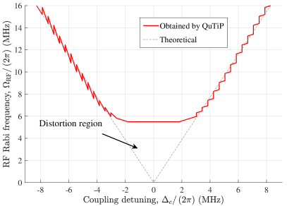
As regards to the LO-free Rydberg atomic receiver, the distortion may arise from ambiguous observations caused by a high level of uncertainty when the Rabi frequency of the RF field is weak, and hence the AT splitting interval cannot be accurately identified. If we fix in Fig. 3 and scan , we obtain the trend of the AT splitting interval upon varying the Rabi frequency , as shown in Fig. 4 (actually a top-down view of Fig. 3). Specifically, in Fig. 4, the dashed gray line represents the theoretical interval between a pair of AT splitting peaks, while the jagged solid red curves are obtained using the QuTiP toolkit [37]. The jagged profile of the curves is due to perturbations in the quantum system during the solution of the master equation (5), reflecting the step-wise process involved in locating the EIT spectrum peaks. Intuitively, we observe that as the Rabi frequency decreases, the interval between the two AT splitting peaks gradually narrows. However, this interval does not reduce to zero; instead, it saturates at a certain Rabi frequency, around . Below this threshold, the EIT spectrum no longer exhibits two peaks, when scanning , indicating that the LO-free system has entered its distortion region. Within this distortion region, only a single-peaked EIT line is observed.
The simulation results in Fig. 3 and Fig. 4 provide insights for wireless system implementations: the LO-free Rydberg atomic receiver is capable of detecting relatively strong RF signals (‘strong’ is relative to the LO-dressed system, and compared to traditional receivers, it can still detect weak signals); however, the detection of extremely weak signals may push the-LO-free system into its distortion region, leading to degraded performance. Furthermore, the boundary between strong and weak signal detection may be related to the HWHM of the EIT spectrum. The HWHM may be difficult to formulate analytically, as it is dependent upon the specific configuration of the quantum system and can be determined experimentally [20].
IV-B LO-Dressed Rydberg Atomic Receiver
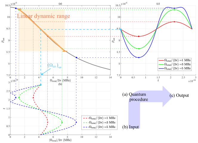
When the coupling laser is locked at the transmission frequency between states and , i.e., when , Fig. 5(a) illustrates the probe laser transmission versus the total Rabi frequency , as formulated in (2). When varies versus the time , as seen in Fig. 5(c), the temporal relationship between and is depicted in Fig. 5(b). Specifically, as observed in Fig. 5(a), decreases upon increasing . Within the range where the orange line coincides with the black curve, a near-linear relationship is observed between and . This range of the Rabi frequency can therefore be considered as the linear dynamic range of the LO-dressed framework. Conversely, when is either too strong or too weak, exhibits a non-linear relationship with . The significance of this for wireless communication is that when the RF signal intensity is too high (for instance, if the transmission power is very high), the LO-dressed receiver may not function well. This will be examined thoroughly in Sec. V.
Typically, we aim for designing the LO-dressed system for allowing it to operate within linear region, i.e., within the orange square of Fig. 5(a). This also aligns with the fundamental design objective of the LO-dressed Rydberg receiver: to maximize the slope , thereby extending the linear dynamic range. The slope serves as an approximate fit for the relationship between and . However, the closed-form analyses of the bounds of the linear dynamic range proves challenging due to the intractability of the master equation in (5). This is caused by the uncertainties in the quantum system, such as their decay constants, transition probabilities, and atomic responses. While the exact range limits may be elusive, one viable approach is to simulate this quantum system using the QuTiP toolkit [37], allowing us to plot their curves and infer an approximate linear dynamic range.
V Numerical Results
V-A Simulation Setup
This section provides numerical results for characterizing the performance of a wireless system relying on both LO-free and LO-dressed receivers. In addition to the quantum parameters presented in Sec. IV, some other parameters associated with wireless systems are specified as follows. We assume that the Tx is equipped with a dipole antenna having an antenna gain of . The RF signal is transmitted at a power of , and arrives at the Rydberg atomic receiver over a distance of . The background noise power is . For comparison with conventional RF receivers, the receiver antenna gain shown in Fig. 2 is given by , and its effective area is calculated by .
V-B SNR Performance
Fig. 6 portrays the SNR performance versus distance of both the LO-free and LO-dressed Rydberg atomic receivers, which are compared to conventional RF receivers for different transmit powers . The “Theoretical LO-dressed” curve represents the theoretical SNR specified in (45), whereas the “LO-free” and “Practical LO-dressed” curves are obtained through simulations using the QuTiP toolkit [37]. Some intriguing phenomena may be observed. Firstly, the SNR performance curve of the LO-free receiver discontinues beyond about 10 meters. This can be attributed to the increased free-space path loss versus distance, which is due to attenuating the RF Rabi frequency . Accordingly, as indicated by the SNR expression in (24), the uncertainty level is increased for an attenuated , leading to a significant degradation in SNR. As continues to decay, the system enters its distortion region, as shown in Fig. 4, leading to the LO-free Rydberg atomic receiver’s inability to read out any AT splitting interval. Secondly, the LO-dressed system exhibits poor SNR performance at short distances (e.g., within a few meters). This degradation, although counterintuitive, occurs because the strong RF Rabi frequency pushes the system beyond its linear dynamic range, as illustrated in Fig. 5. Thirdly, it is evident that both the LO-free and LO-dressed Rydberg atomic receivers consistently outperform conventional RF receivers in terms of the SNR required. For instance, at a transmit power of and a distance of , the LO-dressed atomic receiver achieves an SNR that is approximately higher than that of a conventional receiver. Additionally, the LO-dressed receiver extends the effective coverage by approximately 1,500 meters in comparison to conventional RF receivers.
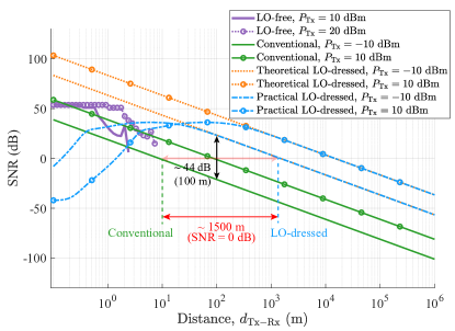
Fig. 6 also highlights their amazing capabilities of detecting weaker RF signals over extended ranges, while achieving higher SNR at a reduced transmit power as a benefit of their increased sensitivity. Specifically, the LO-free and LO-dressed systems exhibit complementary strengths: in close proximity (e.g., ), the LO-free system overcomes the performance erosion of LO-dressed systems experienced beyond their linear dynamic range, achieving an SNR advantage of up to compared to conventional RF receivers. Therefore, we conclude that LO-dressed systems outperform their LO-free counterparts at larger distances (e.g., ), revealing outstanding detection capabilities in the distance-range, where LO-free systems are less effective. This complementary functionality is crucial for optimizing the performance of wireless communication systems relying on Rydberg atomic receivers, enabling robust signal detection across diverse coverage distances.
V-C Achievable Capacity
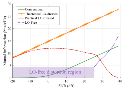
Fig. 7 illustrates the theoretical mutual information versus the received SNR. The LO-free system follows the mutual information formulated in (30), while the LO-dressed system obeys the result presented in (46). Given the distortion present in both LO-free and LO-dressed scenarios, their quantum parameters are obtained via QuTiP and Monte Carlo simulations. As expected, an increase in the received SNR leads to a significant enhancement in mutual information. More specifically, the practical LO-dressed configuration is closely aligned with the theoretical LO-dressed capacity at low SNR levels. However, as the SNR increases, the practical LO-dressed capacity precipitously declines beyond a certain threshold, entering its distortion region. By contrast, the LO-free system initially operates within the distortion region at a low SNR level, but exhibits substantial capacity improvement beyond this region. These behaviors stem from the distinct atomic responses of LO-free and LO-dressed systems when exposed to varying RF fields. Different transmit power levels yield varying RF Rabi frequencies, which in turn results in specific operating or distortion regions at an identical SNR.
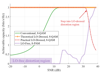
In Fig. 8, we examine the influence of modulation schemes on the achievable capacity. More specifically, the LO-dressed and the conventional systems utilize 8-order quadrature amplitude modulation (8-QAM), while the LO-free systems employ 8-order pulse amplitude modulation (8-PAM) due to its fixed-amplitude nature. Given that the theoretical performance limit for both 8-QAM and 8-PAM is , it is evident that all systems approach saturation at this level, as the transmit power increases. Firstly, the LO-dressed systems exhibit a non-negligible capacity at low SNR levels. As the SNR increases, the capacity of LO-dressed systems declines, corroborating the findings seen in Fig. 7, as expected outside the linear dynamic range. Secondly, although LO-free systems exhibit superior SNR performance compared to conventional RF receivers (shown in Fig. 6), their capacities achieved for constant-amplitude 8-PAM are lower than for 8-QAM. This is because LO-free systems measure only the amplitude of the RF field, precluding the utilization of phase information. By contrast, at a higher SNR, the LO-free system achieves significant capacity enhancements. These observations underscore the complementary potential of LO-dressed and LO-free configurations in optimizing wireless systems across different power levels, leveraging their distinct atomic response characteristics for maximizing the system capacity.
Additionally, the results obtained in Fig. 7 and Fig. 8 convey more promising insights: To achieve the same rate, the LO-dressed configuration requires a much lower received SNR compared to the conventional RF receiver. Physicists have long demonstrated that Rydberg atomic receivers exhibit exceptional sensitivity to RF signals, and this sensitivity translates into practical engineering advantages – the reduced SNR requirement. This implies that in practical implementations we can either reduce the transmit power or extend the transmission distance.
V-D SER Performance
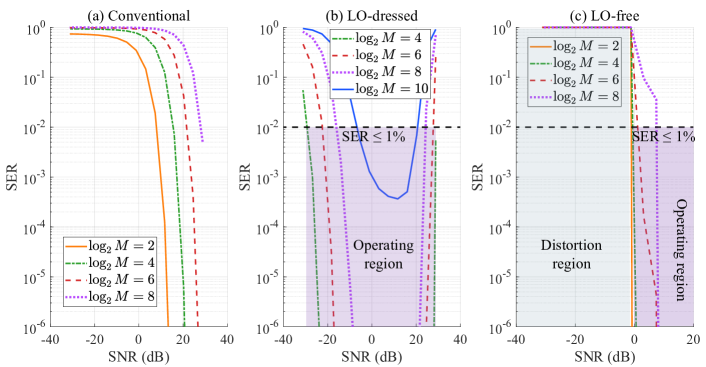
Fig. 9 illustrates the SER performance versus the SNR for different modulation orders . The SER of PAM is calculated according to [44, Pg. 266, Eq. (5.246)], and the SER of the QAM can be evaluated based on [44, Pg. 278, Eq. (5.279)]. Firstly, the three subplots clearly illustrate that, regardless of the receiver type, higher modulation orders result in an increased SER. This aligns with conventional expectations. Both the LO-dressed and LO-free configurations require a lower SNR to achieve a SER of compared to conventional RF receivers, while also supporting higher modulation orders, such as the QAM order of for the LO-dressed system. Once the SER is below , the residual errors may be readily cleaned up by powerful error correction codes [45]. More intriguingly, their own performance as functions of the SNR differ. To be specific, as depicted in Fig. 9(b), the SER performance of the LO-dressed receiver initially improves with an increased SNR, but subsequently deteriorates as SNR continues to rise. This degradation occurs because a high received SNR drives the LO-dressed system beyond its linear dynamic range into a distortion region. This superior performance experienced in the linear dynamic range is attributed to the high sensitivity of LO-dressed systems, which facilitates accurate discrimination of the constellation points and exhibits remarkable robustness against noise. By contrast, as shown in Fig. 9(c), the LO-free system enters its operating region at a specific SNR threshold, where it exhibits a favorable SER performance level. It is also evident that the SER of the LO-free receiver is substantially better than that of conventional RF receivers. Additionally, when the SER of Rydberg atomic receivers approaches 1, this is primarily attributed to the challenges in identifying constellation points at higher modulation orders , and owing to mismatches in quantum parameters that prevent the operation within the operating region. Thus, careful parameter tuning is crucial for fully exploiting the benefits of the quantum sensing system.
In the design of wireless communication systems, there is a perpetual quest for increased data rates a reduced SER. However, this pursuit is hindered by the inherent trade-off where higher-order modulations inevitably lead to increased SER, since “we cannot have the best of both worlds”. Fortunately, the advent of Rydberg atomic receivers presents a promising way forward.
VI Conclusions
An avenue of realizing true quantum-aided wireless systems has been proposed by developing customized models for Rydberg atomic receivers. We investigated the characteristics of both LO-free and LO-dressed Rydberg atomic receivers, focusing on the linear dynamic range and distortion effects. Through extensive numerical simulations, we characterized our models by evaluating their key performance metrics, including their SNR, system capacities, and SER. Accordingly, a few valuable insights were drawn in terms of their deployment strategies in wireless communication systems.
Despite these contributions, the current convenient framework proposed in this paper represents only the beginning of a broader exploration into quantum sensing aided wireless communications. Some unresolved issues remain, warranting further investigations, and we list a few of them below.
-
1)
Wideband Designs for Rydberg Atomic Receivers: While this study considered Rydberg atomic receivers operating within a bandwidth of , expanding to broader bandwidths may push these systems beyond their linear dynamic range. Therefore, developing wideband designs, along with bespoke signal processing techniques for distortion elimination, are essential for their practical implementations.
-
2)
Rydberg Atomic MIMO: Although similar concepts have been explored in [33], the practical deployment of multiple vapor cells poses significant challenges. Future research should concentrate on more efficient yet compact implementations of Rydberg Atomic MIMO systems, for example, through the use of multiple probe lasers and a single coupling laser within a single vapor cell [18].
-
3)
The current study is based on standard configurations established by the physics community. For the wireless research community, further sophisticated designs are required for mitigating the hardware impairments, for example, stabilization and calibration of the probe/coupling laser, and accurate transmit power control, so that the system can operate within its linear domain.
References
- [1] L. Hanzo, Z. Babar, Z. Cai, D. Chandra, I. B. Djordjevic, B. Koczor, S. X. Ng, M. Razavi, and O. Simeone, “Quantum information processing, sensing and communications: Their myths, realities and futures,” arXiv preprint: 2412.00987, 2024. [Online]. Available: https://arxiv.org/abs/2412.00987
- [2] X. Zhou, A. Shen, S. Hu, W. Ni, X. Wang, E. Hossain, and L. Hanzo, “Towards quantum-native communication systems: New developments, trends, and challenges,” arXiv preprint: 2311.05239, 2023. [Online]. Available: https://arxiv.org/abs/2311.05239
- [3] A. G. J. MacFarlane, J. P. Dowling, and G. J. Milburn, “Quantum technology: the second quantum revolution,” Philos. Transact. A Math. Phys. Eng. Sci., vol. 361, no. 1809, pp. 1655–1674, Jun. 2003.
- [4] N. Schlossberger, N. Prajapati, S. Berweger, A. P. Rotunno, A. B. Artusio-Glimpse, M. T. Simons, A. A. Sheikh, E. B. Norrgard, S. P. Eckel, and C. L. Holloway, “Rydberg states of alkali atoms in atomic vapour as SI-traceable field probes and communications receivers,” Nat. Rev. Phys., Sep. 2024.
- [5] C. L. Degen, F. Reinhard, and P. Cappellaro, “Quantum sensing,” Rev. Mod. Phys., vol. 89, p. 035002, Jul. 2017.
- [6] S. Pirandola, B. R. Bardhan, T. Gehring, C. Weedbrook, and S. Lloyd, “Advances in photonic quantum sensing,” Nat. Photonics, vol. 12, no. 12, pp. 724–733, Nov. 2018.
- [7] M. Fleischhauer, A. Imamoglu, and J. P. Marangos, “Electromagnetically induced transparency: Optics in coherent media,” Rev. Mod. Phys., vol. 77, pp. 633–673, Jul. 2005.
- [8] T. W. Ducas, W. P. Spencer, A. G. Vaidyanathan, W. H. Hamilton, and D. Kleppner, “Detection of far‐infrared radiation using Rydberg atoms,” Appl. Phys. Lett., vol. 35, no. 5, pp. 382–384, Sep. 1979.
- [9] H. Figger, G. Leuchs, R. Straubinger, and H. Walther, “A photon detector for submillimetre wavelengths using Rydberg atoms,” Opt. Commun., vol. 33, no. 1, pp. 37–41, Apr. 1980.
- [10] A. Osterwalder and F. Merkt, “Using high Rydberg states as electric field sensors,” Phys. Rev. Lett., vol. 82, pp. 1831–1834, Mar. 1999. [Online]. Available: https://link.aps.org/doi/10.1103/PhysRevLett.82.1831
- [11] J. A. Gordon, C. L. Holloway, S. Jefferts, and T. Heavner, “Quantum-based SI traceable electric-field probe,” in Proc. IEEE Int. Symp. Electromagn. Compat., Fort Lauderdale, FL, USA, Jul. 2010, pp. 321–324.
- [12] J. A. Sedlacek, A. Schwettmann, H. Kübler, R. Löw, T. Pfau, and J. P. Shaffer, “Microwave electrometry with Rydberg atoms in a vapour cell using bright atomic resonances,” Nat. Phys., vol. 8, no. 11, pp. 819–824, Nov. 2012.
- [13] C. L. Holloway, J. A. Gordon, S. Jefferts, A. Schwarzkopf, D. A. Anderson, S. A. Miller, N. Thaicharoen, and G. Raithel, “Broadband Rydberg atom-based electric-field probe for SI-traceable, self-calibrated measurements,” IEEE Trans. Antennas Propag., vol. 62, no. 12, pp. 6169–6182, Dec. 2014.
- [14] M. Stock, “The revision of the SI–towards an international system of units based on defining constants,” Meas. Tech., vol. 60, pp. 1169–1177, Mar. 2018.
- [15] A. K. Robinson, N. Prajapati, D. Senic, M. T. Simons, and C. L. Holloway, “Determining the angle-of-arrival of a radio-frequency source with a Rydberg atom-based sensor,” Appl. Phys. Lett., vol. 118, no. 11, p. 114001, Mar. 2021.
- [16] A. P. Rotunno, C. L. Holloway, N. Prajapati, S. Berweger, A. B. Artusio-Glimpse, R. Brown, M. Simons, A. K. Robinson, B. N. Kayim, M. A. Viray, J. F. Jones, B. C. Sawyer, R. Wyllie, T. Walker, R. W. Ziolkowski, S. R. Jefferts, S. Geibel, J. Wheeler, and E. Imhof, “Investigating electromagnetically induced transparency spectral lineshape distortion due to non-uniform fields in Rydberg-atom electrometry,” J. Appl. Phys., vol. 134, no. 8, p. 084401, Aug. 2023.
- [17] J. A. Sedlacek, A. Schwettmann, H. Kübler, and J. P. Shaffer, “Atom-based vector microwave electrometry using Rubidium Rydberg atoms in a vapor cell,” Phys. Rev. Lett., vol. 111, p. 063001, Aug 2013.
- [18] J. S. Otto, M. K. Hunter, N. Kjærgaard, and A. B. Deb, “Data capacity scaling of a distributed Rydberg atomic receiver array,” J. Appl. Phys., vol. 129, no. 15, p. 154503, Apr. 2021.
- [19] R. Mao, Y. Lin, Y. Fu, Y. Ma, and K. Yang, “Digital beamforming and receiving array research based on Rydberg field probes,” IEEE Trans. Antennas Propag., vol. 72, no. 2, pp. 2025–2029, Feb. 2024.
- [20] M. Jing, Y. Hu, J. Ma, H. Zhang, L. Zhang, L. Xiao, and S. Jia, “Atomic superheterodyne receiver based on microwave-dressed Rydberg spectroscopy,” Nat. Phys., vol. 16, no. 9, pp. 911–915, Jun. 2020.
- [21] Y. Wang, F. Jia, J. Hao, Y. Cui, F. Zhou, X. Liu, J. Mei, Y. Yu, Y. Liu, J. Zhang, F. Xie, and Z. Zhong, “Precise measurement of microwave polarization using a Rydberg atom-based mixer,” Opt. Express, vol. 31, no. 6, pp. 10 449–10 457, Mar. 2023.
- [22] M. T. Simons, A. H. Haddab, J. A. Gordon, and C. L. Holloway, “A Rydberg atom-based mixer: Measuring the phase of a radio frequency wave,” Appl. Phys. Lett., vol. 114, no. 11, p. 114101, Mar. 2019.
- [23] F. Wu, Q. An, Z. Sun, and Y. Fu, “Linear dynamic range of a Rydberg-atom microwave superheterodyne receiver,” Phys. Rev. A, vol. 107, p. 043108, Apr. 2023.
- [24] C. T. Fancher, D. R. Scherer, M. C. S. John, and B. L. S. Marlow, “Rydberg atom electric field sensors for communications and sensing,” IEEE Trans. Quantum Eng., vol. 2, pp. 1–13, Mar. 2021.
- [25] K. C. Cox, D. H. Meyer, F. K. Fatemi, and P. D. Kunz, “Quantum-limited atomic receiver in the electrically small regime,” Phys. Rev. Lett., vol. 121, p. 110502, Sep. 2018.
- [26] C. Holloway, M. Simons, A. H. Haddab, J. A. Gordon, D. A. Anderson, G. Raithel, and S. Voran, “A multiple-band Rydberg atom-based receiver: AM/FM stereo reception,” IEEE Antennas Propag. Mag., vol. 63, no. 3, pp. 63–76, Jun. 2021.
- [27] D. H. Meyer, K. C. Cox, F. K. Fatemi, and P. D. Kunz, “Digital communication with Rydberg atoms and amplitude-modulated microwave fields,” Appl. Phys. Lett., vol. 112, no. 21, p. 211108, May 2018.
- [28] D. A. Anderson, R. E. Sapiro, and G. Raithel, “An atomic receiver for AM and FM radio communication,” IEEE Trans. Antennas Propag., vol. 69, no. 5, pp. 2455–2462, May 2021.
- [29] C. L. Holloway, M. T. Simons, J. A. Gordon, and D. Novotny, “Detecting and receiving phase-modulated signals with a Rydberg atom-based receiver,” IEEE Antennas Wirel. Propag. Lett., vol. 18, no. 9, pp. 1853–1857, Sep. 2019.
- [30] Y. Cai, S. Shi, Y. Zhou, Y. Li, J. Yu, W. Li, and L. Li, “High-sensitivity Rydberg-atom-based phase-modulation receiver for frequency-division-multiplexing communication,” Phys. Rev. Appl., vol. 19, p. 044079, Apr. 2023.
- [31] D. H. Meyer, Z. A. Castillo, K. C. Cox, and P. D. Kunz, “Assessment of Rydberg atoms for wideband electric field sensing,” J. Phys. B: At. Mol. Opt. Phys., vol. 53, no. 3, p. 034001, Jan. 2020.
- [32] S. Yuan, M. Jing, H. Zhang, L. Zhang, L. Xiao, and S. Jia, “Isotropic antenna based on Rydberg atoms,” Opt. Express, vol. 32, no. 5, pp. 8379–8388, Feb. 2024.
- [33] M. Cui, Q. Zeng, and K. Huang, “Towards atomic MIMO receivers,” arXiv preprint: 2404.04864, 2024. [Online]. Available: https://arxiv.org/abs/2404.04864
- [34] ——, “IQ-aware precoding for atomic MIMO receivers,” arXiv preprint: 2408.14366, 2024. [Online]. Available: https://arxiv.org/abs/2408.14366
- [35] T. Gong, A. Chandra, C. Yuen, Y. L. Guan, R. Dumke, C. M. S. See, M. Debbah, and L. Hanzo, “Rydberg atomic quantum receivers for classical wireless communication and sensing,” arXiv preprint: 2409.14501, 2024. [Online]. Available: https://arxiv.org/abs/2409.14501
- [36] T. Gong, J. Sun, C. Yuen, G. Hu, Y. Zhao, Y. L. Guan, C. M. S. See, M. Debbah, and L. Hanzo, “Rydberg atomic quantum receivers for classical wireless communications and sensing: Their models and performance,” arXiv preprint: 2412.05554, 2024. [Online]. Available: https://arxiv.org/abs/2412.05554
- [37] J. R. Johansson, P. D. Nation, and F. Nori, “QuTiP: An open-source Python framework for the dynamics of open quantum systems,” Comp. Phys. Comm., vol. 183, no. 8, pp. 1760–1772, Apr. 2012.
- [38] M. Fleischhauer, A. Imamoglu, and J. P. Marangos, “Electromagnetically induced transparency: Optics in coherent media,” Rev. Mod. Phys., vol. 77, pp. 633–673, Jul. 2005.
- [39] Y. Chen, X. Guo, C. Yuen, Y. Zhao, Y. L. Guan, C. M. S. See, M. Debbah, and L. Hanzo, “Supplementary materials for paper entitled ‘Harnessing Rydberg Atomic Receivers: From Quantum Physics to Wireless Communications’,” Jan. 2025, doi: 10.13140/RG.2.2.34567.10406. [Online]. Available: https://www.researchgate.net/publication/387953553_Supplementary_Materials_for_Paper_Entitled_Harnessing_Rydberg_Atomic_Receivers_From_Quantum_Physics_to_Wireless_Communications
- [40] M. Thomas and A. T. Joy, Elements of information theory. Wiley-Interscience, 2006.
- [41] J. H. Scofield, “Frequency-domain description of a lock-in amplifier,” Am. J. Phys., vol. 62, no. 2, pp. 129–132, Feb. 1994.
- [42] M. Fuwa, S. Takeda, M. Zwierz, H. M. Wiseman, and A. Furusawa, “Experimental proof of nonlocal wavefunction collapse for a single particle using homodyne measurements,” Nat. Commun., vol. 6, no. 1, p. 6665, Mar. 2015.
- [43] I. S. Gradshteyn and I. M. Ryzhik, Table of integrals, series, and products. Academic press, 2014.
- [44] J. G. Proakis, Digital communication - 4th edition. McGraw-hill, 2001.
- [45] L. Hanzo, T. H. Liew, and B. L. Yeap, Turbo coding, turbo equalisation and space-time coding. John Wiley & Sons, 2002.
Supplementary Materials for Paper Entitled
“Harnessing Rydberg Atomic Receivers: From Quantum Physics to Wireless Communications”
Yuanbin Chen1, Xufeng Guo1, Chau Yuen1, , Yufei Zhao1, Yong Liang Guan1, , Chong Meng Samson See2, , Mérouane Debbah3, ,
and Lajos Hanzo4,
1School of Electrical and Electronics Engineering, Nanyang Technological University, Singapore 639798
2DSO National Laboratories, Singapore 639798
3Center for 6G Technology, Khalifa University of Science and Technology, Abu Dhabi, United Arab Emirates
4School of Electronics and Computer Science, University of Southampton, SO17 1BJ Southampton, U.K
Appendix A Solution to Master Equation in (5)
To obtain an analytical form of , we first determine the commutator . For a Hamiltonian matrix, is given by , and thus is formulated as
| (47) |
According to (5), we have
| (48) |
Similarly, we can obtain the evolution equations for and , which are respectively given by
| (49a) | ||||
| (49b) | ||||
The steady-state condition pushes , , and . Next, we proceed by eliminating and for simplification, and the following approximations are made [20]: i) given that the population probability of the ground state is approximately 1, i.e., , the density components , , and are relatively small and hence can be neglected; ii) the non-diagonal density components, such as the influence of and on , are supposed to be negligible due to their marginal impact. Upon letting and , (49a) and (49b) can be recast to
| (50a) | |||
| (50b) | |||
| (50c) |
Upon inserting (50c) into (50b) for eliminating , we have
|
|
(51) |
Then, by substituting (51) into (50a), we obtain (52), shown at the top of the next page.
| (52) |
Upon letting and , we thus obtain a steady-state solution for given by
| (53) |
Under typical resonant conditions, we assume , along with decay transition rates . Thus, we have
| (54) |
Due to the monotonicity of (2), the extrema distribution for and with respect to is identical. Consequently, our analysis can focus exclusively on the zeroes of . We now proceed by examining the extrema of (54) through differentiation with respect to
|
|
(55) |
From (55), it is not hard to obtain the following three extrema
| (56) |
which results in an observable splitting interval of .
Appendix B Derivations for (35)
To make the density matrix component presented in (III-B1) more intuitive and to expose its underlying physical essence, we restructure it as
| (57) |
where the function is a normalized Lorentzian function with as the variable and representing the HWHM, where corresponds to the FWHM, and represents the intrinsic gain coefficient associated with the density matrix component . As regards to , it can be interpreted as the amplitude of the three-level EIT spectrum, and represents the HWHM of a four-level system, which is related to the HWHM of the three-level EIT spectrum, denoted by . When the probe light is in resonance with the atomic transition and the electric field of the RF signal is zero, we may arrive at
| (58) |
where the HWHM of the three-level EIT spectrum is given by
| (59) |
and may be readily shown that
| (60) |
It can be observed from (B) that the essence of the LO-dressed Rydberg atomic receiver lies in the measurement of the Rydberg spectrum. The intrinsic gain coefficient represents the first-order derivative of the Lorentzian spectrum, reaching its maximum when satisfies
| (61) |
Eq. (61) provides the criterion for determining the optimal operating condition of the LO-dressed model, notably yielding a single, physically meaningful solution given by
| (62) |
which thus leads to a maxima of given by .
Subsequently, we arrive at the practical probe laser transmission represented by
| (63) |
where models the absorption coefficient of the probe laser. Given that , it holds true that , thus yielding
| (64) |
where and characterizes the total intrinsic gain coefficient. Additionally, taking into account the practical probe laser transmission in (B), the optimal condition in (61) can be slightly adjusted according to
| (65) |
which leads to a single, physically meaningful solution given by
| (66) |