Jet Size Prediction in Compound Multiphase Bubble Bursting
Abstract
The Worthington jets from bursting bubbles at a gas-liquid interface can break up into small droplets, aerosolizing chemical and biological substances into the atmosphere and impacting both global climate and public health. Despite their importance in contaminant transport, the influence of adsorbed contaminants on bubble-bursting jet dynamics remains poorly understood. Here, we document how an immiscible compound contaminant layer impacts the jet radius, which deviates from the expected jetting dynamics produced by clean bubble bursting. We rationalize the deviation of the jet radius by characterizing the propagation of the capillary waves at the air-oil-water interface. We develop a linearized wave damping model based on the understanding of the oil thickness profile and the wave dispersion, and we propose a revised Ohnesorge number with a scaling relation that captures the experimental results reasonably well across a wide range of oil layer thicknesses and viscosities. Our work not only advances the fundamental understanding of bubble bursting jets but also offers valuable insights for predicting aerosol size distributions and modeling the transport of airborne contaminants in realistic environmental scenarios.
Introduction
Bubbles bursting at an air-liquid interface are ubiquitous across a broad range of natural and industrial processes [1, 2, 3, 4, 5]. The bursting ejects a multitude of drops and plays a pivotal role in mass transport across the air–liquid interface, as the ejection of tiny drops strongly influences phenomena such as sea spray aerosol production [4], air pollution [6, 7], global climate [8, 3, 9], and even transmission of infectious diseases [10]. In this context, drops produced by the pinching-off of Worthington jets from bursting bubbles have received significant research attention. Most previous studies have focused on bursting jets of clean bubbles [11, 12, 13, 14], yet bubbles with compound interfaces are far more common in practical scenarios. For example, rising bubbles in water bodies often scavenge dispersed substances that they collide with, resulting in contaminated bubble-liquid interfaces [15, 16]. Such compound bubbles are prevalent in processes like natural gas seeps [17], oil spills [18], froth flotation [19, 20], and material processing [21, 22]. Despite their widespread occurrence, the influence of these contaminated compound interfaces on bubble bursting dynamics remains largely unexplored, and no scaling relation is available to predict the jet drop size from compound bubbles to the best of our knowledge.
The formation of Worthington jets during bubble bursting is driven by the radially inward interfacial capillary waves excited after the film rupture [11, 12, 23]. Consequently, contaminants adsorbed to the bubble surface are expected to impact the kinematics of the jets significantly by affecting interfacial capillary wave propagation. Rich and distinct dynamics have been observed in previous investigations for contaminated bubble bursting. For instance, the suppression of jets has been shown in bursting bubbles with interfaces laden by surfactants [24, 25] or proteins [26, 27], due to the capillary wave propagation being impeded by Marangoni or surface viscoelastic effects, respectively. In contrast, for a contaminated bubble coated by an immiscible compound layer, a thin and fast jet emerges as the compound interface enhances the damping of the capillary wave, ejecting jet drops with a much smaller size [28]. Given the ubiquity and peculiarity of bubble bursting dynamics with non-bare interfaces, a fundamental framework is required to rationalize the influence of contaminants on jet formation and size prediction.
Here, with a representative oil-coated bubble configuration, we aim to develop a scaling relation to predict the jet size by quantifying the influence of the immiscible compound layer. We focus on the damping features of the capillary waves during their propagation at the surface of the collapsing bubble cavity. With experimental support, we employ a linearized capillary wave model to rationalize their dispersion and dissipation at the compound bubble surface. A scaling relation based on the revised Ohnesorge number for the jet radius is proposed to capture the experimental trend.
Dynamics of oil-coated bubble bursting
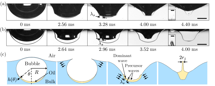
Figure 1 (a,b) shows the high-speed images for the bursting dynamics of oil-coated bubbles with different oil volume fractions while keeping the same liquid combination. Here, represents the oil volume and represents the bubble radius. The capillary waves are initiated after the bubble cap film ruptures. The waves travel down the cavity with their crests moving in phase on both the air–oil and oil–water interfaces, sweeping the oil toward the nadir of the cavity. As the capillary waves encounter a thicker oil layer during their propagation, they split onto oil-air and oil-water interfaces. The capillary waves reach the cavity bottom more quickly at the oil-air interface with a shorter traveling distance than those at the oil–water interface. The capillary waves at the oil-air interface converge and form a truncated cone-shaped cavity within the oil layer, ultimately producing an upward oily jet by the curvature reversal of the cavity bottom. Such dynamics of jet formation is summarized in Figure 1 (c).
Characterizing the capillary wave propagation during bubble bursting is critical for describing the jet dynamics [29, 23, 28]. Within the train of capillary waves, we denote the last and most energetic capillary wave as the dominant wave. Meanwhile, the capillary waves preceding the dominant wave, which travel faster with shorter wavelengths, are referred to as precursor waves. Specifically, the eminent wave closest to the dominant wave is considered as an indicator for wave damping due to its longest wavelength among the precursor waves, and we denote this capillary wave as the secondary wave with wavelength . For bubbles in a high-viscosity bulk liquid and coated by a thinner layer of low-viscosity oil (Fig. 1(a)), we observe that the cavity bottom is relatively smooth and flat with weaker precursor waves before the dominant wave converges. It suggests that the damping of the precursor waves is stronger, and therefore, the cavity collapse approaches the singular limit for a smaller jet radius [29, 23]. Consistently, a thin jet is observed (inset of Fig. 1(a)). In comparison, the precursor waves are more prominent and shorter in wavelength with a thicker layer of low-viscosity oil as shown in Fig. 1(b). The significant perturbations from the stronger precursor waves produce a larger . In our experiments, we note that this change in wave damping and jet size in the case of noticeably differs from the cases of , where an increase in enhances viscous damping and results in a smaller . The above observations demonstrate that the compound interface fundamentally alters jetting dynamics by modulating capillary wave damping, which necessitates careful characterization and interpretation.
Damping of capillary waves
The jetting dynamics of bare bubble bursting at an air-liquid interface is determined by two dimensionless numbers: Ohnesorge number and Bond number , where and are the surface tension, density, and viscosity of the liquid, respectively. The Bond number, which compares the gravity and capillary effects, is sufficiently small in our experiments, and therefore the gravity effect is negligible [11]. Therefore, the Ohnesorge number (comparing the inertio–capillary to inertio–viscous timescales) controls the jet dynamics. Here, represents the inertio-capillary timescale, and represents the inertio–viscous timescale. Since the amplitude damping of capillary waves controls the ejection of bubble bursting jets [29], can also be interpreted as a description for the progressive damping of the precursor waves during the bubble cavity collapse. The viscous damping rate for the amplitude of a capillary wave with wavelength at a free liquid surface can be estimated as . Here, represents the kinematic viscosity, and represents the wavenumber. Given that in bubble bursting, . Additionally, the cavity collapse occurs on a timescale of , as the time for the capillary waves to reach the bottom of the cavity . Consequently, the total viscous damping of the precursor waves is characterized by . Essentially, a higher indicates stronger damping of the precursor waves during the cavity collapse, sheltering the energy focusing of the dominant wave from the perturbation of the precursor waves, and finally resulting in thinner and faster jets [29, 11, 12, 23].
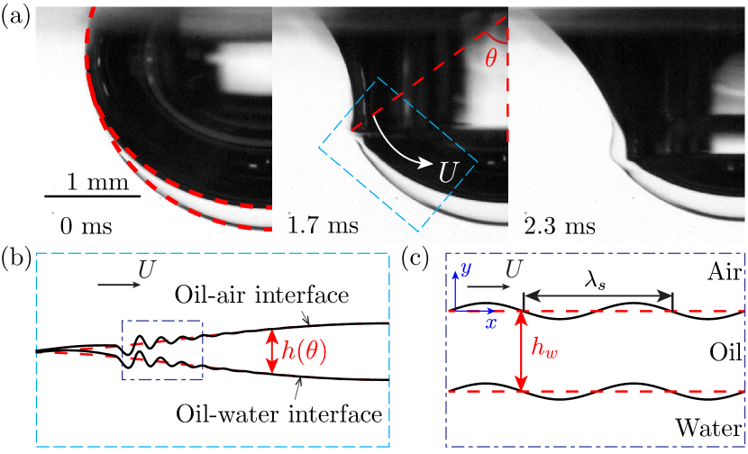
For an oil-coated bubble, however, the damping of capillary waves is influenced by the multiphase compound interface (Fig. 2(a)). Considering a static oil-coated bubble at the water surface, the oil layer is thicker near the bubble bottom due to the balance between surface tension and gravity. The capillary waves encounter an oil layer with an increasing thickness as they propagate towards the cavity bottom with the polar angle decreasing, as shown in the schematic of Fig. 2(b). Therefore, the above-mentioned capillary wave analysis for bare bubbles, which considers only the bulk liquid properties, requires careful revision for the compound bubbles. During capillary wave propagation, the energy dissipation arises from the viscous resistance to motions within both the oil layer and the bulk liquid. In particular, the damping of precursor capillary waves is time-dependent because of the non-uniform oil layer thickness. As the wave propagates into a thicker oil layer, the oil layer essentially contributes more to the total dissipation. This is in contrast to the constant damping rate estimated for the clean interface in the case of bare bubble bursting, which motivates us to furnish the capillary wave model to account for the difference between the compound and clean interfaces.
We aim to propose a minimal capillary wave model to describe this time-dependent capillary wave damping considering the following conditions and assumptions. In our experiments, the typical wavelength mm is an order of magnitude smaller than the capillary length , so the contribution of gravity becomes negligible [30]. Additionally, the surface curvature effect of the bubble radius is negligible since [30]. Therefore, we apply a 2D planar wave model to characterize the capillary waves on the cavity surface. The non-linear effects from the viscosity are considered negligible as our wavelength is much larger than the interfacial boundary layer thickness mm [31, 32]. Here, represents the oscillation frequency of the wave. Furthermore, the change in oil layer thickness within a wave period is insignificant considering and , allowing us to model a linear, periodic 2D capillary wave with a local oil layer thickness experienced by the precursor waves as shown in Fig. 2(c).
Following the above assumptions, the capillary wave motion in both phases satisfies the linearized Navier-Stokes equation for Newtonian liquids as
| (1) |
Here, represents pressure, and is a 2D periodic velocity field of
| (2) |
The subscript indicates that Eqs. (1,2) apply to the motion within the domain of both water () and oil (). represents the velocity dependence in the direction, and is the complex angular frequency of the wave. In addition to the free surface boundary conditions at , the boundary conditions of velocity continuity and stress balance are imposed at the water-oil interface at (see SI Appendix, section 1). The real part of corresponds to the oscillation frequency , and the imaginary part corresponds to the damping rate . is determined based on specified boundary conditions. is then solved (see SI Appendix, section 2) when the oil thickness and wavelength are given, which will be characterized in the next section.
Capillary wave modeling
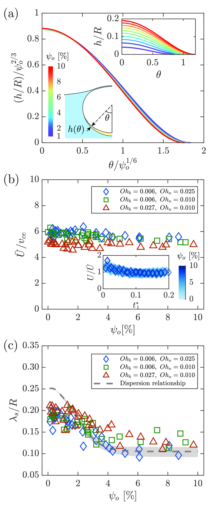
Oil layer thickness profile. To determine the oil layer thickness for the wave damping model, we calculate its initial distribution at the cavity surface of compound bubbles. The oil-coated bubble shape calculated using the Young-Laplace equations [33, 28] shows good agreement with experimental results as shown by the red dashed curves in Fig. 2(a). The inset of Fig. 3(a) illustrates the dimensionless oil layer thickness at the static bubble cavity surface for different oil fractions. We note that the oil layer thickness obeys the scaling relations of and .
Next, we obtain from the initial shape of the oil layer and the wave velocity. With the predicted oil layer distribution, we determine the local oil thickness encountered by the capillary wave based on the propagation speed of the waves. We measure the average wave velocity for selected cases by tracking the position of the dominant wave trough when , as shown in Fig. 3(b). For different oil Ohnesorge numbers and bulk Ohnesorge numbers , the dimensionless average wave velocity remains a nearly constant value of regardless of the oil fraction . Here, the effective capillary velocity is defined as . Such a constant wave velocity enables us to convert the spatial distribution of into the time dependency of for our further calculation of a varying damping rate.
Wavelength of secondary wave. To obtain for solving , the wave dispersion relationship must be considered since capillary waves traveling at a constant velocity should adopt fixed wavelengths determined by the dispersion relationship [34]. Considering , the dispersion relationship of the capillary waves can be described solely by the irrotational motion of the wave [35, 31]. The irrotational analysis of the capillary wave model yields two analytical solutions for wave dispersion, corresponding to the sinuous (barotropic) and varicose (baroclinic) modes documented in the literature [36, 37] (see SI Appendix, section 3). Because the wave motion at the compound interface is initiated in phase (Figs. 1(a) and 2(a)), we focus on the sinuous mode which obeys the dispersion law of
| (3) |
where
Here, is the phase speed of the sinuous mode, , and . Substituting into Eq. (3), the wavelength is uniquely determined for each .
The wavelength obtained from Eq. (3) shows how the oil layer thickness influences the precursor wave. Two limiting cases of and are recovered for the secondary wavelength for oil-coated bubble bursting using from the wave dispersion relation at a bare surface. When , the oil-air and oil-water interfaces oscillate synchronously at the water surface with and . The wavelength from Eq. (3) gives and , consistent with previous theoretical results [36] (see SI Appendix, section 3) and the wavelengths of the secondary wave observed for bare bubble bursting [38]. In contrast, when , the capillary waves on the two interfaces are spatially separated as shown in Fig. 1(b). Thus, the capillary waves at the top interface effectively travel in a deep layer of oil with and , resulting in . In Fig. 3(c), the wavelengths calculated using Eq. (3) with experimental parameters (see SI Appendix, section 5) are compared against experimental measurements at . The theoretical predictions capture the experimental trend of wavelength variation with the oil fraction, which are also consistent with the above two limiting cases. The modified dispersion relationship enables us to estimate for any given , which allows us to further solve for the instantaneous damping rates of the capillary waves.
for cumulative damping of precursor waves. The evolution of the instantaneous damping rate determines the cumulative damping of the capillary wave along the cavity surface. During the propagation of capillary waves, their energy attenuates due to viscous dissipation. Since the dissipation of the total energy of the capillary wave follows [30, 39]
| (4) |
the logarithmic damping on the wave energy from the initial energy to the final energy , representing a cumulative damping effect, can be expressed as [40, 29]
| (5) |
For bare bubbles where is a constant, the logarithmic damping simplifies to , which connects to the cumulative damping effect. We thus define the revised Ohnesorge number for oil-coated bubbles where varies with time as
| (6) |
where the coefficient (see SI Appendix, section 4). Notably, the revised Ohnesorge number accounts for the viscous damping introduced by a non-uniform oil layer in oil-coated bubble bursting.
Predicting jet size with revised Ohnesorge number
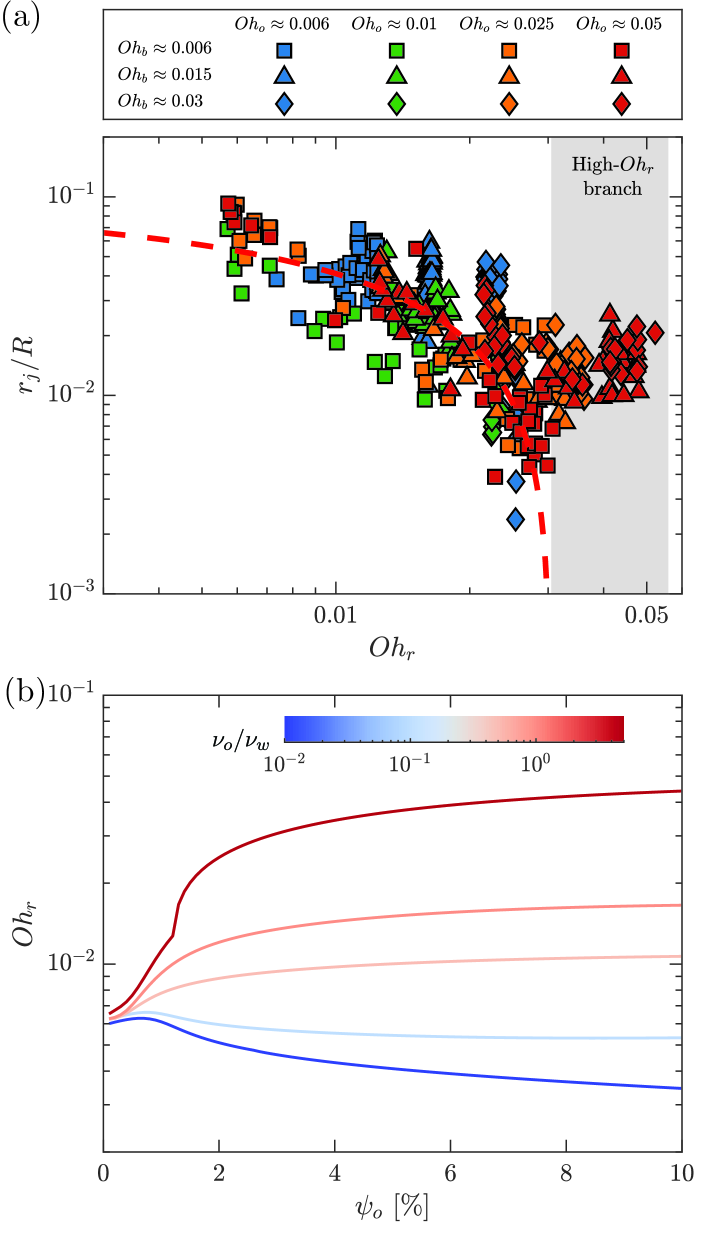
Figure 4(a) shows the dimensionless jet radius as a function of the proposed . The jet radius decreases as the revised Ohnesorge number increases, showing that a smaller jet radius is expected with stronger wave dissipation represented by higher . Considering the scaling relation of versus for bare bubble bursting [41], we propose a modified scaling relation by substituting with for a compound multiphase bubble as follows:
| (7) |
For our experiments covering a wide range of bulk Ohnesorge numbers from 0.006 to 0.03 and oil Ohnesorge numbers from 0.006 to 0.05, the proposed scaling law reasonably well captures the experimentally observed jet radii spanning two orders of magnitude. The consistency between the experimental results and the scaling law indicates that effectively characterizes the influence of the compound layer on the jet radius. In addition, we note the scaling law only holds for Ohnesorge numbers below a critical [13, 41], beyond which the viscous effect limits the minimum jet radius during its growth as found in bare bubble bursting[12, 42].
Figure 4 (b) shows the revised Ohnesorge number as a function of different oil fractions with the same and varying kinematic viscosity ratios. Notably, when the oil viscosity is greater than or comparable to the water viscosity ( or ), increases with increasing oil fraction, indicating stronger damping as rises. In contrast, when the oil viscosity is significantly lower than the water viscosity ( or ), our model predicts that decreases with . To understand how the trend depends on the kinematic viscosity ratio, we express the Ohnesorge number as
| (8) |
since and . Considering represents the characteristic boundary layer thickness [43, 44, 23], can indicate the ratio between the boundary layer length scale and the secondary wavelength. For oil-coated bubble bursting, the oil layer thus influences by altering both the boundary layer thickness and the wavelength of the precursor waves. Increasing decreases from to as shown in Fig. 3(c). Meanwhile, the characteristic depends on the kinematic viscosities of both liquids at the compound interface, with oil viscosity contributing more as increases. When , increases with since a thicker oil layer with a higher oil kinematic viscosity allows a larger depth of penetration for viscous diffusion. Therefore, the increase in and the decrease in collectively contribute to an increase in as increases. However, when , decreases with increasing given smaller . When the decrease in outweighs the decrease of and thus decreases , the precursor waves essentially experience less damping by the time they reach the cavity bottom. The undamped perturbations from the precursor waves disrupt the focusing of the dominant waves and cause the jet size to increase. While our revised Ohnesorge number describes the jet radius well, the jet velocity will require further discussion. For the same , we observe that the jet velocity decreases with . The phenomenon may originate from the additional viscous stresses due to the multiphase flow during jet growth, which is beyond the scope of the current work.
We believe that the introduction of provides a fundamental framework to characterize how a structurally compound liquid-bubble interface influences the microscale fluid mechanics associated with bubble dynamics. Specifically, bubbles are often contaminated by surface-active substances such as surfactants, proteins, or particulates, which are prevalent in various natural and industrial settings [45, 15, 46, 47, 48]. Such contaminated interfaces may exhibit diverse stress responses to deformation, including Marangoni stress, surface viscosity and surface elasticity. Our methodology based on capillary wave theory may be broadened to include a wide variety of these systems, offering a robust approach to characterizing the resulting alterations in jetting dynamics.
Conclusions
In this study, we have investigated the influence of an immiscible compound coating on the size of bubble bursting jets. We identified that the damping of capillary waves during their propagation plays a critical role in determining jet characteristics. As the oil fraction increases, the impact of the oil-water interface on precursor waves gradually diminishes as they propagate to the cavity bottom, while the oil viscosity becomes increasingly significant, leading to a reduction in the characteristic wavelength. To account for these effects, we developed a linearized wave model to calculate the damping rate of capillary waves. A revised Ohnesorge number that incorporates the influence of the compound interface on the capillary wave damping was proposed, which effectively collapses the jet size data across a wide range of oil coating fractions and viscosity ratios. Our scaling relation for the jet size offers model constraints and engineering insights for the ejected contaminant-laden drop size, which can be applied to evaluate bubble-mediated airborne flux of pollutants from multiple sources including ocean or wastewater treatment. In addition, our current study focuses on bubbles coated with a Newtonian fluid layer, establishing a benchmark framework for future work that investigates compound bubbles coated with rheologically complex fluids. Given the prevalence of complex biocontaminants, such as extracellular polymeric substances produced through microbial secretion, metabolism, and lysis in natural and engineered systems [49, 50], understanding the bursting dynamics of bubbles coated with a non-Newtonian compound layer would be of significant fundamental interest and hold broader implications for bubble-mediated marine chemistry and biology as well as environmental science.
Acknowledgements. Z.Y. and J.F. acknowledge partial support by the National Science Foundation (NSF) under grant No. CBET 2426809 and the research support award RB24105 from Campus Research Board at University of Illinois at Urbana-Champaign. We also thank Bingqiang Ji for fruitful discussions about the experiments.
I Methods
I.1 Materials
Deionized water (electrical resistivity = 18.2 Mcm at C) is produced by a laboratory water purification system (Smart2Pure 3 UV/UF, Thermo Fisher Scientific). Silicon oils including octamethyltrisiloxane ( = 1 cSt), dodecamethylpentasiloxane ( = 2 cSt) and others ( = 5, 10 cSt) were purchased from Sigma-Aldrich and used as received. Glycerin was purchased from Fisher Chemical. The surface tensions were measured using the pendant drop method [51], including the surface tension between the oil and air (), the glycerin solution and air (), and the oil and glycerin solution () (see SI Appendix, section 5).
I.2 Experimental setup
The oil-coated bubbles were generated by a coaxial orifice system plugged in an acrylic container, a setup described in detail in our previous work [52, 28]. The equilibrium radius of the released compound bubble (gas+oil) in our experiments was determined to be mm. After the bubbles rested at the water surface, we used two high-speed cameras (FASTCAM Mini AX200, Photron) to synchronously record the top and bottom side views of the bubble cavity collapse and jet formation, at a frame rate of 6400-20000 frames per second and a magnification of 1-4. Two LED panels (Phlox 100100 HSC; Phlox 200200 HSC) were used to illuminate the bubble bursting for the two cameras separately. The obtained images were post-processed with Fiji/ImageJ and MATLAB.
References
- [1] J. C. Bird, R. De Ruiter, L. Courbin, and H. A. Stone, Daughter bubble cascades produced by folding of ruptured thin films, Nature 465, 759 (2010).
- [2] J. Feng, M. Roché, D. Vigolo, L. N. Arnaudov, S. D. Stoyanov, T. D. Gurkov, G. G. Tsutsumanova, and H. A. Stone, Nanoemulsions obtained via bubble-bursting at a compound interface, Nat. Phys. 10, 606 (2014).
- [3] F. Veron, Ocean spray, Annu. Rev. Fluid Mech. 47, 507 (2015).
- [4] L. Deike, Mass transfer at the ocean–atmosphere interface: The role of wave breaking, droplets, and bubbles, Annu. Rev. Fluid Mech. 54, 191 (2022).
- [5] L. Bourouiba, Fluid dynamics of respiratory infectious diseases, Annu. Rev. Biomed. Eng. 23, 547 (2021).
- [6] D. Murphy, B. Gemmell, L. Vaccari, C. Li, H. Bacosa, M. Evans, C. Gemmell, T. Harvey, M. Jalali, and T. H. Niepa, An in-depth survey of the oil spill literature since 1968: Long term trends and changes since Deepwater Horizon, Mar. Pollut. Bull. 113, 371 (2016).
- [7] M. Trainic, J. M. Flores, I. Pinkas, M. L. Pedrotti, F. Lombard, G. Bourdin, G. Gorsky, E. Boss, Y. Rudich, A. Vardi, et al., Airborne microplastic particles detected in the remote marine atmosphere, Commun. Earth Environ. 1, 1 (2020).
- [8] X. Wang, G. B. Deane, K. A. Moore, O. S. Ryder, M. D. Stokes, C. M. Beall, D. B. Collins, M. V. Santander, S. M. Burrows, C. M. Sultana, et al., The role of jet and film drops in controlling the mixing state of submicron sea spray aerosol particles, Proc. Natl. Acad. Sci. 114, 6978 (2017).
- [9] T. W. Wilson, L. A. Ladino, P. A. Alpert, M. N. Breckels, I. M. Brooks, J. Browse, S. M. Burrows, K. S. Carslaw, J. A. Huffman, C. Judd, et al., A marine biogenic source of atmospheric ice-nucleating particles, Nature 525, 234 (2015).
- [10] L. Bourouiba, The fluid dynamics of disease transmission, Annu. Rev. Fluid Mech. 53, 473 (2020).
- [11] L. Deike, E. Ghabache, G. Liger-Belair, A. K. Das, S. Zaleski, S. Popinet, and T. Séon, Dynamics of jets produced by bursting bubbles, Phys. Rev. Fluids 3, 013603 (2018).
- [12] C. F. Brasz, C. T. Bartlett, P. L. Walls, E. G. Flynn, Y. E. Yu, and J. C. Bird, Minimum size for the top jet drop from a bursting bubble, Phys. Rev. Fluids 3, 074001 (2018).
- [13] A. M. Gañán-Calvo and J. M. López-Herrera, On the physics of transient ejection from bubble bursting, J. Fluid Mech. 929, A12 (2021).
- [14] J. M. Gordillo and F. J. Blanco-Rodríguez, Theory of the jets ejected after the inertial collapse of cavities with applications to bubble bursting jets, Phys. Rev. Fluids 8, 073606 (2023).
- [15] P. L. Walls, J. C. Bird, and L. Bourouiba, Moving with bubbles: a review of the interactions between bubbles and the microorganisms that surround them, Am. Zool. 54, 1014 (2014).
- [16] B. Ji, A. Singh, and J. Feng, Water-to-Air Transfer of Nano/Microsized Particulates: Enrichment Effect in Bubble Bursting Jet Drops, Nano Lett. 22, (2022).
- [17] C. Johansen, A. C. Todd, and I. R. MacDonald, Time series video analysis of bubble release processes at natural hydrocarbon seeps in the northern Gulf of Mexico, Mar. Pet. Geol. 82, 21 (2017).
- [18] F. S. Ehrenhauser, P. Avij, X. Shu, V. Dugas, I. Woodson, T. Liyana-Arachchi, Z. Zhang, F. R. Hung, and K. T. Valsaraj, Bubble bursting as an aerosol generation mechanism during an oil spill in the deep-sea environment: laboratory experimental demonstration of the transport pathway, Environ. Sci.: Processes Impacts 16, 65 (2014).
- [19] F. Zhou, L. Wang, Z. Xu, Q. Liu, M. Deng, and R. Chi, Application of reactive oily bubbles to bastnaesite flotation, Miner. Eng. 64, 139 (2014).
- [20] L. Su, Z. Xu, and J. Masliyah, Role of oily bubbles in enhancing bitumen flotation, Miner. Eng. 19, 641 (2006).
- [21] S. H. Behrens, Oil-coated bubbles in particle suspensions, capillary foams, and related opportunities in colloidal multiphase systems, Curr. Opin. Colloid Interface Sci. 50, 101384 (2020).
- [22] C. W. Visser, D. N. Amato, J. Mueller, and J. A. Lewis, Architected polymer foams via direct bubble writing, Adv. Mater. 31, 1904668 (2019).
- [23] J. Gordillo and J. Rodríguez-Rodríguez, Capillary waves control the ejection of bubble bursting jets, J. Fluid Mech. 867, 556 (2019).
- [24] J. Pierre, M. Poujol, and T. Séon, Influence of surfactant concentration on drop production by bubble bursting, Phys. Rev. Fluids 7, 073602 (2022).
- [25] E. J. Vega and J. M. Montanero, Influence of a surfactant on bubble bursting, Exp. Therm. Fluid Sci. 151, 111097 (2024).
- [26] B. Ji, Z. Yang, Z. Wang, R. H. Ewoldt, and J. Feng, Secondary bubble entrainment via primary bubble bursting at a viscoelastic surface, Phys. Rev. Lett. 131, 104002 (2023).
- [27] Z. Yang, S. Barbhai, B. Ji, and J. Feng, Effect of surface viscoelasticity on top jet drops produced by bursting bubbles, Soft Matter 20, 4868 (2024).
- [28] Z. Yang, B. Ji, J. T. Ault, and J. Feng, Enhanced singular jet formation in oil-coated bubble bursting, Nat. Phys. 19, 884 (2023).
- [29] S. Krishnan, E. J. Hopfinger, and B. A. Puthenveettil, On the scaling of jetting from bubble collapse at a liquid surface, J. Fluid Mech. 822, 791 (2017).
- [30] H. Lamb, Hydrodynamics, 4th Edn (University Press, Cambridge, 1916).
- [31] F. Denner, Frequency dispersion of small-amplitude capillary waves in viscous fluids, Phys. Rev. E 94, 023110 (2016).
- [32] L. Shen, F. Denner, N. Morgan, B. van Wachem, and D. Dini, Marangoni effect on small-amplitude capillary waves in viscous fluids, Phys. Rev. E 96, 053110 (2017).
- [33] H. Lhuissier and E. Villermaux, Bursting bubble aerosols, J. Fluid Mech. 696, 5 (2012).
- [34] M. J. Lighthill and J. Lighthill, Waves in fluids (University Press, Cambridge, 2001).
- [35] U.-S. Jeng, L. Esibov, L. Crow, and A. Steyerl, Viscosity effect on capillary waves at liquid interfaces, J. Phys. Condens. Matter 10, 4955 (1998).
- [36] G. K. Rajan, A three-fluid model for the dissipation of interfacial capillary-gravity waves, Phys. Fluids 32, 122121 (2020).
- [37] P. S. Stewart, J. Feng, L. S. Kimpton, I. M. Griffiths, and H. A. Stone, Stability of a bi-layer free film: simultaneous or individual rupture events?, J. Fluid Mech. 777, 27 (2015).
- [38] Z. Yang, B. Ji, and J. Feng, Daughter oil droplet entrainment by oil-coated bubble bursting, J. Fluid Mech. 977, A10 (2023).
- [39] S. Ermakov and G. Khazanov, Resonance damping of gravity–capillary waves on water covered with a visco-elastic film of finite thickness: A reappraisal, Phys. Fluids 34, 092107 (2022).
- [40] M. S. Longuet-Higgins, Viscous dissipation in steep capillary–gravity waves, J. Fluid Mech. 344, 271 (1997).
- [41] F. J. Blanco-Rodríguez and J. Gordillo, On the jets produced by drops impacting a deep liquid pool and by bursting bubbles, J. Fluid Mech. 916, A37 (2021).
- [42] F. J. Blanco-Rodríguez and J. Gordillo, On the sea spray aerosol originated from bubble bursting jets, J. Fluid Mech. 886, R2 (2020).
- [43] G. K. Batchelor, An introduction to fluid dynamics (Cambridge University Press, New York, 2000).
- [44] X. Tang, A. Saha, C. Sun, and C. K. Law, Spreading and oscillation dynamics of drop impacting liquid film, J. Fluid Mech. 881, 859 (2019).
- [45] O. Wurl, E. Wurl, L. Miller, K. Johnson, and S. Vagle, Formation and global distribution of sea-surface microlayers, Biogeosciences 8, 121 (2011).
- [46] P. L. Walls and J. C. Bird, Enriching particles on a bubble through drainage: Measuring and modeling the concentration of microbial particles in a bubble film at rupture, Elementa 5, 34 (2017).
- [47] S. Poulain and L. Bourouiba, Biosurfactants change the thinning of contaminated bubbles at bacteria-laden water interfaces, Phys. Rev. Lett. 121, 204502 (2018).
- [48] B. Néel and L. Deike, Collective bursting of free-surface bubbles, and the role of surface contamination, J. Fluid Mech. 917, A46 (2021).
- [49] T. More, J. S. S. Yadav, S. Yan, R. D. Tyagi, and R. Y. Surampalli, Extracellular polymeric substances of bacteria and their potential environmental applications, J. Environ. Manag. 144, 1 (2014).
- [50] S. Poulain, E. Villermaux, and L. Bourouiba, Ageing and burst of surface bubbles, J. Fluid Mech. 851, 636 (2018).
- [51] B. Song and J. Springer, Determination of interfacial tension from the profile of a pendant drop using computer-aided image processing: 2. Experimental, J. Colloid Interface Sci. 184, 77 (1996).
- [52] B. Ji, Z. Yang, and J. Feng, Oil-coated bubble formation from submerged coaxial orifices, Phys. Rev. Fluids 6, 033602 (2021).