Scintillation and Timing Performance of a 3at% Yttrium-Doped Barium Fluoride Crystal
Abstract
We report the scintillation and timing performance of a new developed large size barium fluoride crystal doped with 3at% yttrium () to enhance the application for high time resolution. This doping effectively suppresses the slow scintillation component while maintaining most of the fast component, as confirmed by X-ray excited luminescence measurements. The crystal demonstrated a transmittance of near 90% in the visible spectrum and a light response uniformity parameter of when coupled with the tail end. The actual yttrium content varied from 2.1at% near the seed end to 3.7at% at the tail end. The assembled large detector with silicon photomultipliers exhibited a time resolution of using constant fraction discrimination method in a cosmic ray test and using a low fixed threshold method in a beam test at Shanghai Synchrotron Radiation Facility with an electron beam. These results indicate the significant potential of crystal for various applications, such as detectors for particle physics and nuclear physics.
1 Introduction
Inorganic scintillators play a crucial role in the development of electromagnetic calorimeters (ECALs) utilized in high-energy physics (HEP) and nuclear physics experiments. Additionally, precise timing is essential for spectrometers, notably the Time-of-Flight (TOF) detector used in relativistic heavy ion collider experiments [1]. The next generation of HEP experiments—including the Circular Electron Positron Collider, the Super Tau-Charm Facility, and the upgrade of the Belle II experiment—demands ultra-fast scintillators capable of meeting increasingly stringent time resolution requirements [3, 2, 4, 5]. The ECAL designs for some projects necessitate scintillators with a timing capability of about and robust radiation tolerance [6]. Meanwhile, ultra-high-frequency radiation imaging and detection are also critical for probing internal nuclear reaction processes and assessing the structural integrity of materials [7]. Facilities utilizing XFELs, such as LCLS, SACLA, and SwissFEL, have developed ultra-fast imaging technologies that significantly enhance their experimental timing capabilities [8, 9].
Among various scintillating materials, barium fluoride () has emerged as a promising candidate due to its remarkable properties. Characterized by an ultra-fast cross-luminescence component with a decay time of approximately , demonstrates superior timing capabilities [10]. also stands out as a cost-effective scintillator with great potential for mass-producing large crystals. Consequently, has been adopted as the bottom-line scintillator of choice for Mu2e-II ECAL and is uniquely positioned to fulfill the stringent requirements for sub-nanosecond time resolution in Project X [11].
The implementation of TOF technology requires scintillators with an exceptional time resolution of less than , a criterion where the ultra-fast inorganic scintillator excels [12]. With advancements in quantum efficiency of photon detection from silicon photomultipliers (SiPMs), detector can achieve a time resolution as low as with crystals, highlighting its immense potential for ultra-fast timing applications in TOF systems [13]. However, this time-resolved result is measured when the size of the crystal is relatively small, and newer detectors often require large size inorganic scintillator crystals [14]. At the same time, the CMS upgrade plan to solve the problem of signal accumulation that may occur later, the LYSO:Ce crystal of is selected [15, 16]. This detector will measure tens of picoseconds of time in its barrel, but the crystal size is not large compared to the organic scintillators used for TOF. There is potential for using large size crystals for timing detectors in large future HEP facilitates.
However, also presents a slow component featuring emission peaks in the range of and a decay time of about , which provides a light output that is 4 to 5 times greater than that of the fast component [17, 18]. This dual-component behavior poses significant challenges, particularly in high-counting-rate scenarios, as it can lead to substantial signal pile-up and also deteriorates its timing performance [19, 20]. This issue is critical for future intensity frontier HEP experiments using intense particle beams that require ultra-fast precise radiation measurements. Incorporating (yttrium) into the crystal structure, denoted as , can effectively suppress the slow scintillation component while preserving the desirable characteristics of the ultra-fast scintillation [21]. In 2019, to meet the demands for hard X-ray imaging at the Matter-Radiation Interactions in Extreme (MaRIE) free-electron laser facility, Chen Hu et al. proposed the use of crystals for ultra-fast, full-absorption scintillator-based imaging [12].
Using the Bridgman method, we grew and fabricated a single crystal boule with a doping concentration of 3at% (atomic percentage of cationic atoms) yttrium and a length of . We found that the 3at% yttrium concentration is the optimization to suppress the slow component and ensure the fast component’s light output. A comprehensive analysis of this scintillator’s optical and pertinent characteristics was conducted, followed by determining its time resolution within the context of cosmic rays and high-energy electron beams in a TOF setup. In this study, we report the application of large for high-energy experiments for particle physics and nuclear physics and measure the related properties first.
2 Scintillation characteristics of
High-purity raw materials, (4N) and (5N) were accurately weighed according to a molar ratio of , and subsequently homogenized and placed into graphite crucibles for vacuum Bridgman method within a growth rate of . Figure 1(a) shows the relative position of all samples used in the experiments in as-grown boule before machining. The samples surrounding the -long crystal were divided into equal segments from the seed end to the tail end. Samples P1-P10 were ground into powder for inductively coupled plasma atomic emission spectroscopy (ICP-AES) analysis to determine the effective concentration distribution of yttrium within the crystal. Additionally, samples A1-A10 with a dimension of , were cut and fabricated for X-ray excited luminescence (XEL) testing.
As shown in Fig. 1(b), the effective concentration of yttrium increases gradually from 2.12at% at the seed end to 3.66at% at the tail end. The uniformity of doping within the crystal material is typically assessed by the effective segregation coefficient, , which be calculated by solving the equation:
| (2.1) |
where and are the dopant concentrations in the crystal and the melt, respectively, and is the solidification fraction of the melt, refers to the volume ratio of the part solidified into the crystal to the whole ingot during the crystal growth [22]. The of the crystal was determined to be . Compared with La, which has a in crystal, the measured here indicates that more uniform yttrium doping has been achieved in crystal.
We conducted separate measurements of the transmittance spectra along the lateral direction with a optical path at the midpoint of the -long crystal and along the growth direction with a optical path, within the range of to . Figure 2(a) shows an 80% lateral transmittance at and maintains a transmittance close to 90% within the visible spectrum. Compared to the previous -long crystal doped with 1at% yttrium reported in 2018, the optical quality has improved without significant absorption at [12]. However, the crystal exhibits yet to be improved transmittance along the growth direction, primarily due to the quality variations at the ends caused by an unstable growth process. Consequently, there is considerable scope for further enhancement in the optical quality of through an optimized growth process.

Different concentrations of crystals exhibit distinct suppression levels of the slow scintillation component. From the former XEL spectra study, there are two prominent peaks in the range of to , corresponding to the fast CVL component at and the slow STE component at [12, 23]. Figure 2(b) presents the results of the XEL spectral analysis conducted on the crystals, with measurements taken from the seed end (A1) to the tail end (A10) of the A series samples, in comparison to a pure sample [UA in Fig. 2(b)]. The original 3at% yttrium doping significantly reduces the intensity of the slow component’s emission, reducing it to approximately 20% of the intensity observed in pure crystals. Figure 2(b) also emerges a noticeable trend. As the yttrium content increases from 2.12at% near the seed end to 3.66 at% at the tail end, the luminescence intensity of the slow component consistently declines. The suppression effects on the slow component due to yttrium segregation are slightly more pronounced from the seed end to the tail end, with variations not exceeding 5%. Conversely, the luminescence intensity of the fast component exhibits only marginal changes relative to the intensity of the pure crystal, indicating a selective impact of yttrium on the crystal’s radioluminescence properties.
We conducted light response uniformity (LRU) testing of the crystal using a collimated source to explore the relationship between the normalized gate relative light output and the distance from the coupling surface to the radiation source [24]. This investigation coupled the Hamamatsu R2059 photomultiplier tube (PMT) at the crystal’s seed or tail end to form a single-end readout mode. To enhance the light collection efficiency, the coupling surface was treated with Dow Corning PMX-200 silicone oil, and the other surface was wrapped with a single layer of Tyvek. The collimated source emitted gamma rays at equidistant points along the length of the crystal to measure light output at various excitation positions. The single-end readout experimental setup was established to evaluate the LRU performance of the crystal when excited by gamma rays, as depicted in Fig. 3(a). The absolute light output is defined as
| (2.2) |
where represents the channel of the full energy peak in pulse height spectra, is the channel of the single photoelectron peak in pulse height spectra under the same test conditions, and denotes the gamma-ray energy from the source equal to . The emission-weighted quantum efficiency of the scintillator when coupled with the R2059 PMT was calculated to be 21.6%.
The deviation parameter for LRU, denoted as , is defined by the solving the equation
| (2.3) |
where is the source position from the coupling end, and is the fitted value of the light output at the midpoint of the crystal. Generally, an absolute value of less than 5% is considered desirable for scintillation crystals used in calorimetry applications.
The fitting results from the LRU experiments, presented in Figs. 3(b) and 3(c), reveal that when the crystal was coupled at the seed end, the corresponding value was . In contrast, coupling at the tail end resulted in a value of . Furthermore, the average light output measured from the seed and tail ends was found to be and , respectively.
Although the average light output of the two ends is nearly equal, the LRU performance shows an obvious difference. The LRU performance, when coupled from the seed end, is significantly compromised due to defects in the seed region and an increase in yttrium concentration. The poor transmittance leads to increased scattering light loss, adversely affecting overall LRU performance, while the elevated yttrium concentration contributes to a similar negative trend. In contrast, coupling from the tail end exhibited superior LRU performance, with a value within the acceptable range of less than 5%. This improvement can be attributed to a more favorable balance of light transmission loss and a decrease of light output by increasing the actual yttrium concentration when coupled from the tail end. These findings suggest that for long , coupling from the tail end could offer greater potential for applications.
Looking ahead, we anticipate that further advancements in growth conditions and increasing the optical transmittance of crystal will improve the LRU of the crystal, thereby enhancing its suitability for various experimental applications.
3 Timing performance of
Cosmic rays and an electron beam in the Shanghai Synchrotron Radiation Facility (SSRF) were utilized to evaluate the time resolution of a detector prototype built with the crystal and a SiPM array, thereby simulating practical scenarios encountered in various applications [25, 26, 27]. Figure 4(a) illustrates the experimental setup employed for measuring time resolution. The trigger system consisted of two plastic scintillators at the top and bottom of the detector. Waveform acquisition was performed using the CAEN digitizer DT5742, boasting a sampling rate of 5 GS/ and a bandwidth of , delivering excellent performance in high-speed signal acquisition applications. Initially, the two signals from the plastic scintillators were coincident, and the logic signals were then routed into TR0 of the DT5742 to serve as the system’s trigger.
Figure 4(b) shows the assembled detector. All surfaces of the crystal were thoroughly polished. Except for the face coupled to the SiPM array, the crystal was wrapped in a single layer of Tyvek, followed by a layer of black insulating tape, to enhance light reflection at its surfaces. We selected the fourth-generation VUV-MPPC S13371-6050CQ-02, optimized for photon detection in the ultraviolet region, for the detector [28, 29]. The type of SiPM is particularly well-suited for detecting the luminescence emitted by crystals, especially the fast scintillation component that peaks around . The four VUV-MPPCs were connected in series to increase the sensitivity area for photon detection. The two plastic scintillators have a same dimension of . Each bar was coupled at one end of the cross section () to an array of four Hamamatsu S14160-6050 MPPCs using PMX-200 silicone oil. The scintillators were subsequently wrapped in aluminum foil and covered with insulating tape to prevent light leakage.
To get better time resolution, we had developed a novel high-speed preamplifier with a bandwidth of , a baseline noise of approximately , and a good time resolution better than [30]. Upon digitizing the waveform with the digitizer, the resulting data is processed offline on a computer. After analyzing the waveforms from DT5742, we extracted comprehensive data regarding the ADC values, Time-to-Digital Converter (TDC) measurements, baseline stability, and timing precision [32]. To accurately determine the arrival time of the signals, we fitted the rising edge of the waveform and then employ the constant fraction discrimination (CFD) method.
3.1 Cosmic ray test
As shown in Fig 4(a), the trigger time of the test system was calculated by averaging the times recorded by the two plastic scintillators: , where and are of the two scintillators. The time difference between the two plastic scintillators denoted as , was used to calculate the time resolution of the trigger system, represented as . The distribution of is shown in Fig. 5(a). By fitting this distribution with a Gaussian function, we obtained a standard deviation of , resulting in a time resolution of for the trigger system.
The time difference between the arrival time in the crystal () and the trigger system was given by , as shown in Fig. 5(b). Fitting to the distribution of with a Gaussian function, we obtained . Therefore, we obtained the time resolution of the detector to be . In this test, the energy level broadening of the two peaks was minimal, and background interference with the signal measurements was virtually nonexistent.
3.2 Electron beam test at SSRF
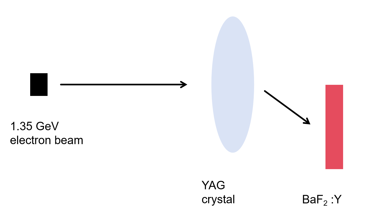
To measure the time resolution of the crystal and its corresponding photon detector for high-energy particles, we positioned the test system within a high-energy electron beam at the SSRF for comprehensive testing. As illustrated in Fig. 6, the energy of the electron beam was set to be . Due to the presence of a YAG crystal in the beamline for luminosity monitoring, we could not directly detect the electrons from the beamline but rather those scattered by the YAG crystal. After passing through the YAG crystal, the electrons did not experience significant energy loss, but they had an angular distribution.
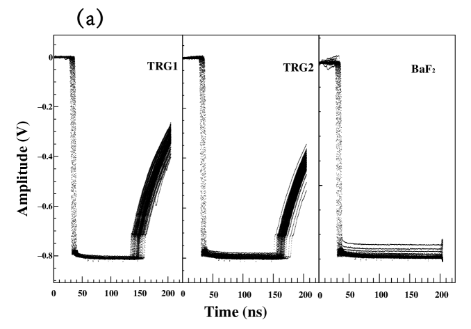
During the test, we encountered a significant issue related to the high energy deposited in the two scintillator triggers and the sample. Figure 7(a) illustrates the waveforms of the trigger system and the detector. The pulse heights consistently exceeded the dynamic range of the preamplifier [30], which rendered the CFD method inapplicable. As a result, we relied on timing measurements obtained from a fixed low threshold.
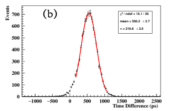
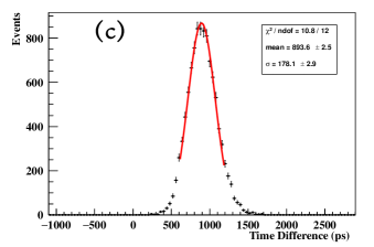
By analyzing the distributions presented in Fig. 7(b), we determined a standard deviation of , which corresponds to a time resolution of for this test. The distribution of between the detector and the trigger system is depicted in Fig. 7(c), where we obtained , leading to a time resolution of .
It is noteworthy that more accurate timing data and energy deposition measurements could be achieved with an enhanced preamplifier that offers a broader dynamic range.
4 Conclusion and Discussion
To promote the application of in HEP experiments within particle and nuclear physics, we grew a -long large crystal doped with 3at% yttrium. This doping effectively suppresses the slow scintillation component while preserving most of the fast component. XEL measurement results confirmed a consistent reduction in the slow scintillation component throughout the crystal, and ICP-AES indicated a relatively uniform effective yttrium concentration with . The crystal demonstrated an 80% lateral transmittance at and maintained a transmittance near 90% within the visible spectrum, reflecting its excellent optical quality. Additionally, the light response uniformity with a when coupled with the tail end underscores its suitability for future high-energy experiments applications.
Integrating the crystal with SiPMs yielded impressive timing resolutions in tests conducted with cosmic rays and high-energy electron beams. Utilizing the CFD method, we achieved a time resolution of for the detector when exposed to cosmic rays. We could not apply the CFD method in tests with a electron beam at the SSRF due to excessive deposited energy within the trigger system and the crystal. Instead, we obtained a time resolution of for the large detector using timing information from a low fixed threshold.
We anticipate that further optimization of a larger detector will yield even better time resolution. The promising performance of the crystal suggests its potential for applications in high-energy experiments. For the next generation of bulk detectors for HEP applications, we can further optimize the newer and better electronics for the time timing characteristics, also provide further optimization of doping elements, element ratio to improve the light yield of , optimize the growth process to improve the homogeneity of the crystal material to improve the time resolution further.
Acknowledgment
This work is partially supported by the National Key R&D Program of China under Contract Nos. 2022YFA1601903, and 2022YFB3503902; the National Natural Science Foundation of China under Contracts Nos. 12175041, 12025501; the Strategic Priority Research Program of the Chinese Academy of Sciences (XDA25030600); the opening fund of Key Laboratory of Rare Earths, Chinese Academy of Sciences.
References
- [1] J. H. Chen et al., Properties of the QCD matter: review of selected results from the relativistic heavy ion collider beam energy scan (RHIC BES) program, Nucl. Sci. Tech. 35 (2024) 214.
- [2] The CEPC Study Group, CEPC Conceptual Design Report: Volume 2 - Physics & Detector, arXiv:1811.10545v1.
- [3] The CEPC Study Group, CEPC Technical Design Report – Accelerator, arxiv:2312.14363.
- [4] M. Achasov et al., STCF conceptual design report (Volume 1): Physics & detector, Front. Phys. 19 (2022) 17401.
- [5] H. Aihara et al., The Belle II Detector Upgrades Framework Conceptual Design Report, arXiv:2406.19421.
- [6] X. Z. Yu et al., Production and test of sPHENIX W/SciFiber electromagnetic calorimeter blocks in China, Nucl. Sci. Tech. 35 (2024) 145.
- [7] H. K. Wu et al., Fudan multi-purpose active target time projection chamber (fMeta-TPC) for photonuclear reaction experiments, Nucl. Sci. Tech. 35 (2024) 200.
- [8] N. S. Huang et al., Features and futures of X-ray free-electron lasers, Innovation 2 (2021) 2.
- [9] T. A. White et al., Recent developments in CrystFEL, J. Appl. Crystallogr 49 (2016) 2.
- [10] R. Y. Zhu, Crystal Calorimeters in the Next Decade, Phys. Procedia 37 (2012) 372.
- [11] S. Miscetti, Design and status of the Mu2e experiment, EPJ Web of Conference 118 (2016) 01021.
- [12] C. Hu et al., Ultrafast inorganic scintillator-based front imager for Gigahertz Hard X-ray imaging, Nucl. Instrum. Methods A 940 (2019) 223-229.
- [13] S. Gundacker et al., Vacuum ultraviolet silicon photomultipliers applied to cross-luminescence detection for high-rate ultrafast timing applications, Phys. Med. Biol. 66 (2021) 11.
- [14] Y. D. Sheng et al., The large-scale modular BGO detection array (LAMBDA) design and test, Nucl. Sci. Tech. 35 (2024) 207.
- [15] N. Atanov et al., Development, construction and tests of the Mu2e electromagnetic calorimeter mechanical structures, JINST 17 (2022) C01007.
- [16] Daniele del Re for the CMS Collaboration, Precision Timing with the CMS MTD Barrel Timing Layer for HL-LHC, The Compact Muon Solenoid Experiment Conference Report (2021) .
- [17] P. Schotanus et al., Photoelectron production in BaF2-TMAE detectors, Nucl. Instrum. Methods A 259 (1987) 3.
- [18] M. R. Farukhi and C. F. Swinehart, Barium Fluorides as A Gamma-ray and Charged Particle Detector, IEEE Trans. Nucl. Sci. 18 (1971) 1.
- [19] C. L. Woody, P. W. Levy, and J. A. Kierstead, Slow component suppression and radiation damage in doped crystals, IEEE Trans. Nucl. Sci. 36 (1989) 1.
- [20] D. Visvikis et al., Performance characterisation of large area -TMAE detectors for use in a whole body clinical PET camera, Nucl. Instrum. Methods A 392 (1997) 1.
- [21] J. F. Chen et al., Slow Scintillation Suppression in Yttrium Doped Crystals, IEEE Trans. Nucl. Sci. 65 (2018) 8.
- [22] F. Yang et al., La- and La-/Ce- Doped Crystals for Future HEP Experiments at the Energy and Intensity Frontiers Part I, IEEE Trans. Nucl. Sci. 66 (2019) 1.
- [23] C. Hu et al., Development of Yttrium-Doped Crystals for Future HEP Experiments, IEEE Trans. Nucl. Sci. 66 (2019) 7.
- [24] L. Y. Yuan et al., High Light Response Uniformity in Industrial Growth of 600-mm-Long BGO Crystals for DArk Matter Particle Explorer, IEEE Trans. Nucl. Sci. 65 (2018) 7.
- [25] M. H. Jiang et al., Shanghai Synchrotron Radiation Facility, Chin. Sci. Bull. 54 (2009) 22.
- [26] W. Y. Cheng, K. Deng, and Y. S. Zeng, Development of an enhanced online tritium monitoring system using plastic scintillation fiber array, Nucl. Sci. Tech. 35 (2024) 10.
- [27] K. J. Chen et al., Simulation and test of the SLEGS TOF spectrometer at SSRF, Nucl. Sci. Tech. 34 (2023) 47.
- [28] T. Pershing et al., Performance of Hamamatsu VUV4 SiPMs for detecting liquid argon scintillation, JINST 17 (2022) 4.
- [29] F. Vachon et al., Measuring count rates free from correlated noise in digital silicon photomultipliers, Meas. Sci. Technol. 32 (2021) 2.
- [30] X. Y. Wang et al., Design and performance of a high-speed and low-noise preamplifier for SiPM, Nucl. Sci. Tech. 34 (2023) 169.
- [31] K. Wang, S. Samaranayake, and A. Estrade, Investigation of a digitizer for the plastic scintillation detectors of time-of-flight mass measurements, Nucl. Instrum. Methods A 1027 (2021) 166050.
- [32] H. Y. Zhang et al., Design and test for the CEPC muon subdetector based on extruded scintillator and SiPM, JINST 19 (2024) 6.
- [33] J. Dong et al., Investigation of continuous-wave and Q-switched microchip laser characteristics of Yb:YAG ceramics and crystals, Opt. Mater 34 (2012) 6.