A High-Power Clock Laser Spectrally Tailored for High-Fidelity Quantum State Engineering
Abstract
Highly frequency-stable lasers are a ubiquitous tool for optical frequency metrology, precision interferometry, and quantum information science. While making a universally applicable laser is unrealistic, spectral noise can be tailored for specific applications. Here we report a high-power clock laser with minimized high-frequency noise, together with long-term instability of at one to thousands of seconds. The laser frequency noise is precisely characterized with atom-based spectral analysis that employs a pulse sequence designed to suppress sensitivity to intensity noise. This method provides universally applicable tunability of the spectral response and analysis of quantum sensors over a wide frequency range. With the optimized laser system characterized by this technique, we achieve an average single-qubit Clifford gate fidelity of up to when simultaneously driving 3000 optical qubits with a homogeneous Rabi frequency ranging from to . This result represents the highest single optical-qubit gate fidelity for large number of atoms.
I Introduction
Preparing and manipulating large-scale quantum systems with high fidelity is critical for many applications using cold atoms and molecules. To cool, trap, and ultimately control quantum states of these particles, lasers are employed. Improving the spectral properties of lasers, thus advancing the fidelity and robustness of control for these quantum systems, will open the door for new physics studies [1].
Trapped ion platforms have achieved the highest single- and two-qubit gate fidelities, see for example Refs. [2, 3, 4, 5, 6, 7]. Neutral atom-based qubit arrays, which are more easily scalable and are approaching competitive fidelities [8, 9, 10, 11, 12, 13], will benefit from lasers engineered with improved frequency noise. For optical qubits based on high-quality-factor optical transitions of alkaline-earth atoms, which have emerged as excellent platforms for both quantum metrology and information [14, 15, 16], the gate fidelity is directly affected by the spectral properties of an optical local oscillator that provides the driving field. This has in part limited optical single-qubit fidelities to [17, 18]. Even for alkali atoms employing hyperfine qubit states with energy separation in the radio frequency domain, spectral filtering of the Rydberg lasers used for entangling operations was important for achieving two-qubit gate fidelities [19]. Continuing to improve the fidelity of gate operations will reduce the number of physical qubits required and the operation time to correct errors [20, 21], paving the way for the implementation of useful quantum error correction [22, 23].
Beyond quantum information, improved lasers expand the scope of quantum metrology and many-body physics studies. For optical clocks, an improved laser coherence time directly translates into enhanced clock precision, allowing for more stringent bounds on fundamental physics tests [24, 25] and a finer resolution for studies of novel clock systematics [26]. Using high-fidelity entangling operations to introduce quantum correlations, clock stability can be further enhanced beyond the standard quantum limit [27, 14, 28]. Quantum gases of molecules also benefit from improved lasers, where stimulated Raman adiabatic state transfer to the rovibrational ground state is prone to the limitation imposed by optical phase noise [29, 30].
Realizing high-fidelity quantum state engineering requires precise control of field-matter interactions. For the driving field, a sufficiently large amplitude for fast quantum state rotations (gates) is typically desired to outpace decoherence effects and reduce sensitivity to laser noise. Of course, simply performing fast rotations is not enough to ensure high fidelity; the amplitude and phase noise of the driving field can significantly limit performance [31, 32, 33, 34, 35, 36, 37, 36, 38, 39, 40, 41, 42, 43, 44, 12]. For drive pulses resonant with qubits, phase noise near the Rabi frequency is especially harmful to fidelity. As the Rabi frequency increases, which is often needed for versatile manipulations of quantum states such as Floquet engineering [45], it becomes necessary to suppress the drive-field noise at higher Fourier frequencies relative to the carrier. Additionally, attention to low-frequency phase noise is crucial, as it constrains the long-term stability of the local oscillator and, ultimately, the maximum coherence time between the drive field and the qubits.
Achieving superior frequency stability over a large Fourier spectral range typically requires stabilizing a laser to a high-finesse reference cavity. Cryogenic silicon cavities represent the state of the art in stable cavity technology and a long phase-coherence time of tens of seconds has been demonstrated [46]. However, even such high-performance optical cavities can have limitations, for example arising from the limited use of optical power to achieve long-term stability at the cost of relatively higher shot noise contributions [47]. Furthermore, a high-performance cavity is usually optimized for a relatively specific wavelength range. To transfer this stability to lasers at other wavelengths, an optical frequency comb is necessary [48, 49]. This transfer process involves phase-locking a tooth of the frequency comb to the cavity-stabilized continuous-wave laser. The high-frequency phase noise of the stabilized comb is generally constrained by a white phase noise floor, primarily due to the shot noise resulting from the limited optical power available for the individual frequency comb tooth among many neighboring lines [50].
To mitigate high-frequency noise in lasers, various stabilization techniques have been developed. Typically, lasers are directly locked to a reference cavity using a fast feedback loop, which reduces noise within the loop’s bandwidth. The bandwidth of the feedback loop is ultimately limited by the overall time delay between sensing and actuation, and an optimized bandwidth of a few MHz can be achieved for high-performance feedback systems [51, 52, 53, 54, 55, 56, 57, 58]. In case the servo bandwidth is limited, reduction of high-frequency noise can be achieved with two effective approaches: using the transmission from a narrow-linewidth cavity or using a feedforward technique to cancel noise within a certain frequency band. The former approach relies on the narrow-linewidth cavity to filter out phase noise of the transmitted light beyond the cavity bandwidth [59, 60]. An improvement of gate fidelity using this technique has been demonstrated [19]. However, the power of light transmitted through such cavities is often limited to avoid thermal instability and optical damage to the coatings due to intense intracavity fields.
The feedforward technique offers an alternative approach to reducing high-frequency noise by acting directly on detected frequency noise without going through a feedback loop which may introduce instability at high bandwidth [61, 62, 63, 64, 65, 66, 67]. However, feedforward systems are often more susceptible to unforeseen disturbances than traditional feedback systems. Furthermore, if a sufficiently large bandwidth transducer is identified and implemented for feedforward noise reduction, one might as well incorporate it into a feedback loop. Indeed, one could imagine the use of an auxiliary loop with a minimal delay to achieve a limited dynamic range but high-speed servo action on high-frequency noise. The decision on laser noise reduction should be made based on the practical requirements of a quantum system one wishes to control.
In this article, we report the development of an ultra-stable, high-power laser of multiple Watts that achieves the stability of our state-of-the-art clock laser [68]. This allows us to demonstrate a high-fidelity quantum state preparation equivalent to an average single-qubit gate fidelity of up to 0.99964(3) at a Rabi frequency of 0.74 kHz for 3000 atoms. Two stable optical reference cavities, a cryogenic silicon cavity at and a room-temperature ULE cavity at , work in tandem to achieve superior performance in reducing laser noise at low and high Fourier frequency, respectively. A phase-stabilized optical frequency comb provides a low-noise stability transfer to bridge the spectral gap between the two cavities. An additional phase-locked loop then transfers the stability of this spectrally tailored laser to a high-power local oscillator for fast quantum state manipulations of atoms. We precisely characterize the laser frequency noise using atom-based spectral analysis to report outstanding fidelity for randomized benchmarking Clifford gates operating at Rabi frequencies ranging from tens of Hz to . Notably, we achieve this high fidelity nearly uniformly for 3000 atoms confined in the 3D lattice, confirmed with imaging spectroscopy [69, 70].
We proceed in Sec. II with a description of the experimental platform for the quantum system under interest. In Sec. III we present a detailed scheme for laser frequency noise stabilization and the corresponding noise model of the spectrally tailored laser. In Sec. IV we develop a pulse sequence with reduced sensitivity to laser intensity noise but a localized sensitivity to a narrow frequency noise band such that atoms can be turned into a quantum optical spectrum analyzer to perform on-site laser frequency noise measurements. We experimentally verify its performance and use it to validate the laser noise model introduced in Sec. III. The reduced high-frequency noise of our clock laser system enables high-fidelity single-qubit operations which we quantitatively characterize via randomized benchmarking in Sec. V.
II Laser-atom experimental platform
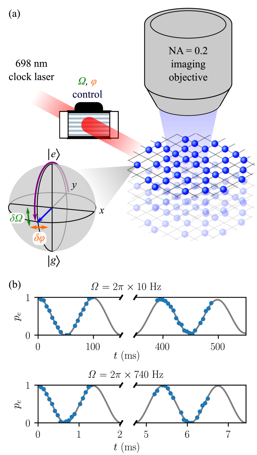
State-prepared atoms confined in an optical lattice represent a well-controlled quantum system that can be used to characterize laser frequency noise over a broad spectral range and demonstrate high-fidelity quantum state engineering. Figure 1(a) presents a schematic of our experimental setup, featuring a three-dimensional optical lattice clock [71]. A spin-polarized, deeply degenerate Fermi gas of atoms [72] is loaded into the ground band of a retro-reflected magic wavelength optical lattice [73], which quantizes the motional states of atoms along all three orthogonal directions. In this work, we operate at a lattice depth of , where denotes the recoil energy for photons and the Planck constant. At this depth, atoms are confined within separate lattice sites, effectively isolated as two-level systems with negligible tunneling and superexchange interactions [74]. Under this operating condition, the atomic coherence time is , limited primarily by Raman scattering of lattice photons [75].
The clock states of the atoms are manipulated by an intensity- and phase-controlled laser, which propagates horizontally to drive the “clock” transition between the ground state and the metastable excited state globally. To achieve a uniform Rabi frequency across the entire atomic ensemble of atoms within a spatial region of , we use a sufficiently large beam radius of . With this beam size, to scale up the clock Rabi frequency to about a few kHz we need to increase the optical power incident on the atoms to . To compensate for beam propagation losses, it is desirable to reach an optical power for the stabilized clock laser. We note this power level is sufficient to globally address thousands of atoms in a tweezer array with proper beam shaping for uniformity. High-intensity in-situ absorption imaging, implemented along the vertical axis through an objective lens, allows spatial readout of atomic density distributions with a resolution of [69, 70]. With the setup described in this article we demonstrate driving Rabi oscillations with frequencies ranging from a few Hertz to approximately , illustrated in Fig. 1(b) at Rabi frequencies and .
III Laser frequency noise reduction
For this 3D lattice-based quantum platform, the achievable Rabi frequencies are within the range of a few kHz. A feedback loop of bandwidth is sufficiently fast to reduce laser noise to the cavity’s noise floor within the spectral region of interest. We thus utilize the Pound-Drever-Hall (PDH) locking technique [76] to stabilize a external cavity diode laser (ECDL) to a narrow-linewidth ultra-low expansion (ULE) cavity as a reference with low high-frequency noise. For this laser to benefit from the long-term stability of a cryogenic silicon cavity, we employ a specifically designed stability transfer loop that utilizes a frequency comb to steer the laser to the silicon cavity at . The resulting laser sent to the atoms is spectrally tailored such that it inherits the cryogenic silicon cavity’s long-term stability and the ULE cavity’s low noise at high frequency, making it suitable for high-fidelity quantum state engineering.
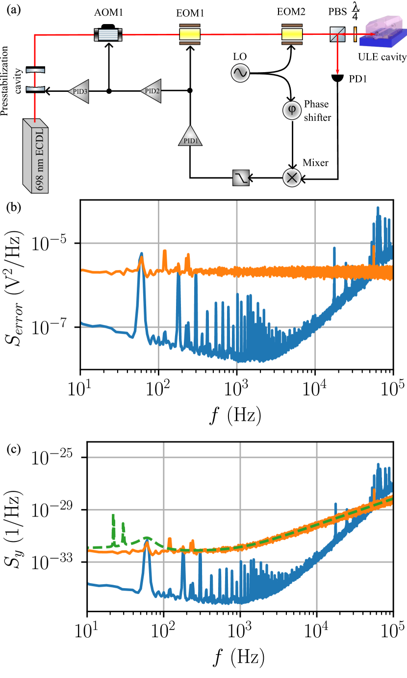
Figure 2(a) shows the block diagram of the stabilization scheme and Fig. 2(b) plots the fractional frequency noise power spectral density (PSD), , relative to the carrier. A laser is locked to a cryogenic silicon cavity (“Si3 cavity”) operating at [46]. The stability of the Si3 cavity has reached its thermal noise floor with an instability of 3.5 for 1 to over 1000 s interrogation time [68]. This cavity is the origin of the long-term stability for the clock laser and its stability is transferred to via a self-referenced femtosecond Er-fiber frequency comb (orange shaded region in Fig. 2(a)). The noise model for the Si3 cavity-stabilized comb, based on a cross-correlation evaluation against two other independent lasers (see Appendix A.1), is plotted as the orange solid line in Fig. 2(b).
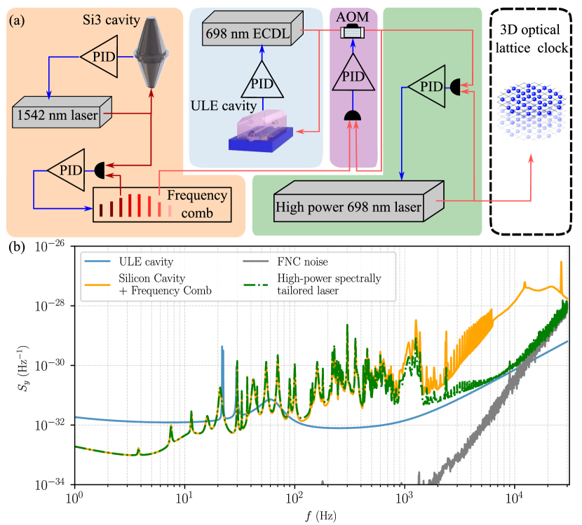
To reduce the high-frequency noise of the final spectrally tailored laser, the ECDL is PDH-locked to a ULE cavity with a thermal noise floor of [77, 78], stabilized via a high-bandwidth feedback loop (blue shaded region in Fig. 2(a)). The bandwidth PDH lock is capable of reducing the laser’s in-loop frequency noise down to the detection noise floor within , as detailed in Appendix A.2. The model of ULE cavity-stabilized laser is plotted as the blue line in Fig. 2(b).
To combine the long-term stability of the Si3 cavity and short-term stability of the ULE cavity, the ULE cavity-stabilized laser is phased-locked to the Si3 cavity-stabilized frequency comb at low frequencies by actuating on an AOM (shown in the purple shaded region in Fig. 2(a)). The fractional frequency noise PSD of the resulting spectrally tailored laser is a combination of the ULE cavity-stabilized laser noise, , and the Si3 cavity-stabilized comb, , as follows:
| (1) |
where is the complex transfer function for this phase-locked loop, encompassing the effect of the loop filter and actuator (see Appendix A.3). Qualitatively, at frequencies much lower than the unity gain frequency of , i.e. , mostly follows . On the other hand, at frequencies much higher than the unity gain frequency, i.e. , will follow .
This spectrally tailored laser features optimized spectral characteristics but its available power is only about . To increase the available power, a high-power fiber laser based on sum-frequency generation from and with a maximum output of (PRECILASER FL-SF-698-4-CW) is phase-locked to the low-power spectrally tailored laser. This high-power fiber laser has a free-running linewidth of determined from its measured frequency noise PSD, and thus a bandwidth for the phase-locked loop is sufficiently high to tightly transfer the optical phase from the ECDL to the fiber laser.
Throughout the whole laser stabilization process, light needs to be delivered to different locations via fiber links and a fiber noise cancellation technique is employed to stabilize the path length noise introduced by these fiber links [79]. The fiber noise cancellation loops involved here are based on feedback and the sum of their in-loop noise contributions is the “FNC noise” in Fig. 2(b).
The final fractional frequency noise PSD of the high-power spectrally tailored laser delivered to the atoms is presented in the green dashed line in Fig. 2. It follows the noise performance of the Si3 cavity-stabilized comb within . From to , it gradually follows the noise of the ULE cavity-stabilized laser. At frequencies above , the FNC noise becomes the dominant noise source.
IV Atom-based on-site laser frequency noise measurement
Despite all the detailed design considerations for laser noise reduction in the previous section, any uncanceled variation of the optical path length delivering light to atoms will add phase noise, reducing the rotation fidelity of the atomic state. Therefore, performing laser frequency noise measurements at the site of the atoms is highly desirable. This can be achieved by utilizing the atomic transition itself as a spectrum analyzer [80] in which the frequency noise sensitivity is manipulated via a carefully designed pulse sequence [25], while simultaneously suppressing effects related to laser intensity noise. This follows the general idea of using dynamical decoupling RF pulses to either eliminate or analyze frequency/phase noise in quantum sensors [81, 82, 83].
For any pulse sequence rotating the final state close to the equator of the Bloch sphere, the single-sided laser frequency noise power spectral density (PSD) gives rise to a variance of the final excitation probability
| (2) |
Here, is the Fourier frequency and is the Fourier transform of the time domain phase sensitivity function of the final observable [84]:
| (3) |
This function measures how much an infinitesimal phase step at time during the pulse sequence affects the final excitation fraction .
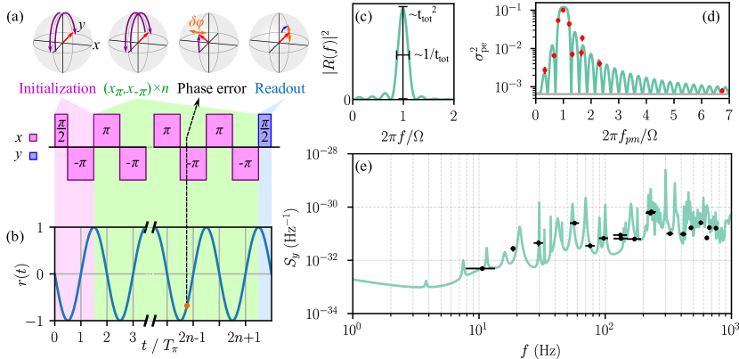
In reality, both laser frequency and intensity noise cause fluctuations of the excitation fraction and this convolution therefore bias the frequency noise measurement. To mitigate this complication, we design a pulse sequence with suppressed sensitivity to intensity noise while maintaining sensitivity to frequency noise (see Fig. 3(a)). The goal of the pulse sequence is to achieve a maximum sensitivity at a specific Fourier frequency, while allowing this target frequency to be tunable to probe noise over a frequency range of interest. Meanwhile, intensity noise is canceled by the action of neighboring pulses.
The main temporal structure of the pulse sequence resembles Ramsey spectroscopy: first, the phase sensitivity of the Bloch vector is maximized by rotating it to the equator and mapping the final azimuthal direction to the -axis by adding a rotation around the other transverse axis. In the frame co-rotating with the laser frequency, optical phase noise during the Ramsey “dark” time will lead to fluctuations of the azimuthal Bloch vector orientation. These fluctuations may be modeled as a collection of instantaneous phase jumps , which become measurable as after the final readout pulse. To reach the goal of obtaining a singly peaked sensitivity function , we require to be oscillating at a constant frequency (see Fig. 3(b,c)). This would ordinarily correspond to a continuous Rabi oscillation, and thus a smoothly modulated phase sensitivity in time, during the Ramsey “dark” time.
To reject variations of Rabi frequency () due to intensity noise, we modify the constant Rabi drive sequence to one that contains a periodic switching of the rotation direction. This improved sequence prevents an accumulation of pulse area errors over time, making this scheme robust against laser intensity noise. Here, it is important to perform the switch between rotation directions when the state vector reaches the equator of the Bloch sphere, where the phase sensitivity is in one of its extrema. Changing the rotation direction at this point does not change compared to a continuous Rabi drive without flipping the rotation axis. In the pulse sequence, this is achieved by using a series of repeated rotations, where denotes a rotation around the -axis of the Bloch sphere and denotes a rotation around the -axis. Finally, we also insert an additional pulse in the initialization section in order to suppress the sensitivity at , rejecting detrimental effects from small detunings of the laser frequency from atomic resonance. The sensitivity function of this full sequence is a windowed sine wave, resulting in a frequency-domain sensitivity with a singly peaked maximum at .
In order to experimentally verify the designed sensitivity function, we inject a controlled amount of laser noise and measure the resulting variance . The laser frequency is phase modulated at a fixed amplitude and frequency . To obtain good signal-to-noise ratio at frequencies far from the sensitivity peak, a sufficiently large value of is selected. The experimental cycle is chosen to be asynchronous with this modulation and the relative jitter between the phase modulation and the pulse sequence effectively randomizes the phase modulation. The measurement sequence applied here contains blocks of pulses and omits the pulse in the initialization.
The laser frequency PSD resulting from this added modulation is
| (4) |
where denotes the Dirac delta function. The tunability of the phase modulation allows probing the atomic sensitivity function without having to change other parameters, e.g. . Therefore, assuming the intrinsic laser noise is stationary throughout the experiment, the sensitivity function can be characterized without knowing the structure of the laser noise. The laser contribution can be separately quantified from a measurement at a fixed value of without modulation applied (horizontal gray line in Fig. 3(d)). Adding these two independent noise sources, , we can compare the fluctuations expected from the predicted sensitivity to the experimental results (green line and red points in Fig. 3(d)). Here, we use Eqs. (2) and (4) to convert PSD into , and we also take into account the saturation effect in above due to the curvature of the Bloch sphere (see Appendix B).
After certifying the sensitivity function shown in Figs. 3(b-c) we now apply this tunable atomic spectrum analyzer to probe and verify the laser noise spectrum. For this, we repeatedly apply the pulse sequence shown in Fig. 3(a) with different Rabi frequencies and numbers of segments to tune the center frequency and bandwidth of the sensitivity function to probe the laser noise. Here, the center frequency is roughly given by and the bandwidth by the inverse of the total pulse duration , where is the pulse duration. The peak of the sensitivity function scales as , which results in a scaling for the variance of the final excited fraction. By integrating the laser PSD within the sensitivity bandwidth and using it to represent an average value over the probe window, we can move it out of the integral in Eq. (2) and therefore extract a value for from the measured variance . Figure 3(e) compares these values (black points with horizontal bars indicating the bandwidth) with the laser noise model (reproduced from the green dashed line in Fig. 2(b)), finding excellent agreement.
V Randomized benchmarking
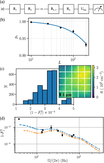
With this spectrally tailored laser, how well can we control the optical qubit? To quantify the fidelity of quantum state engineering, we perform randomized benchmarking based on single-qubit Clifford gates to measure the average gate fidelity [85, 86, 87]. Fig. 4(a) shows a schematic of the pulse sequence for the randomized benchmarking. We initialize atoms in the excited state and apply a sequence of randomly selected elements of the single-qubit Clifford group with uniform probability. These are realized by a combination of and rotations around the and axes as tabulated in Table 1, with an average pulse area of per Clifford gate. A recovery pulse is applied after the random Clifford gate sequence. For a given Clifford gate sequence, is randomly chosen from a set of four Clifford gates that will restore the Bloch vector to under ideal operation. By applying the clock laser to all atoms simultaneously and measuring the populations in and , we obtain a value for in each realization of the experiment.
The gate fidelity averaged over all single-qubit Clifford gates can be extracted by measuring how the probability of reaching the correct output state, i.e. , decays when increases. This is probability is captured by the fidelity between the pure initial state specified by the density matrix and the final state ,
| (5) |
Applying a purely depolarizing model that assumes the only effect of gate errors to be an increase of the mixing of , the fidelity of the full benchmarking sequence is given by [87]
| (6) |
where is the depolarization probability for a single pulse and is the state preparation and measurement error. The average fidelity of a single Clifford gate is .
Figure 4(b) shows randomized benchmarking results for gates at Rabi frequency for 3000 atoms. We measure a single-qubit gate fidelity averaged over the entire cloud and all 24 single-qubit Clifford gates. The distribution of fidelities across the atomic cloud is narrowly peaked around this value, as shown in the histogram in Fig. 4(c), which is obtained by sub-dividing the images into a grid (cf. inset). This indicates an excellent uniformity of high-fidelity state manipulation across the entire sample of lattice-confined atoms.
To study how laser frequency noise impacts the fidelity of pulses, randomized benchmarking measurements at different Rabi frequencies are performed. The experiment results are plotted with black dots in Fig. 4(d) and compared to a numerical simulation (blue dashed line) based primarily on the laser frequency noise PSD, showing good agreement between the two. Contributions from atomic decay and decoherence are small and only relevant at time scales beyond [75]. Small deviations in certain Rabi frequency ranges arise from peaks in the PSD from the vibration of the cavity that may drift over time within limited ranges. Towards higher Rabi frequencies we observe an increasing fidelity, consistent with the understanding that shorter pulses should lead to less sensitivity to fluctuations.
VI Outlook
Development of highly stable lasers provides critically important capabilities for the continued advance of quantum science and technology. The realization of a spectrally tailored high-power laser for driving optical transitions highlights an example where systematic considerations of laser spectral noise are integrated closely with an atom-based quantum system for performance characterization and verification. We hope this case study serves a useful technical purpose for other researchers interested in developing highly stabilized lasers for their specific applications. Particularly, the reported system has already demonstrated a highly desired property of achieving a record fidelity for manipulating a large and scalable number of optical qubits.
To further improve the fidelity and robustness of optical manipulations based on a sequence of laser pulses, we can consider two approaches. The first is to engineer pulses that are less sensitive to uncontrolled experiment parameters, e.g. employment of composite pulses [88], pulse shaping in amplitude and phase [89, 90] or utilization of optimal control algorithm to design pulses [91]. The other is to further reduce the relevant high-frequency noise by developing even faster frequency transducers to advance servo bandwidth to increasingly higher values. Feedforward techniques [65, 92] can also be employed to complement servo loops to mitigate frequency noise beyond the bandwidth of available feedback techniques.
The vastly improved fidelity for driving optical transitions in scalable and highly coherent atomic/molecular systems will improve atom-based quantum computing. Reduction of quantum state preparation error is also in strong demand for realizing metrologically useful spin squeezing. With the capability of applying hundreds of pulses to drive an optical transition without significantly losing contrast, we can Floquet engineer an effective Hamiltonian of a many-body system to decouple unwanted interactions or to study novel emergent phenomena using specially designed pulses [45]. This method has already found a widespread use in the microwave/RF domain due to the relative ease for high-fidelity RF pulses [93, 94, 95]. However, because of the limited laser stability, this approach has not achieved similar popularity in the optical domain. We hope to change this landscape with the development reported here. Particularly for our 3D optical lattice clock platform, existing interactions such as collective dipolar couplings [26] and superexchange interactions [74] can be engineered to realize longer atomic coherence and metrologically useful entangled states [96].
Acknowledgment We are grateful to A. Aeppli, Z. Hu, J. Hur, D. Kedar, Y. Lee, M. Miklos, J. M. Robinson, Y. M. Tso, W. Warfield, Z. Yao, and J. L. Hall for technical discussions and assistance. We thank N. D. Oppong, E. Bohr, J. P. Covey, B. Bloom, and J. Home for careful reading of the manuscript and for providing insightful comments. Funding for this work is provided primarily by DOE Center of Quantum System Accelerator, and also by V. Bush Fellowship, NSF QLCI OMA-2016244, NSF JILA-PFC PHY-2317149, and NIST. S. L. acknowledges funding from the Alexander von Humboldt Foundation and B. L. from the Lindemann Trust.
Author contributions All authors contributed to the stable laser development. The atom-based measurement was carried out by L.Y., S.L., W.R.M., M.N.F., and J.Y. on the JILA Sr2 quantum gas-3D lattice clock platform. All authors contributed to data analysis and writing of the paper.
Data availability
All data is available from the corresponding authors on reasonable request.
Competing interests
The authors declare no competing interests.
Appendix A Details of laser noise modeling
In this section we provide further technical details about the characterization and modeling of laser noise components when designing the spectrally tailored high-power laser described in Sec. III.
A.1 Si3 cavity noise characterization
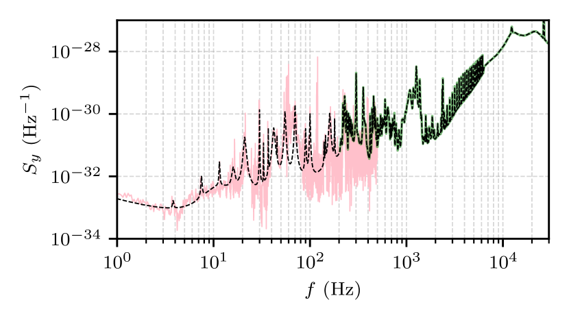
The noise of the laser frequency stabilized to the Si3 cavity is evaluated with a cross-correlation measurement [97] against two other independent frequency-stabilized lasers: a cryogenic silicon cavity operating at and a room temperature ULE cavity. The cross-correlation measurement is based on the recorded heterodyne beat frequencies among these three cavities, and a frequency comb is needed to bridge the spectral gap between of ULE and of silicon. Specifically, the cross-correlation of the optical beats between Si3 and the other two cavities provides the frequency noise power spectral density of the Si3 cavity-stabilized laser. We perform the cross-correlation measurement using two different approaches. First, we use a frequency counter to simultaneously record the frequency of the two optical beats. The counter has a minimum gate time of , which limits the sampling frequency to about . Therefore, we discard information above from the counter-based measurement. This counter-based cross-spectral density evaluation is represented by the pink trace in Fig. 5. In order to retrieve high-frequency noise of the Si3 cavity-stabilized laser, we use two phase-locked tracking filters to record the phase information of the two relevant optical beats. The tracking filters have bandwidth and they are limited by their intrinsic noise below . Therefore, the tracking filter-based cross-correlation measurement provides information of the Si3 cavity-stabilized laser from to (shown as the green trace in Fig. 5). Measurements based on these two different methods are consistent with each other in their frequency overlapped region. The additive noise of the frequency comb is inferred from our previous work [68] and grants a negligible contribution relative to the Si3 noise.
Based on the counter-based result of cross-spectral density measurement, we use the following function to model the noise of Si3 cavity-stabilized comb for noise below :
| (7) |
Here we include a thermal frequency flicker noise term ( = 1.5 10-33), a white frequency noise term ( = 4.0 10-34 Hz-1), a white phase noise term ( = 4.3 10-37 Hz-3), and a series of resonant features. Ref. [68] provides similar information for . The and peaks visible in the counter measurement are artificial, as confirmed by the direct atomic spectral analysis, and are therefore not represented in the noise model.
As for the noise at , we directly interpolate the tracking filter-based cross spectral density measurement result to describe the noise of Si3 cavity-stabilized comb. The model is plotted as the black dashed line in Fig. 5 to compare against the cross-correlation measurement results.
A.2 High-bandwidth PDH lock to a ULE cavity
Instead of directly locking the external cavity diode laser (ECDL) to the ULE cavity, our setup features an additional prestabilization stage with an electro-optic modulator (EOM) as a fast actuator (see Fig. 6(a) for a schematic). The ECDL is prestabilized to a medium finesse cavity (finesse of 50,000, linewidth of ) with an auxiliary PDH loop (not shown in the schematic). The transmission light of this prestabilization cavity is the starting point for the rest of the high-bandwidth PDH lock to the narrow linewidth () ULE cavity. A resonant EOM (EOM2) is driven with a RF signal to generate sidebands on the incident light to the ULE cavity for the PDH lock. A photodiode (PD1) collects the reflected light from the cavity, and its photocurrent is demodulated to generate the PDH error signal. This error signal is passed to a series of proportional-integral-derivative (PID) loop filters and actuators, whose design is inspired by Ref. [51, 52]. PID1 directly takes the PDH error signal as its input, and a low delay time amplification stage drives a broadband EOM (EOM1), which can realize bandwidth but with a limited dynamic range for correcting phase errors. To increase the servo range, the output of PID1 serves as the input to PID2, which controls the RF drive frequency to an acousto-optic modulator (AOM1) with a bandwidth of . Finally, the output of PID2 serves as the input error signal for PID3, which controls the length of the prestabilization cavity with a piezoelectric actuator. This final loop has a few kHz bandwidth but with the largest servo correction dynamics range. The three PID loops are connected in series to prevent partial cancellation of their outputs and still reach an overall bandwidth of .
The frequency noise of a cavity-stabilized laser is determined by the noise of the cavity itself, the in-loop error of the servo loop, and the residual photodetection noise. For our system, the in-loop error is below the detection noise floor up to . This means that the actual in-loop noise within is dominated by the white shot noise of PDH photo detection. A cavity serves as a frequency noise discriminator for laser frequency/phase fluctuation at time scales slower than the cavity lifetime and it turns into a phase noise discriminator for fluctuation faster than the cavity lifetime [76]. Thus, the slope of the PDH frequency discriminator has a following frequency-dependent form [98, 99]:
| (8) |
where is the slope of the DC PDH error signal, is the Fourier frequency of laser noise, and is the HWHM of the cavity. For the ULE cavity utilized in our setup, = 1 kHz [77]. In the frequency domain where the in-loop error signal is below the detection noise floor, the photon shot noise of the PDH detector is turned to white frequency noise for and then white phase noise for .
The frequency noise of the ULE cavity up to of was previously characterized using atoms, revealing its thermal noise floor and vibration-induced resonance peaks [80]. With the additional characterization between and , we can sum all the contributions and reach the following model for the frequency noise of the ULE cavity-stabilized laser:
| (9) |
Here a thermal flicker noise term (Hz2), a white frequency noise term (Hz2/Hz), a white phase noise term () and a series of resonant features are included. The thermal flicker noise term and resonant features are adopted from Ref. [80] while the white frequency noise term and the white phase noise term are updated.
Figure 6(b) displays the PDH in-loop error signal when the laser is locked to the ULE cavity (blue) versus the PDH photo detection noise floor (orange). The photon shot noise is measured when the laser frequency is tuned far away from the cavity resonance and the same amount of optical power is incident on the PDH photodetector as compared to when the laser is locked to the cavity. The in-loop servo error noise is below the photo-detection noise floor for . The corresponding laser frequency noise contributions are plotted in Fig. 6(c) against the model of the ULE cavity-stabilized laser.
A.3 Si cavity to ULE cavity stability transfer loop
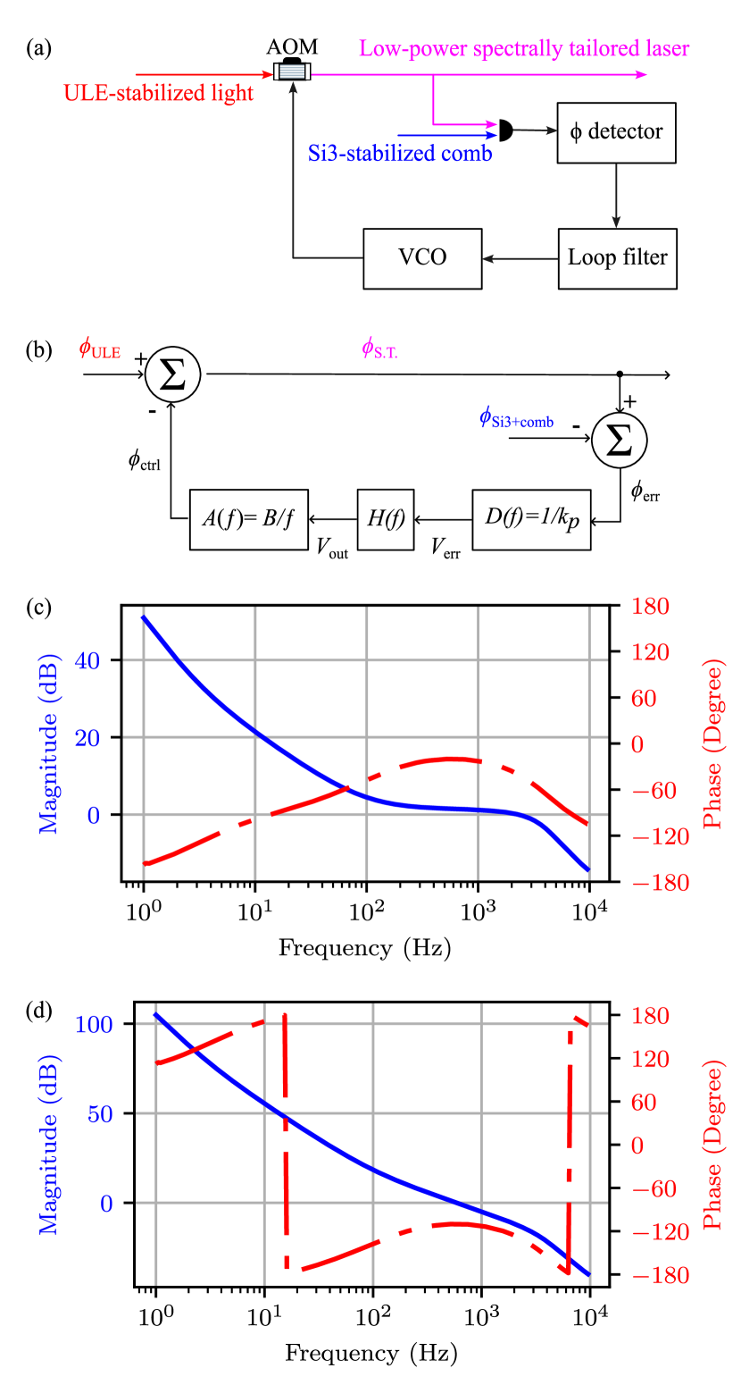
The schematic of the stability transfer loop, which was initially set up for the Sr clock operation, can be found in Ref. [100]. For this work we use a simplified version shown in Fig. 7(a) to illustrate the concepts. The ULE cavity-stabilized laser passes through an AOM and the first-order diffracted light is used to beat against the Si3 cavity-stabilized comb light. The phase noise of the beat signal is detected against a stable RF reference via a phase detector, and the derived error signal goes through a loop filter to drive a voltage-controlled oscillator (VCO), which provides the RF drive of the AOM. Figure 7(b) illustrates the basic model of this phase-locked loop in frequency domain. Here, and represent the optical phase of the ULE and Si3 cavity-stabilized lasers, respectively. These are used to derive the spectrally tailored laser phase as
| (10) |
where is the phase correction signal of the AOM derived by the loop. The phase detector converts the phase error to a voltage , which is the input signal of the feedback loop. For the frequency range relevant to our system the transfer function
| (11) |
of the phase detector is essentially a constant, where is the conversion factor. Fig. 7(c) shows a measured Bode plot of the loop filter transfer function . Its output serves as the control signal for the VCO driving the AOM, which has a frequency-tuning sensitivity to the control voltage of . The transfer function of this frequency actuator contains an intrinsic 1/ for phase actuation,
| (12) |
where and is the imaginary unit. Thus,
| (13) |
and
| (14) |
By combining Eqs. (10), (13) and (14) we obtain
| (15) |
Substituting Eqs. (14) and (15) into Eq. (10), we arrive at
| (16) |
with the open-loop gain of the stability transfer loop
| (17) |
The Bode plot of is shown in Fig. 7(d). Because the ULE and Si3 noise sources are independent, one obtains the noise power of Eq. (1) by simply squaring the summands in Eq. (16).
Appendix B Accounting for saturation effects in the fluctuation of the excitation probability
Eq. (2) is derived in the limit that the fluctuations of the final excitation probability due to laser noise are small. This is the limit where the curvature of the Bloch sphere is negligible. In case of large excursions of the excitation probability away from the equator, will not grow linearly with the laser noise, but instead become saturated. The saturation arises from the fact that the maximum deviation of can only be , i.e. when reaching either pole of the Bloch sphere. Thus, to deal with the saturation effect, instead of analyzing , we should use the polar angle of the final state on the Bloch sphere as a quantity in the laser noise model.
For the treatment of laser noise, we have initially performed a linearization of the laser phase fluctuations (cf. Eq. (3)), which also constrains all derived quantities to the linear limit. Eq. (2) is hence applicable to the variance of and this equivalence holds even beyond the point where starts showing saturation effects. Therefore, instead of , we now utilize to derive a prediction of the variance of the excitation probability , which is valid even when saturates.
For this, we introduce a parametrization of the excitation probability in terms of the polar deviation from the equator,
| (18) |
In line with our noise models, we assume to be a Gaussian random variable, i.e. its probability distribution is given by
| (19) |
with variance given by Eq. (2). By applying Eqs. (18) and (19) we obtain expressions for the first and second moment of in dependence of or rather :
| (20) | ||||
This allows expressing the variance of the excitation probability as
| (21) |
where is given by Eq. (2). Note that this expression is valid so long as the error of the final excitation probability stays linear with the phase error , which remains true for fluctuation much larger than those leading to a saturation of due to the curvature of the Bloch sphere.
Appendix C Numerical simulation of gate fidelity
Our experimental realization of each element of single-qubit Clifford group is tabulated in Table 1. To numerically study the averaged single-qubit Clifford gate fidelity, we use the following master equation to simulate the randomized benchmarking experiment:
| (22) |
Here, is the atomic density matrix,
| (23) |
is the Lindblad dissipator that captures the atom-atom decoherence effect, and
| (24) |
is the Hamiltonian (with rotating-wave approximation applied) that captures the dynamics of the driven two-level system in the presence of laser noise. Here, is the excited state decay rate, the additional decoherence rate, the laser detuning, the Rabi frequency, the laser phase defining the rotational axis and captures the laser noise.
In the limit of and , Eq. (22) will be reduced to the following form:
| (25) | ||||
where one can easily find that is the excited state population decay rate and is the total decoherence rate. For this work, the operational lattice depth is . This is a regime where is limited by Raman scattering of lattice photons [75]. Based on the operational lattice depth, we use for the numerical modeling. We experimentally measure the atomic coherence time of via extracting the decay time constant of Ramsey contrast using imaging spectroscopy [69], i.e. . Therefore, the parameter in Eq. (23) is .
is a deterministic phase that defines the rotation axis. corresponds to the rotation along , , , axis. And in Eq.(24) is the stochastic phase fluctuation due to laser phase noise. For each run of the simulation, a time trace of is generated based on the single-sided phase noise power spectral density of the laser [65, 44]:
| (26) |
where is the random phase offset of Fourier frequency and is the frequency resolution of . is related to the fractional frequency noise of laser discussed in Sec. III by , where is the carrier frequency of the clock laser.
We simulate the randomized benchmarking experiment by selecting 30 randomly chosen gate strings for each and utilize Eq. (6) to fit the final of the numerical simulation results to extract the prediction of shown in Fig. 4. For each gate string we integrate the evolution of the density matrix for 50 different phase traces and average the final to obtain an estimate for the fidelity of the corresponding gate sequence. Because generating the phase traces for durations of multiple seconds becomes computationally expensive, we re-use the same phase traces for each Clifford gate string. The randomization in selecting the gate strings should provide a sufficient phase-randomization such that the averages extracted by the simulations provide a faithful comparison to our experimental data.
| index | |||||
|---|---|---|---|---|---|
| 1 | - | - | - | 0 | |
| 2 | |||||
| 3 | - | ||||
| 4 | |||||
| 5 | - | - | |||
| 6 | |||||
| 7 | - | - | |||
| 8 | |||||
| 9 | - | ||||
| 10 | - | - | |||
| 11 | - | ||||
| 12 | |||||
| 13 | - | ||||
| 14 | - | ||||
| 15 | - | - | |||
| 16 | - | ||||
| 17 | - | ||||
| 18 | - | ||||
| 19 | - | ||||
| 20 | - | - | |||
| 21 | - | ||||
| 22 | - | - | |||
| 23 | - | ||||
| 24 | - |
References
- Ye and Zoller [2024] J. Ye and P. Zoller, Essay: Quantum sensing with atomic, molecular, and optical platforms for fundamental physics, Phys. Rev. Lett. 132, 190001 (2024).
- Gaebler et al. [2016] J. P. Gaebler, T. R. Tan, Y. Lin, Y. Wan, R. Bowler, A. C. Keith, S. Glancy, K. Coakley, E. Knill, D. Leibfried, and D. J. Wineland, High-fidelity universal gate set for ion qubits, Phys. Rev. Lett. 117, 060505 (2016).
- Clark et al. [2021] C. R. Clark, H. N. Tinkey, B. C. Sawyer, A. M. Meier, K. A. Burkhardt, C. M. Seck, C. M. Shappert, N. D. Guise, C. E. Volin, S. D. Fallek, H. T. Hayden, W. G. Rellergert, and K. R. Brown, High-fidelity bell-state preparation with optical qubits, Phys. Rev. Lett. 127, 130505 (2021).
- Leu et al. [2023] A. D. Leu, M. F. Gely, M. A. Weber, M. C. Smith, D. P. Nadlinger, and D. M. Lucas, Fast, high-fidelity addressed single-qubit gates using efficient composite pulse sequences, Phys. Rev. Lett. 131, 120601 (2023).
- [5] Alpine quantum technologies, see for example , https://www.aqt.eu .
- Da Silva et al. [2024] M. Da Silva, C. Ryan-Anderson, J. Bello-Rivas, A. Chernoguzov, J. Dreiling, C. Foltz, F. Frachon, J. Gaebler, T. Gatterman, L. Grans-Samuelsson, et al., Demonstration of logical qubits and repeated error correction with better-than-physical error rates, arXiv preprint arXiv:2404.02280 (2024).
- Löschnauer et al. [2024] C. Löschnauer, J. M. Toba, A. Hughes, S. King, M. Weber, R. Srinivas, R. Matt, R. Nourshargh, D. Allcock, C. Ballance, et al., Scalable, high-fidelity all-electronic control of trapped-ion qubits, arXiv preprint arXiv:2407.07694 (2024).
- Evered et al. [2023] S. J. Evered, D. Bluvstein, M. Kalinowski, S. Ebadi, T. Manovitz, H. Zhou, S. H. Li, A. A. Geim, T. T. Wang, N. Maskara, et al., High-fidelity parallel entangling gates on a neutral-atom quantum computer, Nature 622, 268 (2023).
- Ma et al. [2023] S. Ma, G. Liu, P. Peng, B. Zhang, S. Jandura, J. Claes, A. P. Burgers, G. Pupillo, S. Puri, and J. D. Thompson, High-fidelity gates and mid-circuit erasure conversion in an atomic qubit, Nature 622, 279 (2023).
- Bluvstein et al. [2024] D. Bluvstein, S. J. Evered, A. A. Geim, S. H. Li, H. Zhou, T. Manovitz, S. Ebadi, M. Cain, M. Kalinowski, D. Hangleiter, et al., Logical quantum processor based on reconfigurable atom arrays, Nature 626, 58 (2024).
- Radnaev et al. [2024] A. Radnaev, W. Chung, D. Cole, D. Mason, T. Ballance, M. Bedalov, D. Belknap, M. Berman, M. Blakely, I. Bloomfield, et al., A universal neutral-atom quantum computer with individual optical addressing and non-destructive readout, arXiv preprint arXiv:2408.08288 (2024).
- Tsai et al. [2024] R. B.-S. Tsai, X. Sun, A. L. Shaw, R. Finkelstein, and M. Endres, Benchmarking and linear response modeling of high-fidelity Rydberg gates, arXiv preprint arXiv:2407.20184 (2024).
- Muniz et al. [2024] J. Muniz, M. Stone, D. Stack, M. Jaffe, J. Kindem, L. Wadleigh, E. Zalys-Geller, X. Zhang, C.-A. Chen, M. Norcia, et al., High-fidelity universal gates in the 171Yb ground state nuclear spin qubit, arXiv preprint arXiv:2411.11708 (2024).
- Eckner et al. [2023] W. J. Eckner, N. Darkwah Oppong, A. Cao, A. W. Young, W. R. Milner, J. M. Robinson, J. Ye, and A. M. Kaufman, Realizing spin squeezing with Rydberg interactions in an optical clock, Nature 621, 734 (2023).
- Finkelstein et al. [2024] R. Finkelstein, R. B.-S. Tsai, X. Sun, P. Scholl, S. Direkci, T. Gefen, J. Choi, A. L. Shaw, and M. Endres, Universal quantum operations and ancilla-based read-out for tweezer clocks, Nature 634, 321 (2024).
- Cao et al. [2024] A. Cao, W. J. Eckner, T. Lukin Yelin, A. W. Young, S. Jandura, L. Yan, K. Kim, G. Pupillo, J. Ye, N. Darkwah Oppong, et al., Multi-qubit gates and Schrödinger cat states in an optical clock, Nature 634, 315 (2024).
- Lis et al. [2023] J. W. Lis, A. Senoo, W. F. McGrew, F. Rönchen, A. Jenkins, and A. M. Kaufman, Midcircuit operations using the omg architecture in neutral atom arrays, Phys. Rev. X 13, 041035 (2023).
- Madjarov et al. [2020] I. S. Madjarov, J. P. Covey, A. L. Shaw, J. Choi, A. Kale, A. Cooper, H. Pichler, V. Schkolnik, J. R. Williams, and M. Endres, High-fidelity entanglement and detection of alkaline-earth Rydberg atoms, Nat. Phys. 16, 857 (2020).
- Levine et al. [2018] H. Levine, A. Keesling, A. Omran, H. Bernien, S. Schwartz, A. S. Zibrov, M. Endres, M. Greiner, V. Vuletić, and M. D. Lukin, High-fidelity control and entanglement of Rydberg-atom qubits, Phys. Rev. Lett. 121, 123603 (2018).
- Oskin et al. [2002] M. Oskin, F. T. Chong, and I. L. Chuang, A practical architecture for reliable quantum computers, Computer 35, 79 (2002).
- Knill [2010] E. Knill, Quantum computing, Nature 463, 441 (2010).
- Preskill [1998] J. Preskill, Reliable quantum computers, Proc. R. Soc. Lond. A. 454, 385 (1998).
- Nielsen and Chuang [2010] M. A. Nielsen and I. L. Chuang, Quantum computation and quantum information (Cambridge university press, 2010).
- Kennedy et al. [2020] C. J. Kennedy, E. Oelker, J. M. Robinson, T. Bothwell, D. Kedar, W. R. Milner, G. E. Marti, A. Derevianko, and J. Ye, Precision metrology meets cosmology: improved constraints on ultralight dark matter from atom-cavity frequency comparisons, Phys. Rev. Lett. 125, 201302 (2020).
- Kolkowitz et al. [2016] S. Kolkowitz, I. Pikovski, N. Langellier, M. D. Lukin, R. L. Walsworth, and J. Ye, Gravitational wave detection with optical lattice atomic clocks, Phys. Rev. D 94, 124043 (2016).
- Hutson et al. [2024] R. B. Hutson, W. R. Milner, L. Yan, J. Ye, and C. Sanner, Observation of millihertz-level cooperative lamb shifts in an optical atomic clock, Science 383, 384 (2024).
- Pedrozo-Penafiel et al. [2020] E. Pedrozo-Penafiel, S. Colombo, C. Shu, A. F. Adiyatullin, Z. Li, E. Mendez, B. Braverman, A. Kawasaki, D. Akamatsu, Y. Xiao, and V. Vuletic, Entanglement on an optical atomic-clock transition, Nature 588, 414 (2020).
- Robinson et al. [2024] J. M. Robinson, M. Miklos, Y. M. Tso, C. J. Kennedy, T. Bothwell, D. Kedar, J. K. Thompson, and J. Ye, Direct comparison of two spin-squeezed optical clock ensembles at the 10-17 level, Nat. Phys. 20, 208 (2024).
- Ni et al. [2008] K.-K. Ni, S. Ospelkaus, M. H. G. de Miranda, A. Pe’er, B. Neyenhuis, J. J. Zirbel, S. Kotochigova, P. S. Julienne, D. S. Jin, and J. Ye, A high phase-space-density gas of polar molecules, Science 322, 231 (2008).
- Maddox et al. [2024] B. P. Maddox, J. M. Mortlock, T. R. Hepworth, A. P. Raghuram, P. D. Gregory, A. Guttridge, and S. L. Cornish, Enhanced quantum state transfer via feedforward cancellation of optical phase noise, arXiv preprint arXiv:2407.09119 (2024).
- Geva et al. [1995] E. Geva, R. Kosloff, and J. Skinner, On the relaxation of a two-level system driven by a strong electromagnetic field, J. Chem. Phys. 102, 8541 (1995).
- Makhlin and Shnirman [2003] Y. Makhlin and A. Shnirman, Dephasing of qubits by transverse low-frequency noise, JEPT Lett. 78, 497 (2003).
- Ithier et al. [2005] G. Ithier, E. Collin, P. Joyez, P. J. Meeson, D. Vion, D. Esteve, F. Chiarello, A. Shnirman, Y. Makhlin, J. Schriefl, and G. Schön, Decoherence in a superconducting quantum bit circuit, Phys. Rev. B 72, 134519 (2005).
- Chen et al. [2012] Z. Chen, J. G. Bohnet, J. M. Weiner, and J. K. Thompson, General formalism for evaluating the impact of phase noise on bloch vector rotations, Phys. Rev. A 86, 032313 (2012).
- Yan et al. [2013] F. Yan, S. Gustavsson, J. Bylander, X. Jin, F. Yoshihara, D. G. Cory, Y. Nakamura, T. P. Orlando, and W. D. Oliver, Rotating-frame relaxation as a noise spectrum analyser of a superconducting qubit undergoing driven evolution, Nat. Commun. 4, 2337 (2013).
- Paladino et al. [2014] E. Paladino, Y. M. Galperin, G. Falci, and B. L. Altshuler, 1/ noise: Implications for solid-state quantum information, Rev. Mod. Phys. 86, 361 (2014).
- Yoshihara et al. [2014] F. Yoshihara, Y. Nakamura, F. Yan, S. Gustavsson, J. Bylander, W. D. Oliver, and J.-S. Tsai, Flux qubit noise spectroscopy using rabi oscillations under strong driving conditions, Phys. Rev. B 89, 020503 (2014).
- Jing et al. [2014] J. Jing, P. Huang, and X. Hu, Decoherence of an electrically driven spin qubit, Phys. Rev. A 90, 022118 (2014).
- Ball et al. [2016] H. Ball, W. D. Oliver, and M. J. Biercuk, The role of master clock stability in quantum information processing, npj Quantum Inf 2, 1 (2016).
- Green et al. [2012] T. Green, H. Uys, and M. J. Biercuk, High-order noise filtering in nontrivial quantum logic gates, Phys. Rev. Lett. 109, 020501 (2012).
- Green et al. [2013] T. J. Green, J. Sastrawan, H. Uys, and M. J. Biercuk, Arbitrary quantum control of qubits in the presence of universal noise, New J. Phys. 15, 095004 (2013).
- de Léséleuc et al. [2018] S. de Léséleuc, D. Barredo, V. Lienhard, A. Browaeys, and T. Lahaye, Analysis of imperfections in the coherent optical excitation of single atoms to Rydberg states, Phys. Rev. A 97, 053803 (2018).
- Day et al. [2022] M. L. Day, P. J. Low, B. White, R. Islam, and C. Senko, Limits on atomic qubit control from laser noise, npj Quantum Inf 8, 72 (2022).
- Jiang et al. [2023] X. Jiang, J. Scott, M. Friesen, and M. Saffman, Sensitivity of quantum gate fidelity to laser phase and intensity noise, Phys. Rev. A 107, 042611 (2023).
- Choi et al. [2020] J. Choi, H. Zhou, H. S. Knowles, R. Landig, S. Choi, and M. D. Lukin, Robust dynamic Hamiltonian engineering of many-body spin systems, Phys. Rev. X 10, 031002 (2020).
- Matei et al. [2017] D. G. Matei, T. Legero, S. Häfner, C. Grebing, R. Weyrich, W. Zhang, L. Sonderhouse, J. M. Robinson, J. Ye, F. Riehle, and U. Sterr, lasers with sub-10 mHz linewidth, Phys. Rev. Lett. 118, 263202 (2017).
- Robinson et al. [2019] J. M. Robinson, E. Oelker, W. R. Milner, W. Zhang, T. Legero, D. G. Matei, F. Riehle, U. Sterr, and J. Ye, Crystalline optical cavity at 4 K with thermal-noise-limited instability and ultralow drift, Optica 6, 240 (2019).
- Cundiff and Ye [2003] S. T. Cundiff and J. Ye, Colloquium: Femtosecond optical frequency combs, Rev. Mod. Phys. 75, 325 (2003).
- Ludlow et al. [2015] A. D. Ludlow, M. M. Boyd, J. Ye, E. Peik, and P. O. Schmidt, Optical atomic clocks, Rev. Mod. Phys. 87, 637 (2015).
- Newbury and Swann [2007] N. R. Newbury and W. C. Swann, Low-noise fiber-laser frequency combs (invited), J. Opt. Soc. Am. B 24, 1756 (2007).
- Hall and Hänsch [1984] J. L. Hall and T. W. Hänsch, External dye-laser frequency stabilizer, Opt. Lett. 9, 502 (1984).
- Zhu and Hall [1993] M. Zhu and J. L. Hall, Stabilization of optical phase/frequency of a laser system: application to a commercial dye laser with an external stabilizer, J. Opt. Soc. Am. B 10, 802 (1993).
- Schoof et al. [2001] A. Schoof, J. Grünert, S. Ritter, and A. Hemmerich, Reducing the linewidth of a diode laser below 30 Hz by stabilization to a reference cavity with a finesse above , Opt. Lett. 26, 1562 (2001).
- Le Gouët et al. [2009] J. Le Gouët, J. Kim, C. Bourassin-Bouchet, M. Lours, A. Landragin, and F. Pereira Dos Santos, Wide bandwidth phase-locked diode laser with an intra-cavity electro-optic modulator, Opt. Commun. 282, 977 (2009).
- Appel et al. [2009] J. Appel, A. MacRae, and A. I. Lvovsky, A versatile digital ghz phase lock for external cavity diode lasers, Meas. Sci. Technol. 20, 055302 (2009).
- Gatti et al. [2015] D. Gatti, R. Gotti, T. Sala, N. Coluccelli, M. Belmonte, M. Prevedelli, P. Laporta, and M. Marangoni, Wide-bandwidth pound-drever-hall locking through a single-sideband modulator, Opt. Lett. 40, 5176 (2015).
- Endo and Schibli [2018] M. Endo and T. R. Schibli, Residual phase noise suppression for pound-drever-hall cavity stabilization with an electro-optic modulator, OSA Continuum 1, 116 (2018).
- Preuschoff et al. [2022] T. Preuschoff, P. Baus, M. Schlosser, and G. Birkl, Wideband current modulation of diode lasers for frequency stabilization, Rev. Sci. Instrum. 93 (2022).
- Hald and Ruseva [2005] J. Hald and V. Ruseva, Efficient suppression of diode-laser phase noise by optical filtering, J. Opt. Soc. Am. B 22, 2338 (2005).
- Nazarova et al. [2008] T. Nazarova, C. Lisdat, F. Riehle, and U. Sterr, Low-frequency-noise diode laser for atom interferometry, J. Opt. Soc. Am. B 25, 1632 (2008).
- Bagheri et al. [2009] M. Bagheri, F. Aflatouni, A. Imani, A. Goel, and H. Hashemi, Semiconductor laser phase-noise cancellation using an electrical feed-forward scheme, Opt. Lett. 34, 2979 (2009).
- Aflatouni et al. [2010] F. Aflatouni, M. Bagheri, and H. Hashemi, Design methodology and architectures to reduce the semiconductor laser phase noise using electrical feedforward schemes, IEEE Trans. Microw. Theory Techn. 58, 3290 (2010).
- Aflatouni and Hashemi [2012] F. Aflatouni and H. Hashemi, Wideband tunable laser phase noise reduction using single sideband modulation in an electro-optical feed-forward scheme, Opt. Lett. 37, 196 (2012).
- Lintz et al. [2017] M. Lintz, D.-H. Phung, J.-P. Coulon, B. Faure, and T. Léveque, Note: Efficient diode laser line narrowing using dual, feed-forward+ feed-back laser frequency control, Rev. Sci. Instrum. 88 (2017).
- Li et al. [2022] L. Li, W. Huie, N. Chen, B. DeMarco, and J. P. Covey, Active cancellation of servo-induced noise on stabilized lasers via feedforward, Phys. Rev. Appl. 18, 064005 (2022).
- Chao et al. [2024a] Y.-X. Chao, Z.-X. Hua, X.-H. Liang, Z.-P. Yue, L. You, and M. K. Tey, Pound-drever-hall feedforward: laser phase noise suppression beyond feedback, Optica 11, 945 (2024a).
- Denecker et al. [2024] T. Denecker, Y. T. Chew, O. Guillemant, G. Watanabe, T. Tomita, K. Ohmori, and S. de Léséleuc, Measurement and feed-forward correction of the fast phase noise of lasers, arXiv preprint arXiv:2411.10021 (2024).
- Oelker et al. [2019] E. Oelker, R. Hutson, C. Kennedy, L. Sonderhouse, T. Bothwell, A. Goban, D. Kedar, C. Sanner, J. Robinson, G. Marti, et al., Demonstration of 4.8 10-17 stability at 1 s for two independent optical clocks, Nature Photonics 13, 714 (2019).
- Marti et al. [2018] G. E. Marti, R. B. Hutson, A. Goban, S. L. Campbell, N. Poli, and J. Ye, Imaging optical frequencies with 100 Hz precision and 1.1m resolution, Phys. Rev. Lett. 120, 103201 (2018).
- Milner et al. [2023] W. R. Milner, L. Yan, R. B. Hutson, C. Sanner, and J. Ye, High-fidelity imaging of a band insulator in a three-dimensional optical lattice clock, Phys. Rev. A 107, 063313 (2023).
- Campbell et al. [2017] S. L. Campbell, R. B. Hutson, G. E. Marti, A. Goban, N. D. Oppong, R. L. McNally, L. Sonderhouse, J. M. Robinson, W. Zhang, B. J. Bloom, and J. Ye, A fermi-degenerate three-dimensional optical lattice clock, Science 358, 90 (2017).
- Sonderhouse et al. [2020] L. Sonderhouse, C. Sanner, R. B. Hutson, A. Goban, T. Bilitewski, L. Yan, W. R. Milner, A. M. Rey, and J. Ye, Thermodynamics of a deeply degenerate su (n)-symmetric fermi gas, Nat. Phys. 16, 1216 (2020).
- Ye et al. [2008] J. Ye, H. J. Kimble, and H. Katori, Quantum state engineering and precision metrology using state-insensitive light traps, Science 320, 1734 (2008).
- Milner et al. [2024] W. R. Milner, S. Lannig, M. Mamaev, L. Yan, A. Chu, B. Lewis, M. N. Frankel, R. B. Hutson, A. M. Rey, and J. Ye, Coherent evolution of superexchange interaction in seconds long optical clock spectroscopy, Science (In Press) (2024).
- Hutson et al. [2019] R. B. Hutson, A. Goban, G. E. Marti, L. Sonderhouse, C. Sanner, and J. Ye, Engineering quantum states of matter for atomic clocks in shallow optical lattices, Phys. Rev. Lett. 123, 123401 (2019).
- Drever et al. [1983] R. W. Drever, J. L. Hall, F. V. Kowalski, J. Hough, G. Ford, A. Munley, and H. Ward, Laser phase and frequency stabilization using an optical resonator, Appl. Phys. B 31, 97 (1983).
- Swallows et al. [2012] M. D. Swallows, M. J. Martin, M. Bishof, C. Benko, Y. Lin, S. Blatt, A. M. Rey, and J. Ye, Operating a 87Sr optical lattice clock with high precision and at high density, IEEE Transactions on Ultrasonics, Ferroelectrics, and Frequency Control 59, 416 (2012).
- Nicholson et al. [2012] T. L. Nicholson, M. J. Martin, J. R. Williams, B. J. Bloom, M. Bishof, M. D. Swallows, S. L. Campbell, and J. Ye, Comparison of two independent Sr optical clocks with stability at , Phys. Rev. Lett. 109, 230801 (2012).
- Ma et al. [1994] L.-S. Ma, P. Jungner, J. Ye, and J. L. Hall, Delivering the same optical frequency at two places: accurate cancellation of phase noise introduced by an optical fiber or other time-varying path, Opt. Lett. 19, 1777 (1994).
- Bishof et al. [2013] M. Bishof, X. Zhang, M. J. Martin, and J. Ye, Optical spectrum analyzer with quantum-limited noise floor, Phys. Rev. Lett. 111, 093604 (2013).
- Biercuk et al. [2009] M. J. Biercuk, H. Uys, A. P. VanDevender, N. Shiga, W. M. Itano, and J. J. Bollinger, Optimized dynamical decoupling in a model quantum memory, Nature 458, 996 (2009).
- Kotler et al. [2011] S. Kotler, N. Akerman, Y. Glickman, A. Keselman, and R. Ozeri, Single-ion quantum lock-in amplifier, Nature 473, 61 (2011).
- Bylander et al. [2011] J. Bylander, S. Gustavsson, F. Yan, F. Yoshihara, K. Harrabi, G. Fitch, D. G. Cory, Y. Nakamura, J.-S. Tsai, and W. D. Oliver, Noise spectroscopy through dynamical decoupling with a superconducting flux qubit, Nat. Phys. 7, 565 (2011).
- Santarelli et al. [1998] G. Santarelli, C. Audoin, A. Makdissi, P. Laurent, G. Dick, and A. Clairon, Frequency stability degradation of an oscillator slaved to a periodically interrogated atomic resonator, IEEE Transactions on Ultrasonics, Ferroelectrics, and Frequency Control 45, 887 (1998).
- Knill et al. [2008] E. Knill, D. Leibfried, R. Reichle, J. Britton, R. B. Blakestad, J. D. Jost, C. Langer, R. Ozeri, S. Seidelin, and D. J. Wineland, Randomized benchmarking of quantum gates, Phys. Rev. A 77, 012307 (2008).
- Magesan et al. [2011] E. Magesan, J. M. Gambetta, and J. Emerson, Scalable and robust randomized benchmarking of quantum processes, Phys. Rev. Lett. 106, 180504 (2011).
- Xia et al. [2015] T. Xia, M. Lichtman, K. Maller, A. W. Carr, M. J. Piotrowicz, L. Isenhower, and M. Saffman, Randomized benchmarking of single-qubit gates in a 2D array of neutral-atom qubits, Phys. Rev. Lett. 114, 100503 (2015).
- Gevorgyan and Vitanov [2021] H. L. Gevorgyan and N. V. Vitanov, Ultrahigh-fidelity composite rotational quantum gates, Phys. Rev. A 104, 012609 (2021).
- Steffen and Koch [2007] M. Steffen and R. H. Koch, Shaped pulses for quantum computing, Phys. Rev. A 75, 062326 (2007).
- Timoney et al. [2008] N. Timoney, V. Elman, S. Glaser, C. Weiss, M. Johanning, W. Neuhauser, and C. Wunderlich, Error-resistant single-qubit gates with trapped ions, Phys. Rev. A 77, 052334 (2008).
- Khaneja et al. [2005] N. Khaneja, T. Reiss, C. Kehlet, T. Schulte-Herbrüggen, and S. J. Glaser, Optimal control of coupled spin dynamics: design of nmr pulse sequences by gradient ascent algorithms, Journal of Magnetic Resonance 172, 296 (2005).
- Chao et al. [2024b] Y.-X. Chao, Z.-X. Hua, X.-H. Liang, Z.-P. Yue, C. Jia, L. You, and M. K. Tey, Robust high-frequency laser phase noise suppression by adaptive pound-drever-hall feedforward, arXiv preprint arXiv:2407.19642 (2024b).
- Souza et al. [2011] A. M. Souza, G. A. Álvarez, and D. Suter, Robust dynamical decoupling for quantum computing and quantum memory, Phys. Rev. Lett. 106, 240501 (2011).
- Zhou et al. [2023] H. Zhou, L. S. Martin, M. Tyler, O. Makarova, N. Leitao, H. Park, and M. D. Lukin, Robust higher-order Hamiltonian engineering for quantum sensing with strongly interacting systems, Phys. Rev. Lett. 131, 220803 (2023).
- Miller et al. [2024] C. Miller, A. N. Carroll, J. Lin, H. Hirzler, H. Gao, H. Zhou, M. D. Lukin, and J. Ye, Two-axis twisting using floquet-engineered XYZ spin models with polar molecules, Nature 633, 332 (2024).
- Mamaev et al. [2024] M. Mamaev, D. Barberena, and A. M. Rey, Spin squeezing in mixed-dimensional anisotropic lattice models, Phys. Rev. A 109, 023326 (2024).
- Rubiola and Giordano [2000] E. Rubiola and V. Giordano, Correlation-based phase noise measurements, Rev. Sci. Instrum. 71, 3085 (2000).
- Schmid et al. [2019] F. Schmid, J. Weitenberg, T. W. Hänsch, T. Udem, and A. Ozawa, Simple phase noise measurement scheme for cavity-stabilized laser systems, Opt. Lett. 44, 2709 (2019).
- Nagourney [2014] W. Nagourney, Quantum electronics for atomic physics and telecommunication (OUP Oxford, 2014).
- Sonderhouse [2021] L. Sonderhouse, Quantum gas engineering for atomic clocks, Ph.D. thesis, University of Colorado Boulder (2021).