Inference precision about an aircraft crash
Abstract
Problem-based learning benefits from situations taken from real life, which arouse student interest. The shooting of Rwanda president aircraft on April 6th, 1994 is still unsolved. We discuss the methods to infer informations and conclusions about where the aircraft was shot and its trajectory during its fall, as well as about the place from which the missiles were launched, their trajectory and type. To this goal, we compile expert reports, witness indications and other public sources, then translate plain language sentences into quantitative equalities and inequalities applied to geometry and mechanics at undergraduate level. The precision of each result is discussed and propagated in order to ensure a proper assessment of the hypotheses and a traceability of their consequences. Overall, the precision discussion can train the students critical mind, and teach inference methods which are routinely used in several fields of physics research. In addition, it demonstrates the importance and limits of scientific expertise during a judiciary process.
I Introduction
I.1 Motivation and approach
Daily life physics is an endless source for problem-based learning. Students have to list questions relevant to physics, find existing information, extract and interpret raw data, compensate for missing data, identify which domains of physics play a role in the analysis, translate plain language sentences into equalities or inequalities suitable for quantitative data handling, make hypotheses and critically discuss them, aggregate indications which are imprecise and sometimes incompatible, distinguish which informations constrain the results and which ones do not, deal with an under- or over-constrained set of equations, and eventually determine the precision of the final result.
In particular, forensic physics is taught in several undergraduate courses (see a list in Ref. cross ), and involves several fields of physics Sharma . A consultant in forensics explains: “I see students’ interest click when I bring in real-life cases”; he adds that the physics tends to be straightforward but the application requires some subtlety Feder . Examples include gunshot location through recorded sound Pregliasco .
Choosing a solved case would have the advantage to enable validation of student findings. On the opposite, we choose here an unsolved case, which adds some mystery and interest to the study. We examine here an historically important aircraft crash for which information is only partially available, and undergraduate level calculations can help bridging the gaps to determine where (and from where) the aircraft was shot by a missile; each of these calculations can become the inspiration for an exercise.
We have consulted several sources on the internet as available in early 2024 (except when noted otherwise), including expert reports regarding aeronautics, weapons, ballistics or radio communications, as well as on-site measurements and tens of witness indications (with possible alterations, whether intentional or not). We intend to reexamine the available information within a problem-based learning approach, inferring results, and critically discussing the methodology. We rewrite the raw data in a form accessible to students, as quantitative as possible, homogeneized using the International System of Units. We try to accurately determine, combine and trace the uncertainty sources GUM ; for that purpose, rather than directly working on a map we choose to work with suitably defined cartesian coordinates (and we later draw the results on a map, which is an additional source of imprecision).
We refer the reader to Table 3 which is a guide through the details of the paper. In order to avoid propagation of rounding errors, we keep digits in excess throughout all calculations ; we round the results only in the summary (Section V.1). Whenever possible we use the word “precision”, rather than “uncertainty” which in general audiences is perceived as ambiguous and generating mistrust Feder . Unless explicitly stated, we use the sign to refer to the possible discrepancy between the value we estimate and the unknown true one.
The outline of this paper is as follows. We first briefly introduce the context of the shooting, listing a few facts on the airport and on the crash (Section I.2). In Section II, using kinematics and mechanics we infer the aircraft trajectory before and after the aircraft-missile encounter, to determine the encounter position. In Section III, using planar geometry we infer the place from which the missile was launched. In Section IV, using three-dimensional geometry we study the missile trajectory, and discuss the missile type. Finally, in Section V we summarize our results, and discuss them to draw pedagogical remarks.
An appendix lists: the witness names, abbreviated by their three first letters; their indications that we have actually used (and thus quoted), numbered one by one as some witnesses provide more than one indication; and corresponding sources.
I.2 Context and facts
I.2.1 The event
The shooting of Falcon 50 aircraft immatriculated 9XR-NN (Fig. 1) in Rwanda on April 6th, 1994 is a dramatic unsolved event. The aircraft owner Juvénal Habyarimana, president of Rwanda, and his guest Cyprien Ntaryamira, president of Burundi, had spent the day in Dar-Es-Salaam (Tanzania) for a regional summit. In the evening, with 7 other passengers and 3 crew members, their aircraft had almost finished its descent and deceleration, and was arriving at a few kilometers of Kigali airport, when it was shot by a missile. All 12 persons died in the crash. Within a day, rwandan army units and extremist Hutu militias began to perpetrate the Tutsi genocide on a large scale. Much information on the aircraft crash is inaccessible due in particular to the murder of thousands of witnesses, lack of flight recorder data, and disparition of several airport records.
I.2.2 Sources
Several documents are available online on aeronautic or military websites and on the database francegenocidetutsi.org. French military investigators have searched the aircraft during the night after the crash, and the french justice has proceeded with witness hearings bruguiere . In spring and summer 1994, belgian military investigators questioned witnesses, and on August 1st two of them examined the aircraft fragments remaining on site belgian_investigators . On April 10th, 2002 a french aircraft crash expert issued an analysis of some air control recordings bande . A seven-members Rwandan commission has heard witnesses too, commissionned two UK military experts (ammunitions, forensic) who have issued their report cranfield on February 27th, 2009, then published its own final report in April 20th, 2009 mutsinzi along with a brief synopsis in video mutsinzi_video . On January 5th, 2012 was published the report of a group of five french experts (aviation, ballistics, weapons, explosives, land survey) oosterlinck assisted by an expert in acoustics acoustic .
(a) (b)

Exploiting the sources raises a few technical difficulties. We make our best to enable the reader to check the original sources. We convert in SI units the aeronautic units: a foot is 0.3048 m, a mile is 1852 m, a knot is 0.514 m/s, a dot is or rad. Aeronautic maps use the magnetic North; the difference with geographic North (the “declination”) is 3∘ West for the 1999 map (Ref. oosterlinck p. 185), 0∘ for the 2006 one (Ref. cranfield p. 106), 1∘ East for the 2024 one rcaa , so that the direction of the airport track (called “runway 28”) is marked as , or , respectively. We consistently use the geographic North, so that the runway orientation is whatever the year. We count anticlockwise angles as positive, i.e. with the trigonometric convention (rather than with the compass convention, clockwise, for which the runway orientation would be ).
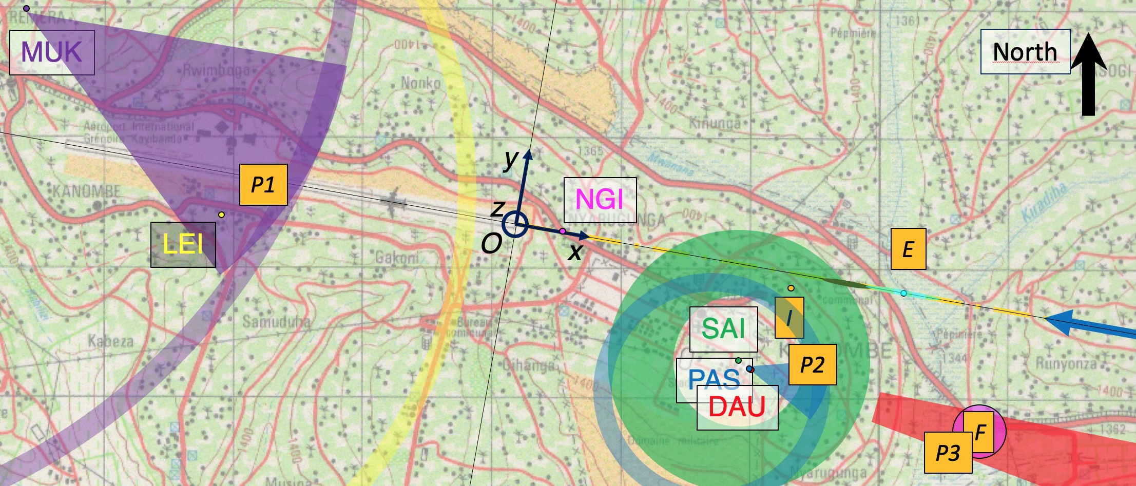
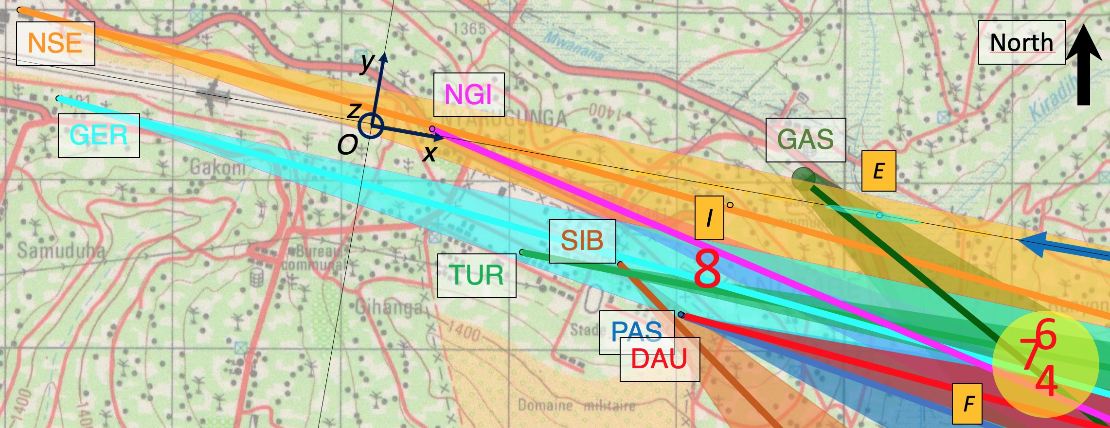
Kigali international Airport (IATA code: KGL; ICAO code: HRYR), sometimes referred to as Kanombe International Airport, and at that time called Grégoire Kayibanda international airport, is located in Kanombe, in the eastern suburbs of the Rwanda capital Kigali. The altitude of runway 28 threshold (east end) is m above sea level (4874 feet rcaa ). We take as the origin for both horizontal axes: axis , along the runway, oriented positively from West to East, and axis , perpendicular to the runway, oriented from South to North (Fig. 2).
According to the standard instrument approach procedure, an aircraft is expected to follow a well-defined trajectory in the vertical plane, at an angle from the horizontal, called the “glide”:
| (1) | |||||
| (2) |
The glide starts at 7.8 miles (Ref. cranfield p. 106) i.e. at m. The angular precision both in and in is a dot FSF ; CANSO , or rad. Hence we retain a linear precision on the value of both and .
I.2.3 Crash data
According to the few available recorded conversations between the pilots and the air trafic controllers bande , the crew announces at h21’27” that the aircraft is at 20 miles ( m) and 12000 ft altitude ( m). At 20h21’42”, it asks to make a direct approach into runway 28. The controller informs the aircraft (Ref. bande p. 11) that wind speed is 2 m/s (4 knots), temperature is 19∘C, ceiling and visibility are OK (“CAVOK”). More than two hours after sunset, it is dark night. All witnesses agree that the sky is clear and dark, without significant wind.
The aircraft begins to descend towards the airport. Most witnesses see two successive luminous lines coming from the South side of the aircraft; the first one comes close to the aircraft and misses it, the second one encounters the aircraft. Section IV discusses whether these are missile trajectories, and whether there are actually two of them.
After a few seconds, a big fireball is visible while the aircraft falls. Machine guns close to the airport shoot, including with tracer bullets. The aircraft hits the ground, bounces, and gets dislocated. It eventually hits (and punches through) the wall of the President’s residence, located close to the airport and (by mere coincidence) home of the aircraft owner. The combination of a spectacular fireball, the presence of two presidents, the crash in the aircraft owner’s residence, and the subsequent historical events, have all contributed to dramatise this crash. However, from the ballistic point of view, it is not as spectacular as explosive destructions of aircrafts at high altitude. Here the trajectory of the aircraft is normal almost until its end, the aircraft is already low and slow, it narrowly misses the runway threshold, and most of it is intact until it hits the ground.
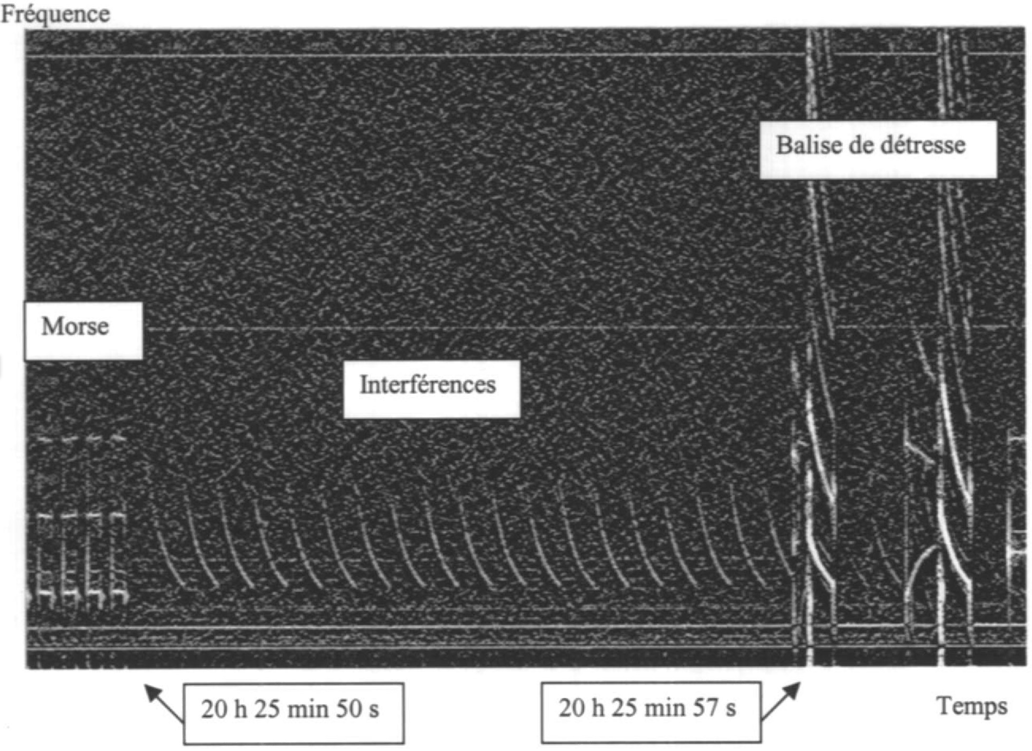
The airport detects a signal on the distress frequency during a 22 seconds time interval, between 20h25’50” and 20h26’12” (Ref. bande p. 10-13). The french aircraft crash expert assumes this is the time of the crash (Ref. bande p. 12). This does not distinguish between the time of the aircraft-missile encounter, , versus that of the aircraft impact on the ground, . In fact, the signal shape is too unusual to be attributed to any precise event. It superimposes two components of unknown origin (Fig. 1b). One is perceived during the whole 22 s interval; on Fig. 1b we can see 7 s of it, with 19 occurrences, hence we determine its period is s. It is termed “interferences” by the expert, although it is very regular and not noisy. The other one is perceived five times at regular intervals, at 20h25’57”, 20h25’59”, 20h26’02”, 20h26’05” and 20h26’07” (see details in Ref. bande p. 12), hence we determine its period is s. It is termed “distress beacon” by the expert, although it is periodic and limited in time, while in principle once activated (manually or due to a shock) a distress beacon is built to emit continuously and over days. We leave these signals open for interpretation and this indetermination does not affect what follows. Given the lack of information, we globally retain that and are probably close to each other, both being around 20h26’01” s, and we anticipate that their difference is of order of ten seconds (see Sections II.3, II.4).
We now turn to the positions of the aircraft-missile encounter, , and of the aircraft impact on the ground, (Fig. 2). In fact, the impact position is known. The impact trace was visible in 1994 as a 8 m circle, hence its position has been determined with a few meters precision by belgian investigators, as well as that of several aircraft fragments dispersed over a rectangle (Fig. 3a) of 145 m 20 m (Ref. belgian_investigators p. 5). Over the years, several fragments have been moved, degraded or removed, as described and mapped with laser range finding equipment in 2009 by UK experts (Ref. cranfield p. 8). In 2012, french investigators have combined their own geometrical measurements with the 1994 belgian report to determine within a few meters the impact position coordinates as m, m and m (Ref. oosterlinck p. 188, 192). Conversely, the encounter position is not known. Determining it is the subject of Section II.
(a)
(b)
II Encounter position
To determine the encounter position, it suffices to determine , then and will be readily found using the planned aircraft trajectory equation between and is Eqs. 1,2. Finding requires several steps, for instance to infer it from the impact position by reverse analysis of the aircraft trajectory between the encounter and the impact (Sections II.2 to II.4). This is possible if we first determine the aircraft longitudinal speed (hereafter “speed”, for short, and the dot indicates the time derivative) at the time of the encounter and impact (Section II.1).
II.1 Aircraft speed as a function of time
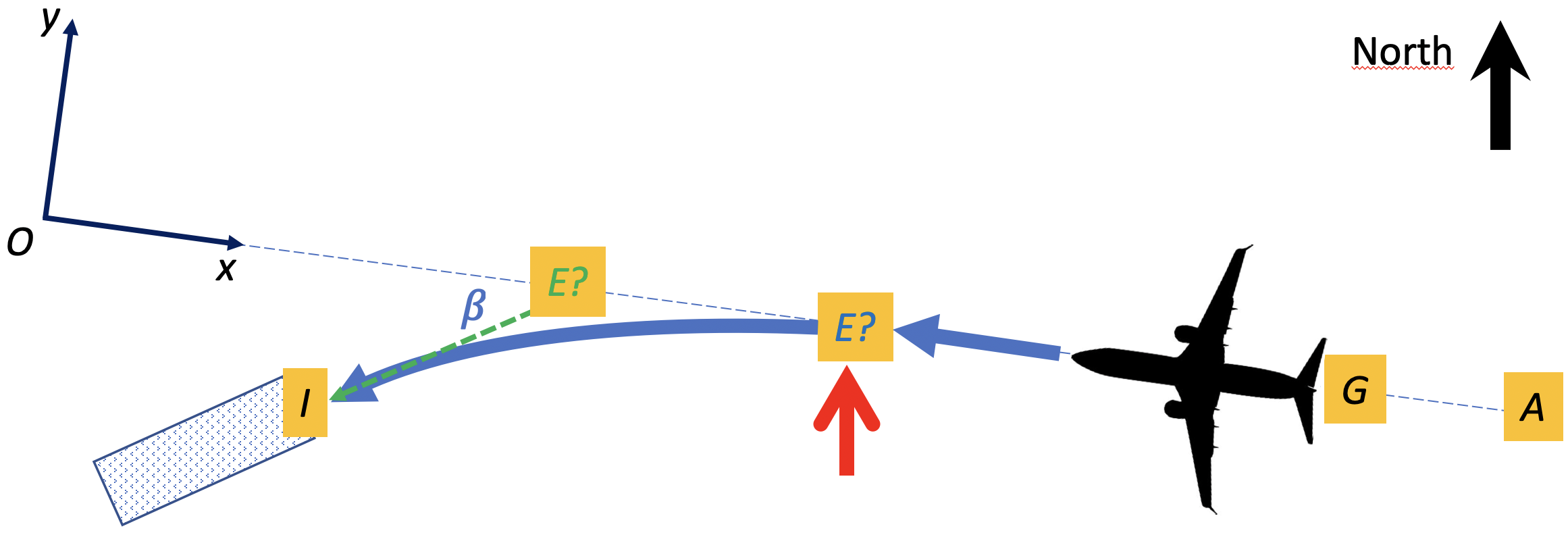
To determine the velocity vector as a function of time or position, it is first useful to determine whether the aircraft velocity vector is the same (Fig. 3) just after encounter ( as it is just before encounter (. A change in velocity vector could only arise from direct momentum transfer from the missile. The order of magnitude of the aircraft mass with fuel and passengers is larger than 104 kg (when empty, its mass is 9163 kg wp_falcon ). A missile considered here (Section IV.3) has a mass of order of at most 20 kg and a speed at most 1000 m/s oosterlinck . The mass ratio is at most 2 10-3, so the modification of the aircraft velocity vector could be at most of order of 2 m/s, oriented from South to North and bottom-up (red arrows on Fig. 3). The velocity vector change created by a missile, if non zero, would thus be tiny and in a direction opposed to the observed change in direction between encounter and impact.
A similar calculation could estimate the momentum transfer due to the metal fragments projected onto the aircraft by the warhead explosion. We lack detailed information, but we assume that several fragments of a few hundreds of grams are projected isotropically at a few times the sound velocity. If this is correct, again the momentum transfer to the aircraft does not significantly affect its velocity. In what follows, we ignore such effect and consider the velocity vector as unchanged at encounter.
Since the encounter with the missile only affects the aircraft velocity by a tiny amount and over a tiny portion of its trajectory, the above data (Section I.2.3) enable us to estimate approximately the average speed between crew announcement and impact (Fig. 3). The aircraft covers the distance m, with a precision around one mile (i.e. %) coming mostly from . If we take h26’01” s, the aircraft covers this distance in a time s (i.e. % precision). This means an average speed of m/s (247 kts) with a precision around 6%, assuming the imprecisions on distance and time are independent. This speed value is consistent with a Falcon 50 approach phase eurocontrol .
However, during the descent the aircraft is expected to decelerate, hence differs from the average speed. For simplicity we assume the deceleration is constant; note that hence . Then the speed and position as a function of time are
| (3) | |||||
| (4) |
where and are unknown. By eliminating (Eq. (3)) in Eq. (4), the speed profile as a function of distance is
| (5) |
A first constraint on the two unknown , is given by Eq. (4) using the known impact position and time . To obtain a second constraint we can assume that according to the Aircraft Performance Database eurocontrol the pilot was planning to land by arriving at m with a speed 67 m/s (130 kts), so that we can use Eq. (5). Eliminating from both constraints yields a quadratic equation on , with two negative solutions m/s or m/s. While the former value is irrealistic, and beyond the reach of a Falcon 50, the latter (353 kts) is consistent with aircraft data eurocontrol . It yields m/s2, which is positive as expected. Due to our assumption that is constant, and our other above assumptions, we roughly estimate the precision as m/s for speed and 30% for ( m/s2).
Eq. (5) then yields the speed at impact, m/s (141 kts). As a by-product of Eqs. (3-5) we also obtain that the aircraft intercepts the glide ( m) at time s, i.e. 20h23’56”, which as expected is posterior to the crew declaration (20h21’42”) of the intention to intercept it (Ref. bande p. 12). It then flies at m/s ( kts), a value which is consistent with aircraft dataeurocontrol but rather high (Ref. cranfield p. 106). This might mean that our constant deceleration hypothesis (Eq. (3)) should be slightly corrected, with more deceleration before intercepting the glide (between and ) and less deceleration later (between and ). Since we lack information we refrain from entering into these detailed calculations which do not significantly affect what follows.
II.2 Lateral deviation as a function of distance
To find , we now discuss where the trajectory after the encounter, projected on the horizontal plane, meets the trajectory before the encounter (Fig. 3a).
Qualitatively, since the ground impact is at m, it means that after the encounter the aircraft has laterally deviated from its planned trajectory towards the left, i.e. towards the South. This deviation could not be due to momentum transfer from missile (Section II.1).
In principle, the deviation could come from avoidance behaviour, i.e. if the pilot sees a first missile he could try to suddenly change the aircraft orientation in order to prevent a second missile to reach its target. But since the missile came from the South, i.e. the left side, the pilot might have chosen to steer towards the right, which does not explain the observed deviation towards the left.
More likely explanations which could have caused the observed deviation towards the left include: larger damages by the missile on the left engine than to the right one, and/or a progressive loss of lift on the left wing due to damages. In fact, belgian investigators infer from debris that only the left side of the plane has directly hit the ground, and observe that the left wing is much damaged while the right one is intact: both observations suggest the plane had rolled towards the left (Ref. belgian_investigators p. 3).
Quantitatively, combining the 1994 belgian report (Ref. belgian_investigators p. 5) with their own orientation measurements, french investigators have determined the orientation of the fragment dispersion main axis as from initial aircraft trajectory (Ref. oosterlinck p. 189), i.e. from axis. Based on the rectangle length 145 m and half-width 10 m (Section I.2.3) we estimate the precision of this angle determination to be . This suggests that when hitting the ground, the aircraft trajectory had deviated laterally by from the initial trajectory.
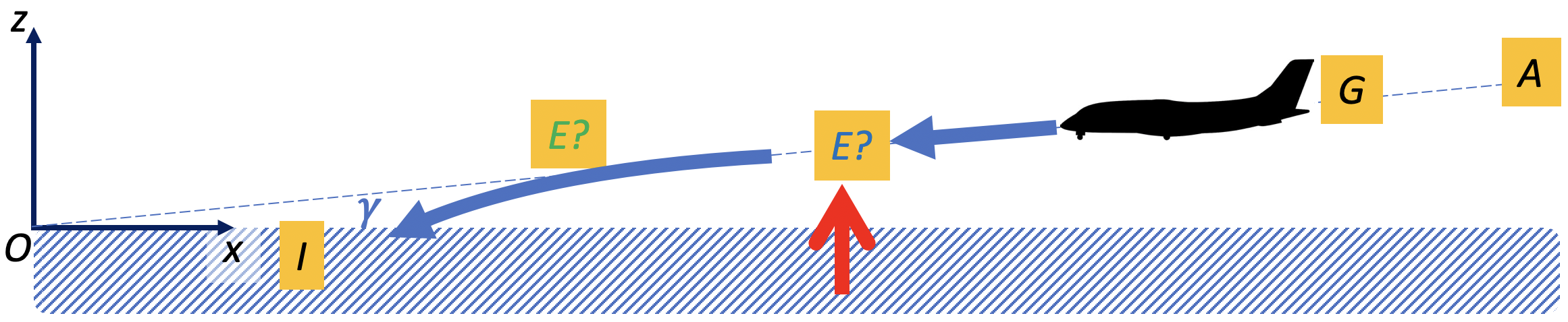
II.3 Free fall hypothesis and its inconsistencies
As a first approximation to determine the aircraft-missile encounter position , let us examine the unlikely but simplest possible trajectory after the encounter, that of a free fall. If the plane had suddenly deviated towards the left (e.g. due to avoidance behaviour) then undergone a free fall without any asymmetry between wings, its trajectory seen from the top, projected on the horizontal plane, would be a straight line (Fig. 3a), and seen from the side, in the vertical plane, would be a ballistic parabola (Fig. 3b) of vertical acceleration m/s2.
Extrapolating the fragment dispersion angle (Section II.2) would imply the encounter to be situated upstream of the ground impact at . Here m; m; , hence with a confidence range between 3.13 and 5.85; with a precision . Altogether, this would yield m and m (Fig. 2). Assuming that the precision on is m, and that the above confidence ranges are independent, we can determine the confidence range of ; it is unimportant for what follows, but it is an interesting exercise. With m and m we finally obtain for the range 2413 to 2739 m.
This would determine the fall duration and the speeds , . In fact, Eq. (2) would imply that at encounter, m and . Eq. (5) would yield that m/s and m/s. The vertical trajectory combined with the impact position would yield a quadratic equation to find , which positive solution would be s. The vertical speed at impact would be m/s.
This free fall scenario is unlikely for several reasons.
First, while this scenario is built on the correct lateral angle at impact , it incorrectly assumes that the aircraft trajectory acquires this direction immediately after encounter. Such sudden change of velocity vector at encounter is irrealistic, see Section II.1.
Second, between encounter and impact, the air flow around the intact right wing has probably remained laminar for some time, changing progressively rather than discontinuously. The aircraft did probably lose lift on the left wing due to damages, but kept enough lift to partially compensate its weight for a significant time. It means the aircraft could probably glide without stalling (Fig. 3b). In fact, pictures of the aircraft debris (Ref. oosterlinck p. 95) show that, as expected before landing and when the speed is lower than 98 m/s (190 kts manuel ) the pilot had already extended the high lift devices (so-called “flaps”). In this landing configuration, the speed at which a Falcon 50 stalls would typically have been of order 42 m/s (80 knots): the actual speed was above this limit.
Incidentally, we can suggest the following consistency check of our speed estimates. With a wingspan of 18.86 m wp_falcon , high lift devices a few tens of centimeters high, i.e. a cross-section S of order of 4 m2, air density of order of a kg/m3, and a drag coefficient difficult to estimate but of order of unity, we find the aerodynamic drag is roughly of order of N; during the fall, only the right motor functions, so the aerodynamic drag is only half compensated and the resulting force is of order of N. The aircraft mass being of order of kg, the longitudinal acceleration is of order of m/s2, yielding of order of m/s, compatible with Section II.1.
Third, this value of vertical speed, m/s, would imply a vertical impact angle , i.e. , which seems too high to explain the observed bouncing on the ground. A french military investigator observes soon after the crash that no debris is inserted in the ground, that there is no crater for the back part of the plane, and that the fore part has continued its longitudinal movement while creating a furrow; he infers that only a small part of the plane has been damaged by the missile, the plane has slowed down progressively, and was perfectly horizontal at the time of impact (Ref. bruguiere 8567, p. 12). Belgian investigators note that, although the ground is soft, the impact crater is shallow: they estimate the aircraft impact angle being at most 20∘ to the horizontal (Ref. belgian_investigators p. 3). UK experts agree with their estimation and add that aircraft debris would be expected to be found in the crater if the aircraft had adopted a more vertical descent into soft earth (Ref. cranfield p. 8).
We thus consider the free fall figures only as upper bounds for the vertical acceleration and vertical impact angle, and as lower bounds for , , and .
II.4 Estimates of encounter position
Beyond the lower bound determination of (Section II.3), we can suggest three determinations, one based on geometry, one based on witness indications, and one mixing both (Fig. 2).
(i) The first determination is based on the geometry of the horizontal trajectory, . If we assume the horizontal trajectory is a parabola starting at with a tangent parallel to axis (Fig. 3a), its equation is where is the curvature, and is unknown. The place of the ground impact is known, , and the tangent angle at the impact is known, . One finds that m. This is twice the value it would have in a free fall, and its confidence range is twice as large (see Section II.3). This yields m, with confidence range between 2666 and 3318 m.
(ii) The second determination is based on witness indications. Witnesses placed at the airport have a good visibility on the aircraft during its descent, but their axis of view is parallel to axis : their estimations of cannot be accurate and are widely spread (we find a distribution of values from 2000 m to 4200 m with a peak around 3100 m). Conversely, witnesses looking perpendicularly, e.g. placed at the North and looking South, can better determine . If we compile their indications, at the time of encounter the aircraft was flying over the Nyarugunga district of the Kanombe hill (see also Ref. mutsinzi p. 91), which we translate quantitatively into m.
(iii) The third determination uses both the aircraft speed we have found, and the fall duration . We do not know , since Section II.1 does not estimate it and Section II.3 only provides a lower bound of 6.2 s. We thus turn to indication NGI–2. According to it, the duration of the fall was not longer than 15 seconds. Assuming rather arbitrarily that s, using m/s (Section II.1), and since only varies by a few percents between and (Eq. (5)), we obtain m, with a precision around m.
In summary, the lower bound for is m, and the three determinations of are: (i) 2980 m (confidence range 2666 to 3318 m); (ii) m; and (iii) m. They are mutually compatible and we rather arbitrarily retain that m (Fig. 2).
This implies that m: the aircraft had almost finished its descent. The precision on is 300 m, that on is , and assuming they are independent yields a precision on of m. Hence in terms of absolute altitude, m; laterally, , with a precision of m. Eq. (5) yields the aircraft speed at encounter, m/s (150 kts), with a precision that we roughly estimate to be m/s. We also retain a vertical speed m/s. We can at last obtain a refined estimation of the fall duration s. We check it is compatible both with the lower bound 6.2 s (Section II.3) and the upper bound 15 s (NGI–2). This fall duration, for a parabolic vertical trajectory, would yield a vertical acceleration m/s2: in practice, this value is an average over the trajectory, since the vertical acceleration might vary due to the air drag on the aircraft. Neglecting this higher-order variations, we find a vertical speed at impact m/s (confidence range 30.2 to 44 m/s) and a vertical angle at impact (confidence range 21.4 to 30.1∘); the lateral angle at impact being , the lateral speed is of order of m/s. We thus confirm that the free fall figures (Section II.3) were upper bounds for the vertical acceleration and vertical impact angle, and lower bounds for , , and . We again refer the reader to Table 3 to keep track of these results.
III Launching position
Determining the position from where the missiles were launched from is a two-dimensional problem. It can be solved by combining witness indications of either distances (“trilateration”, Section III.1) or directions (“triangulation”, Section III.2).
III.1 Trilateration, using distances
In principle, witness indications regarding distances could be combined to determine (“trilateration”), and there are three such categories of indications which involve geometry or physics. In practice, these three categories are difficult to use quantitatively. In addition, some witness do not explain how they estimate distances.
First, sound amplitude could provide a distance information. One mission of the acoustics expert was to determine how the sound amplitude decreases with distance (Ref. oosterlinck p. 224). His conclusion is that the missile launching sound amplitude is perceived as 160 dB near the launching place, 133 dB at 80 m, 125 dB at 200 m, 104 dB at 2100 m (Ref. acoustic p. 18). Since no witness mentions any loud sound from missile launching (by comparison with the explosion sound coming from the aircraft, unanimously described as loud), and more generally witnesses insist on the difficulty to identify the causes of noises, one can reasonably exclude that a witness has been close to the launching place; we cannot be more quantitative.
Second, sound propagation too could in principle provide a distance information. Consider a witness placed at who sees the launching of a missile at , then later hears it, and measures the time lag between the view and the sound. Since the speed of sound is known (Ref. acoustic pp. 18-19), and recalling that there is no significant wind which could affect sound propagation (Section I.2.3), this could yield a precise estimate of the distance . Unfortunately, no single witness simultaneously fulfills all these conditions.
Third, three indications (PAS–1, LEI–1, MUK–1) mention a specific time sequence: they have heard a noise before they have seen the upper part of the missile trajectories. In principle, this could indirectly provide an useful information, namely an inequality between the distance between launching place and witness, and the distance between launching place and encounter: , where is the missile average speed. Equivalently, this inequality can be rewritten as:
| (6) |
where is the missile Mach number; its order of magnitude is 2 (Section IV.3). Thus lies close to . More quantitatively, since and are known, the set of points obeying Eq. (6) is a circle (Fig. 2) which includes , is not centered on , has a radius , and crosses the line at both sides of (at distances and ). In practice, this specific question of time sequence seems subject to variability in two witness memories. LEI is rather affirmative in his hearing right after the events in 1994 (LEI–1) but later, in his 2011 hearing, he has forgotten about it (LEI–2). In 2011 PAS is more affirmative (PAS–3) than in 1994 (PAS–1) but at the same time admits to have a less clear memory.
Finally, the following three indications provide distance estimates without explaining explicitly how they have obtained them (Fig. 2). SAI–1 mentions he is used to hear shootings and suggests a distance between 500 and 1000 m. DAU–1 provides a wide interval of distances, 1000 to 5000 m from his house, in the direction of Masaka. NGI–1 explicitly states the launching took place near Guttanit factory . At that time the factory was only a 80 m 40 m rectangle (Ref. bruguiere , 6017) centered at m and m (see below, Fig. 5). Given that this landmark size is less than 100 m and its distance to the closest other landmarks is more than 300 m, we rather arbitrarily attribute to this indication a confidence range of 200 m. Finally, many witnesses are assertive that it is Kanombe military camp or surroundings and exclude Masaka; conversely, many other witnesses are assertive that it is Masaka hill or surroundings and exclude Kanombe.
We retain that there are three pairs of distance indications (combined with direction indications whenever available), yielding three different results (Fig. 2). The intersection of LEI–1 and MUK–1 (“Pair 1”) would locate very imprecisely around the airport, west of . The intersection of SAI–1 and PAS–1 (“Pair 2”) would locate at Kanombe, south-west of . The intersection of DAU–1 and NGI–1 (“Pair 3”) would locate near Guttanit factory , south-east of . Overall, distance indications lack sources, precision, reproducibility and consistency.
III.2 Triangulation, using directions
From tens of visual indications (not shown), we have extracted a subset of 8 indications which obey all the following criteria. First, the witness position should be clearly known. Second, the direction details (whether by words, gesture or drawing) are known with enough precision to be used quantitatively. Third, the indication should unambiguously point at the launching , without confusion with encounter or impact . The third criterium happens to exclude all witnesses who place near , i.e. at the fence of the President’s residence; this creates a negative bias against this point. We have represented these 8 indications on a map (Fig. 4). We have attributed a direction precision of to four of them, DAU–2, NGI–3, NSE–1, TUR–1, and to the four others, GAS–1, GER–1, PAS–2, SIB–1.
Consider a witness number ( to 8), of position with coordinates , and who has seen in a direction . Together, and define a straight line, . The eight straight lines do not intersect at a single point; finding by triangulation is thus an overdetermined problem (Fig. 4). We suggest to use a minimization method based on the square distances to these lines. A point has a distance to , i.e. to its orthogonal projection on ; the square of is:
| (7) | |||||
To minimize the sum of these square distances means to look for the minimum of the r.m.s. distance:
| (8) |
Here we introduce the possibility of using weights to take into account the differences in their precisions. For instance, instead of equal weights , we can choose to assign a double weight to the four most precise witnesses with respect to the four less precise ones. Note that DAU–2 and PAS–2 are redundant: DAU and PAS were together inside the same house, estimated the direction based on both noise and light using a compass and landmarks such as trees and their window frame, then immediately recorded the direction on a map. But later, during hearings, DAU precisely reported the direction on a map, while PAS merely sketched it by hand, thus we attribute a better precision and higher weight to DAU–2 than to PAS–2.
Minimizing (Eq. (8)) amounts to solving the two equations , i.e.:
| (9) | |||||
| (10) |
The set of Eqs. (9,10), linear in and , has one and only one solution (except when all lines are parallel, which is not the case here).
At first sight, the result we find is suspicious. Weights 2 for the four precise witnesses and 1 for the four others yield m, m, with a r.m.s. distance m. This point (marked by a number “8” in Fig. 4), compatible with Pair 2 rather than Pair 3 of distance indications (Section III.1), is incompatible with five out of eight direction indications: DAU–2, GAS–1, PAS–2, SIB–1 and TUR–1.
In particular, the reconstitution of the landscape seen through the window of PAS’s house (Ref. oosterlinck p. 286), in which both PAS and DAU are located, shows that Masaka is visible right in the middle, while the point “8” would be much too far on the left to be visible through the window by these witnesses.
In such an overdetermined problem, it is advisable to use a robust method to deal with outliers Rousseeuw . No method is perfect; choosing the method has an impact on the result. One possibility is to minimize a norm other than the r.m.s. distance (Eq. (8)); for instance the average distance . For simplicity, we use here the Least Trimmed Squares Rousseeuw , which consists in removing one by one the data points in decreasing order of importance. To facilitate the intuitive understanding of the method, we manually implement it as follows.
If we consider SIB–1 as the most distant outlier and exclude it, then the resulting position and r.m.s. distance are more consistent and robust to changes in the weight. For instance, with all weights equal, m, m, while with double weight for the most precise ones we find m, m. The r.m.s. distance is around 212 m in both cases. This point is compatible with the observations of all 7 out of 7 indications (Fig. 4). Some indications have less importance; for instance, the witnesses placed at or near the airport see both Kanombe military camp and Masaka in the same direction, thus their direction indications (GER–1, NSE–1) do not discriminate. Removing one by one such indications does not significantly affect the results, which are dominated by the crossing point between DAU–2, and GAS–1 (Fig. 4). More generally, by testing various weight combinations, we aggregate the results for the launching position under the values m, m, with a r.m.s. residual of m. Combining the precision on and the r.m.s. residual results in a confidence range of roughly 300 m (Fig. 4). This is compatible with Pair 3 of distance indications (Section III.1).
IV Missiles
We now examine indications regarding the missile themselves: their launchers (Section IV.1), trajectories (Section IV.2) and type (Section IV.3).
Let us first remark that their number is not certain. Most ocular witnesses have seen two trajectories, then later a fire ball. Most auditive witnesses have heard two detonations, and later a louder detonation. The time interval values have a broad distribution, from a fraction of second to many seconds, with a peak around two seconds. Some other witnesses indicate they have seen or heard only one missile. Conversely, some hesitate between two and three missiles, some indicate they were three missiles, while one mentions a flare followed by two missiles. In summary we can write the number of missiles to be . This imprecision does not affect the other Sections, since there is a consensus on the most important point: there is one and only one successful missile.
IV.1 Missile launchers
A missile launcher is a tube which contains the missile before and during the launching. In normal circumstances, after launching the missile the team packs and removes most accessories, including the launcher. However, here, several witnesses mention that two missile launchers have been found. There is no consensus on the existence of these launchers, their number (which is 1 or 3 according to some witnesses), or the alleged finding date (Ref. mutsinzi p. 153-155). While we cannot address these points, we can at least check whether the indications regarding the alleged launcher positions are mutually consistent. We can also check whether these indications are consistent with launching positions independently determined (Section III), and up to which precision.
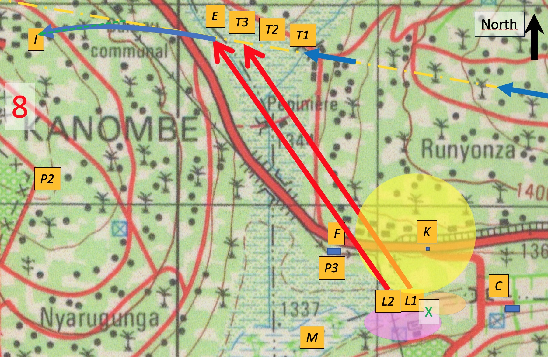
We use a detailed map at scale 1/2500 established by french experts (Ref. oosterlinck p. 60). Witnesses broadly agree on the finding place, designated using as landmarks either the “Km 19” crossing, “the Farm”, or the Masaka valley (Fig. 5). The Km 19, noted , is the crossing located at m, m, m. The Farm, a dairy cattle farming centre also called “Masaka farm” or “Centre d’élevage de bovins laitiers (CEBOL)”, noted , is at m, m, m. The Masaka valley stretches between these two landmarks, at m. One indication mentions the launchers have been found near Guttanit factory, (NGI–4).
Two indications are more specific (Fig. 5). One is a map of the place where launchers are supposed to have been found, drawn just south of the Guttanit factory (Ref. bruguiere , 8124); from this map we infer m, m. Rwandan investigators (Ref. mutsinzi p. 154, 156, 157), while doubting the finding is real, mention it would have been located “in the marsh”, at 300 m from Km 19 and 300 m too from the Farm. From this indication, we infer two positions (east and west of the line), only the west one being near the marsh: it is located at m, m. Together, these indications would suggest that the missile launchers have been found around m, m (green cross on Fig. 5). This is on dry land, not marsh, and corresponds to m.
In summary, the missile launcher indications are mutually consistent. They are also consistent with two out of six witness distance indications (Pair 3, Section III.1), consistent with the consensus of seven out of eight witness direction indications (yellow circle, Section III.2), and more precise than the latter consensus. Taking into account all these points, in what follows we retain as a likely launching position the point with coordinates m, m, m.
(a) (b) (c)
| Indication | |||
|---|---|---|---|
| DAU–3 | 60∘ | (45.5∘; 51.2∘; 55.1∘) | |
| MOR–1 | 70∘ | (02.7∘; 27.7∘; 44.6∘) | |
| MUT–1 | 45∘ | (26.6∘; 32.7∘; 37.5∘) | |
| SIB–2 | 43∘ | (26.9∘; 32.5∘; 36.7∘) |
IV.2 Missile trajectory
We now examine the missile trajectory length, orientation and curvature which, as we discuss below (Section IV.3), may have an influence on the missile type determination. Using three-dimensional geometry, we discuss separately the trajectory in its vertical plane, as viewed by the witnesses, versus in the horizontal plane, as would have been viewed from the sky.
From the estimates of missile launching place (Section IV.1) and of encounter position (Section II.4), we infer that the trajectory endpoint coordinate differences are of order of m. Hence the missile trajectory has a length of order of m, an angle (rounded to the degree) within the horizontal plane with respect to axis of (red arrows on Fig. 5), and an angle (averaged over the whole trajectory) with respect to the horizontal plane of .
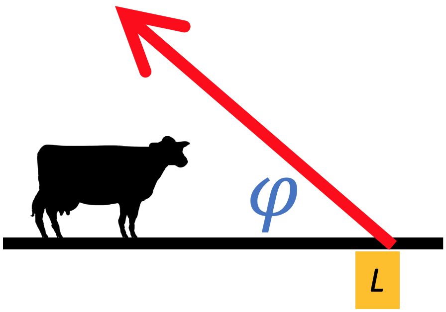
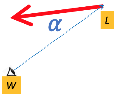
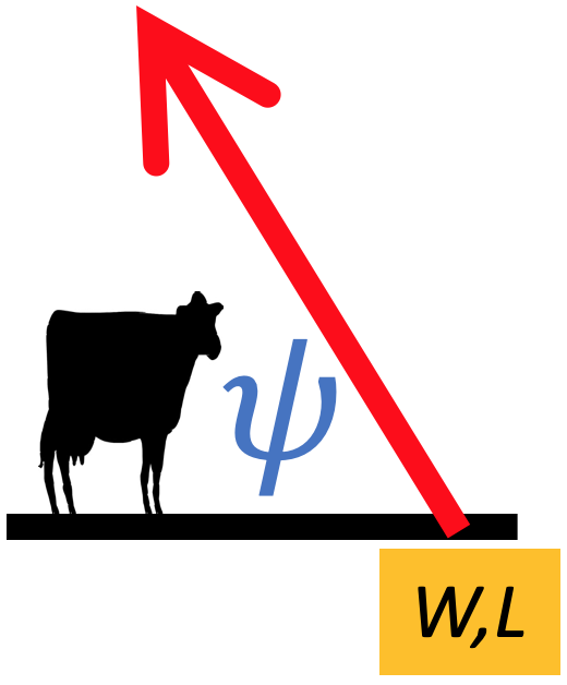
Independently, four witnesses indicate a value for the initial angle, , between the trajectory and the horizontal plane (Table 1). The actual launching angle with respect to the horizontal plane can be deduced from this perceived one, , using the three-dimensional trigonometric relation (Fig. 6):
| (11) |
The correction which leads from to is due to the angle between the line of view and the missile trajectory vertical plane ( is thus measured within the horizontal plane). This is an anamorphosis: the vertical component of the missile velocity vector is unchanged, while its horizontal component is affected by a factor . If the witness line of view is perpendicular to the missile trajectory, the witness correctly perceives . But in all other configurations, is larger than . At the extreme, a witness located in the same plane as the missile trajectory perceives it as vertical.
For the four witnesses, we determine using witness position , launching position and missile trajectory orientation with respect to axis . The imprecision on mainly comes from that of the missile trajectory orientation, itself mainly due to imprecision on . Since Eq. (11) is non-linear, we separately determine from the value of , then and from the confidence range of . Taking the average of the four values, and roughly estimating its precision, we retain .
Independently, we have checked (data no shown) the compatibility between the sign of and the witness indications that they saw the missile ascending “from left to right” (e.g. MOR–1) or “from right to left”. With this position, we find no inconsistency.
Note that for alternative launching positions, such as placed at airport by Pair 1 or at Kanombe by Pair 2 (Section III.1), we can recalculate the corresponding values of ; we then find incompatibilities both in values of and in signs of (data not shown).
This initial launching angle, , and the average trajectory angle, , are compatible if and only if the angle decreases with time, i.e. the trajectory is curved in the vertical plane. This is confirmed by some witnesses, who depending on their position see this curvature more or less pronounced (we have not detected any inconsistency). The actual trajectory is thus longer than the value m determined from endpoints positions.
The other curvature, seen from the top within the horizontal plane, cannot be perceived by witnesses and has to be inferred from other information. The missile is guided by the aircraft position (Section IV.3), with or without a trajectory anticipation procedure. In both cases, since the missile average speed is of order of ten times the aircraft speed at encounter , the deviation is at most 20∘ over 1.5 km hence the radius of curvature would be at least of order of five km. The trajectory would barely be curved, and seen from the top the deviation with respect to the straight line would remain small (Fig. 5).
Assuming there are two missiles launched at two seconds intervals from the position we retain, the aircraft speed at encounter and the missile average speed determine the times and aircraft positions “” when the first missile was launched, “” when the second one was launched, and “” when the first missile passed close to the aircraft, respectively around 6, 4 and 2 seconds before . These points are drawn on Fig. 5, and for legibility we do not draw their confidence range, which is large: it cumulates the m imprecision on with that due to our assumptions which is difficult to estimate.
In summary, the indications regarding missile launching angle with horizontal plane are consistent together, as well as with the launching position suggested by two out of six witness distance indications (Pair 3, Section III.1), by the consensus of seven out of eight witness direction indications (yellow circle, Section III.2), and by missile launcher indications (Section IV.1).
IV.3 Missile type
Hundreds of surface-to-air weapons were marketed in 1994 (Ref. oosterlinck pp. 102-174). Finding arguments to discriminate between them is difficult.
These weapons belong to three classes: either non propelled (e.g. machine gun bullets), self propelled but not guided (rockets), or self propelled and guided by the aircraft’s infrared emissions (missiles). All three classes travel at least at 300 m/s over 2000 m distance and 1500 m height. An aircraft flying at 156 m height, 1540 m distance and 77.1 m/s is well within their possibilities. Projectile trajectories are luminous (SIN–1): this could be due either to missile flight motor exhaust (Ref. cranfield p. 18-19), or to tracer ammunitions. The observed trajectory curvature in the vertical plane excludes rockets; in principle it could be due either to gravity, for bullets, or to guiding, for missile. Finally, most witnesses, especially civilians, are unable to discriminate between these classes.
However, the trajectory shape provides an argument. If the projectile had been purely ballistic, gravity acceleration of 9.81 m/s2 would have affected the projectile speed by a few tens of m/s and its height by a few tens of meters, hence would have modestly bent projectile trajectory. The trajectory shape we have found, with initial launching angle , and average trajectory angle , indicates that there was guiding (see an example of missile trajectory curvature on the picture of Ref. raytheon ). This is confirmed by witnesses. Some of them mention they saw the trajectories turning and heading towards the plane (GER–2, KAM–1, SIN–1). Another indication (GER–3) favors missiles: this witness is able to distinguish missiles from tracer ammunitions, and says he has seen the latter just after the former encounters the aircraft (compare GER–2, GER–3).
In 1994, the most widespread missile types were Stinger produced in the USA, Strela/Igla/SA/SAM produced in the USSR/Russia, Mistral produced in France. For simplicity, we compare only the specifications of these three types as they were available in 1994. Due to lack of information, we do not detail their many different variants nor their copies developed in other countries (Ref. oosterlinck p. 108-109).
Missile characteristics such as minimal and maximal shooting distance, speed, or maximal angle with the horizontal plane, do not discriminate between these three types. It is normal for these missiles to be launched far from the horizontal and then bend towards the horizontal (see the trajectory orientations on the picture of Ref. raytheon ). E.g. for a Mistral the nominal launching range is up to 67∘ simbad . Also, the guiding is operational only above a minimal distance, which means they have a minimal operational range: 500 m for Mistral simbad , 1000 m for SAM (Ref. oosterlinck p. 319). This explains why the launching position was far from the aircraft trajectory; as opposed to a non-propelled weapon which would have performed a direct shot and could have been launched from a place closer to the aircraft trajectory. Finally, the UK experts have used energy dispersive X-ray spectroscopy (EDS) to analyze possible metal fragments both free standing and embedded recovered in 2009 from the debris, but this study was too incomplete to unambigously discriminate the missile type (Ref. cranfield p. 32, 108).
| Quantity | SAM | Stinger | Mistral |
|---|---|---|---|
| Propulsion duration | 2 s | 3.49 s | 2.6 s |
| Ref. cranfield p. 54 | Eq. (12) | Ref. mindef_mistral | |
| Propulsion length | 686 m | 1316 m | 1114 m |
| Eq. (15) | Eq. (14) | Eq. (15) | |
| Speed at end of propulsion | 686 m/s | 754 m/s | 857 m/s |
| Ref. cranfield p. 54 | Ref. oosterlinck p. 162-167 | Ref. mindef_mistral | |
| Propulsion acceleration | 343 m/s2 | 216 m/s2 | 330 m/s2 |
| Eq. (12) | Ref. fas_man p. 3 | Eq. (12) | |
| Non-propulsion length | m | (0 m; 224 m; 524 m) | m |
| Eq. (17) | Eq. (17) | Eq. (17) | |
| Non-propulsion duration | s | (0 s; 0.3 s; 0.69 s) | s |
| Eq. (16) | Eq. (16) | Eq. (16) | |
| Total duration | s | (3.39 s; 3.79; 4.18 s) | s |
| Eq. (18) | Eqs. (13,18) | Eq. (18) |
In principle, the trajectory length could yield useful indications. Several witness indications suggest there has been a continuous luminous line from ground to aircraft (e.g. SIB–3, SIN–1); the continuity of the luminous line has been claimed to be a marker of the missile type. French experts consider it as a characteristics of SAM (Ref. oosterlinck p. 321), while UK ones estimate that the SAM trajectory is visible only over the first 1000 m (Ref. cranfield p. 18-19); independently, a missile specialist suggests that Mistral trajectory is visible only during the first 2 s while SAM and Stinger trajectories are continuously visible ancel_nepassubir .
In order to examine quantitatively this point, we model the trajectory to obtain an order of magnitude for the length and duration of the visible and non visible trajectory phases. Since missile types have variants, we decline to enter into too many details. For instance, to protect the gunner from the flight motor flames, a launch motor ejects the missile at a few meters from the launcher tube before the flight motor ignition begins. This ejection distance is 4 m for SAM (Ref. oosterlinck p. 237), 9 m for Stinger (Ref. fas_man p. 3), 12 m for Mistral simbad . For simplicity, we neglect this brief ejection phase in what follows. We model the trajectory with only two phases. First, a propulsion phase at almost constant acceleration during which the missile speed increases from 0 to and the trajectory is clearly visible due to flames. Its duration and length are related by the parabola equations:
| (12) | |||||
| (13) | |||||
| (14) | |||||
| (15) |
Then a non-propulsion phase at constant speed during which the trajectory is less visible. Its duration and length obey:
| (16) |
The total missile trajectory has duration and length :
| (17) | |||||
| (18) |
Using the data we collect, we can fill Table 2.
Within the above hypotheses, the total trajectory duration is slightly larger than the propulsion phase, so the luminous trajectory appears almost continuous. More specifically, if the trajectory length is at the lower end of its confidence interval, the non-propulsion phase can even vanish for Stinger, so that in this case we use Eq. (18) to fill Table 2. In summary, Stinger is more likely to be associated with a continuous luminous trajectory, while for Mistral the non propulsion phase lasts at least 0.15 s (126 m), and for SAM 0.81 s (554 m).
As a side result, we obtain the total trajectory duration, which is: 3.25 s for SAM, 3.79 s for Stinger, 3.10 s for Mistral.
See the remarks on rounding and units in Sections I.1, 2. We present here excess digits; for legibility, asymmetric confidence ranges (e.g. for , Section II.4) have been symmetrized. Name Symbol Value Precision Section Source Aircraft before encounter Time at crew announcement 20h21’27” 1 s I.2.3 Ref. bande p. 11 Position at crew announcement 37 040 m 1 852 m I.2.3 Ref. bande p. 11 ””” 3 657 m 300 m I.2.3 Eq. (2) Velocity at crew announcement m/s 10 m/s II.1 Eqs (3-5) Average deceleration 0.397 m/s2 0.012 m/s2 II.1 Eqs (3-5) Glide slope angle in vertical plane 3∘ 0.01∘ 2 Ref. cranfield p. 106 Position at glide interception 14 446 m 185 m 2 Ref. cranfield p. 106 ”””” 0 m 125 m II Eq. (1) ”””” 750 m 125 m II Eq. (2) Time at glide interception 20h23’56” 10 s II.1 by-product of Eqs (3-5) Velocity at glide interception m/s 10 m/s II.1 by-product of Eqs (3-5) Missile before encounter Missile number 2 1 IV witnesses Launching position 4 000 m 100 m IV.1 witnesses with triangulation ” ” 130 m 30 m IV.1 witnesses with triangulation ” ” 1 334 m 2 m IV.1 Ref. oosterlinck p. 60 Launching angle in horizontal plane 130∘ 10∘ IV.2 geometry Launching angle in vertical plane 36∘ 10∘ IV.2 Eq. (11) Average angle in vertical plane 12∘ 3∘ IV.2 geometry Trajectory length 1 540 m 300 m IV.2 geometry Trajectory duration: if SAM 3.25 s 0.44 s IV.3 Table 2 ”” if Stinger ” 3.79 s 0.4 s IV.3 Table 2 ”” if Mistral ” 3.1 s 0.35 s IV.3 Table 2 Aircraft-missile encounter Position of encounter 3 000 m 300 m II.4 geometry and witnesses ””” 0 m 20 m II.4 Eq. (1) ””” 1 641 m 30 m II.4 Eq. (2) Aircraft velocity at encounter m/s 10 m/s II.4 Eq. (5) ”””” 0 m/s 0.5 m/s II.4 Eq. (1) ”””” m/s 0.5 m/s II.4 Eq. (2) Aircraft impact on ground Time of encounter and impact 20h26’01” 11 s I.2.3 Ref. bande p. 12, 13 Fall duration 11 s 2.5 s II.4 geometry and witness Fall vertical acceleration m/s2 1 m/s2 II.4 geometry and velocity Position at impact 2 160 m 20 m I.2.3 Ref. oosterlinck p. 188, 192 ””” m 20 m I.2.3 Ref. oosterlinck p. 188, 192 ””” 1 410 m 2 m I.2.3 Ref. oosterlinck p. 188, 192 Velocity at impact m/s 10 m/s II.1 Eq. (5) ””” -18.3 m/s 2.3 m/s II.4 geometry and velocity ””” 38 m/s 7 m/s II.4 geometry and velocity Angle at impact in vertical plane 26.2∘ 5∘ II.4 geometry ””” in horizontal plane 13.7∘ II.2 Ref. oosterlinck p. 189
V Conclusion
We now summarize our results (Section V.1), discuss our hypotheses in the light of other possible choices (Section V.2), and draw some lessons for pedagogical purposes (Section V.3).
V.1 Summary
In summary, the publicly available informations interpreted by our calculations make most consistent a launching position at the south-east of the encounter (Guttanit-Km 19-Cebol triangle); less consistent a position at south-west (Kanombe military camp and surroundings); and rather inconsistent a position at west (airport).
Based on the most likely launching position, we would obtain the following scenario (Fig. 5). Here we have eventually rounded the results to make them as legible as possible. For additional digits, confidence intervals and sources see Table 3. For axes and units see Section 2.
On April 6th, 1994, the night is dark and the sky is clear. At 20h21’27”, the Falcon 50 aircraft immatriculated 9XR-NN is at m, m, with a longitudinal speed 181.5 m/s (353 kts), and a deceleration 0.397 m/s2. At 20h24’, with a speed 122.5 m/s (238 kts) it intercepts the standard straight trajectory (the “glide”) with slope angle . At 20h26’, it has almost finished its descent, its high lift devices (so-called “flaps”) are extended, it is at m, m (i.e. 156 m remaining), and flies with a westwards speed 77.1 m/s (150 kts) and downwards speed m/s.
Two self-propelled guided missiles are shot from a point located at m, m, m, i.e. between the Guttanit factory, the “Km 19” crossing and the bottom of the Masaka valley, close to the marsh. Their type is Stinger, Strela/Igla/SA/SAM, Mistral, or a copy thereof. They are launched at 36∘ from horizontal, then bend towards a more horizontal trajectory (which average slope is 12∘).
They cover the 1540 m distance in barely more than 3 s. They arrive with horizontal orientation at 130∘ from axis, i.e. three-quarter back (50∘) of the aircraft. Their luminous trajectory would appear almost continuous if they were Stingers, slightly less so for Mistrals and even less for SAMs.
The aircraft glides during 11 s, rolling and yawing towards the left, losing lift due to damages, with a left wing reservoir in fire. Its impact on ground is at m, m, m, with a westwards speed 72.7 m/s (141 kts), an orientation deviated by 13.7∘ towards the left, a vertical acceleration -3.08 m/s2 (a third of the free fall), a downwards speed at impact m/s, and a vertical angle at impact .
V.2 Discussion of alternative hypotheses
The above results and precisions (Section V.1, Table 3) depend on several hypotheses and methodological choices. Hypotheses that can have strong impacts on results include: assuming the aircraft has followed the standard instrument approach procedure; neglecting variations of aircraft acceleration; simplifying the missile trajectory phases; or neglecting aircraft velocity vector changes at encounter with missile. Moreover, methodological choices that can have strong impacts on results include: discarding outliers; deciding between minimization versus inverse inference methods; neglecting variants of each missile type; or ignoring avoidance behaviour by the pilot. Such methodological choices can reflect personal biases, be implicit, be difficult to detect, and strongly affect the conclusions. In the present case, we have tried to make our choices as explicit as possible, to support them with arguments, and to minimize their effects, e.g. by keeping a maximum of data and discarding only obvious outliers. Alternative methodological choices may yield other conclusions, as shown as follows regarding aircraft trajectory, missile type, and especially launching site.
V.2.1 Aircraft trajectory
Rwandan investigators (quoted by Ref. cranfield p. 31) assume m (6000 ft) and m/s (150 kts). The french investigators assume m/s (120 kts), a change at the encounter in the aircraft trajectory angle in the horizontal plane, and a free fall of the aircraft after the encounter (Ref. oosterlinck p. 178, 189-193).
Conversely, our Section II.3 provides arguments for gliding during fall, with twice larger longitudinal and vertical distances to impact, twice longer fall duration, half of impact angle, third of vertical acceleration. In turn, these discrepancies slightly affect the determination of missile launching point and trajectory. Moreover, French experts envision that the pilot has had avoidance behaviours after having detected the first missile (Ref. oosterlinck p. 183, 316): he might have briefly modified the aircraft speed or orientation. Our Section II.2 shows that this is unlikely and anyway does not affect significantly our results.
V.2.2 Missile type
Rwandan investigators discuss in detail who could have possessed SAMs mutsinzi , briefly discuss also the possession of Mistrals (Ref. mutsinzi p. 134, 135, 143) and, quoting the Belgian investigators, mention an indirect witness indication that it could be Stingers (Ref. mutsinzi p. 84). Belgian investigators disregard Mistrals because “it would imply the complicity of authorities of a nation which owns or produces them” (Ref. belgian_investigators p. 2). UK experts have focused their material investigations on SAM (Ref. cranfield p. 32, 54, 108). French experts exclude Mistrals by classifying them either in the category of “too recent” missiles (Ref. oosterlinck p. 137), or instead in the category “too sophisticated” (Ref. oosterlinck p. 172). On our side, since Mistral version 1 was widely available in 1994 (Ref. oosterlinck p. 172; see also Refs. ancel_nepassubir ; wp_mistral ) we do not exclude it a priori, and consider it as likely as both other types.
V.2.3 Launching site
To determine the launching site, two different classes of methods are possible: open approach or closed list. We choose an open approach, i.e. we avoid any a priori hypothesis on the launching site: the list of indications is compiled, and the launching site is inferred by minimizing the global disagreement with the various indications, possibly weighted (see our Section III). The list of indications we use is subject to biases, for instance when we happen to reject indications placing at the fence of the President’s residence (Section III.1).
Conversely, experts have established (or have received) a closed list of possible sites, then analyzed the compatibility of each site with witness indications. This enables to perform calculations, predictions and deductions, then compare them to other witness indications; agreements and disagreements are then discussed one by one.
Rwandan investigators list 5 launching sites: 1 in Masaka and 4 in Kanombe, including the President’s residence (Ref. mutsinzi p. 158-165). They exclude Masaka based on a sound intensity argument and on MOR–1 (Ref. mutsinzi p. 159-160) because they interpret the angle as the angle seen from the top, in the horizontal plane, between the aircraft and missile trajectories (Ref. mutsinzi p. 62). This is probably a mistake since a witness placed far away cannot estimate this angle. We retain the interpretation of angle as the angle with the horizontal plane, as perceived by the witness (Fig. 6), which is a strong argument in favor of a more eastern launching site (Section IV.2).
UK experts have received from Rwandan investigators a list of 3 launching sites, all situated in Kanombe (Ref. cranfield p. 15). These UK experts do not add information. More precisely, they do not find contradictions (Ref. cranfield p. 16-30) and do not discriminate between these 3 launching sites (Ref. cranfield p. 32). French experts, as explicitly specified by their mission (Ref. oosterlinck p. 8), list 6 launching sites including both Kanombe and Masaka (Ref. oosterlinck p. 224-225). The mission of the acoustic expert specified (Ref. acoustic p. 2) that he should answer the following question: which witnesses could have first heard missile launching, then seen the end of missile trajectories? This has had a strong effect on the determination of launching point position. Facing the differences between the three sound-based indication pairs, french experts have attributed importance to Pair 2, explicitly excluded Pair 1, and ignored Pair 3. This would locate at Kanombe, south-west of . We note that this is compatible with the point (Fig. 4) but not with directions indicated by DAU–2, GAS–1, PAS–2, SIB–1, TUR–1. Compare with our results (Figs. 4, 5, Sections III.2, IV.1) which locate near Guttanit factory , south-east of : they are compatible with Pair 3 distance indications (Section III.1), seven out of eight witness direction indications (Section III.2), alleged missile launcher position (Section IV.1), and missile trajectory angle (Section IV.2).
V.3 Impact for teaching
Each section of this study provides at least one idea of exercise for students. In addition, the impact for teaching is far-reaching, for the following reasons.
The method developed here is in itself a subject to teach. The students can be encouraged to provide data, determine which ones are important to discriminate between alternative models, determine the fields of physics which can feed the reasoning, and prevent circular reasoning while inferring information from whatever existing data. The imprecision discussion can train the students critical mind, as well as teach methods (e.g. inference, outlier trimming, optimisation) routinely used in several fields of physics research (e.g. in multi-messenger astrophysics, in complex systems studies, or in particle physics jamesminuit ). They can learn how the precisions regarding data propagate to determine results precisions.
We emphasize the importance of distinguishing hypotheses and methodological choices, and making both explicit. Overall, if different choices regarding hypotheses are exposed clearly, students can compare factual arguments and make their own opinion. The mission given to the experts is determinant: if the premises are incorrect, even a correct scientific approach can yield incorrect results. Students can understand that knowledge is a dynamic process based on trial and errors and that it gets further enriched thanks to explanation, confrontation, and addition of new data.
Incidentally, students can understand the importance of counting seconds during the time interval between seeing and hearing an event, to obtain a reliable inference of its distance. This can be routinely trained with lightning and thunder to determine the position of a storm.
To conclude, we note that in a technical domain, scientific expertise is required to master vocabulary and concept specificities, extract data from disparate sources, interprete and translate them in an unified way, detect which information is missing, suggest explicit hypotheses to compensate, and reduce a difficult problem to a set of separately tractable questions. This makes the problem accessible to undergraduate students, so that method becomes more important than expertise, as we illustrate here. Finally, it demonstrates the importance and limits of scientific investigation during a judiciary process.
Acknowledgements.
We thank Jacques Morel and Aymeric Givord for maintaining and making accessible the source document database http://francegenocidetutsi.org, Guillaume Ancel for technical explanations about missiles, Institut Géographique National (IGN, Brussels) for providing us the 1988 Kigali map and allowing to reproduce it, colleagues from MSC laboratory for stimulating discussions and especially Caroline Derec for critical reading of the manuscript. We welcome feedback on possible mistakes; and in case some are found in the future, we provide details in Table 3 to ensure their traceability. For the purpose of Open Access, a CC-BY 4.0 public copyright licence <https://creativecommons.org/licenses/by/4.0> has been applied by the authors to the present document and will be applied to all subsequent versions up to the Author Accepted Manuscript arising from this submission.*
Appendix A Witnesses and sources
This Appendix lists the witness indications actually used and quoted in the present article, with their sources. Italics are quotations (translated in english by us, if needed).
For legibility, only the three first letters of the witness surname are used;
then each indication is numbered consecutively.
| Witness | Indication | Indication | Indication |
|---|---|---|---|
| code | code | source | details |
| DAU | DAU–1 | Ref. bruguiere 2569, p. 1 | “Maximal distance from our location 5 km, minimal distance very difficult to estimate of order of 1 km.” |
| DAU–2 | Ref. bruguiere 7968, p. 10 | Drawing direction of | |
| DAU–3 | Ref. bruguiere 7968, p. 3, 10 | Drawing angle trajectory with horizontal “They were going from left to right with an ascension angle of about , the second being more vertical.” | |
| GAS | GAS–1 | Ref. bruguiere 7156, p. 1, 8056, p. 4 | “I was in the runway axis and for me luminous points were coming from the direction of Masaka hill.” |
| GER | GER–1 | Ref. oosterlinck p. 183, 262; Ref. bruguiere 2955 | Launching point: zone of the Farm or of Kanombe camp (for this witness both directions are the same) |
| GER–2 | Ref. cranfield p. 16 | “It is while I saw that the point took the direction of the plane that I realised that it must be missile fire. […] The theory of the missile fire is reinforced while I saw a second luminous point, the same as the first coming from the same place, taking the direction of the plane.” | |
| GER–3 | Ref. cranfield p. 17 | “ “Directly after the moment the plane exploded, gunfire rang out. I could perceive […] a number of firearms’ shots, some of which were with tracer bullets.” | |
| KAM | KAM–1 | Ref. mutsinzi p. 55-56 | “The bullets went straight up vertically and curved towards the aeroplane.” |
| LEI | LEI–1 | Ref. bruguiere 2715 | “I heard two deflagrations at very short time interval and saw in the sky two luminous points, one following the other.” |
| LEI–2 | Ref. bruguiere 7991, p. 5 | “I don’t remember it. I remember the noise, that’s all.” | |
| MOR | MOR–1 | Ref. cranfield p. 23 | “I am keen on clarifying that from the place where I found myself, the origin of the two missiles came from the left to head towards the sky towards the right. The angle of the shot was more or less 70 degrees.” |
| MUK | MUK–1 | Ref. oosterlinck p. 87, 284; Ref. bruguiere 7280 p. 2, 3 | “We have heard a kind of deflagration. We went out on the terrace and I saw two kinds of rockets following one another, towards the sky.” |
| MUT | MUT–1 | Ref. oosterlinck p. 77 | He has seen a burning line, then after 4 or 5 seconds another yellow burning line following a 45∘ trajectory. |
| NGI | NGI–1 | Ref. bruguiere 7739, p. 13 | “It is not really Masaka. The origin is situated right near the factory. I was looking.” |
| NGI–2 | Ref. bruguiere 7739, p. 13 | “When the aircraft was hit, there was not an interval of fifteen seconds before he was already fallen on the ground.” | |
| NGI–3 | Ref. bruguiere 7924, p. 5, 8056, p. 3 | Precise direction of | |
| NGI–4 | Ref. bruguiere 7739, p. 13 | “We were told launchers were picked up near the factory; right where the missiles have been fired.” | |
| NSE | NSE–1 | Ref. bruguiere 7927, p. 2, 8056, p. 2 | Precise direction of |
| PAS | PAS–1 | Ref. bruguiere 2577 | “Then I first heard a whooshing noise and seen an orange moving light […] The noise was followed by two detonations […] I went out and saw a fire ball crashing on the President’s residence.” |
| PAS–2 | Ref. bruguiere 7983, p. 5, 6, 7, 11 | Drawing direction of “From our windows on the garden side, I was struck by the place from which the light was coming, with respect to the trees. […] Very quickly, with Daubresse, we took a compass and estimated the azimuth, at horizon, of the most probable emergence of the missile or missiles. It seemed to yield the direction of Masaka hill, which we checked afterwards on the maps.” Both noise and light came from same direction: “back of the garden, Nyabarongo valley, direction of Masaka”. | |
| PAS–3 | Ref. bruguiere 7983, p. 5, 6 | “I am certain that I first heard two shots and then later saw a moving light. […] The chronology of this sequence, whoosh - detonations - moving light - explosion, was very clear in my mind when I was heard in 1994, and it is no longer the case.” | |
| SAI | SAI–1 | Ref. bruguiere 7998, p. 6 | “In reference to my “catalogue” (since in my life I have heard quite a lot of shootings), I would say between 500 and 1000 m.” |
| SIB | SIB–1 | Ref. bruguiere 7977, p. 2, 3, 8056, p. 3, 4 | Precise direction of |
| SIB–2 | Ref. bruguiere 7977, p. 3, 5 | Gesture evoking an angle of 40∘ demonstration with a pen inclined at 45∘ | |
| SIB–3 | Ref. bruguiere 7977, p. 4 | “- Q: Were the lights continuous until the aircraft? - A: Yes […] I saw a fire line until the plane.” | |
| SIN | SIN–1 | Ref. cranfield p. 19 | “I see something like a flame rise and overtake the path of the plane. Immediately after, a second was launched and hit the plane in full flight […] the two missiles would leave the ground and head towards the plane.” |
| TUR | TUR–1 | Ref. bruguiere 7930, p. 2, 7969, p 2, 3, 8056, p. 3, 4 | Precise direction of |
References
-
(1)
Cross, R.,
“Forensic Physics 101: Falls from a height”,
Am. J. Phys. 76, 833-837 (2008),
<https://doi.org/10.1119/1.2919736> -
(2)
Sharma, M.,
“Fundamental Physics used in Forensics”,
Forensic Sci. Add.. Res.
2020, 5, FSAR.000606.2019,
<https://doi.org/10.31031/FSAR.2019.05.000606> -
(3)
Feder, T.,
“Physicists in forensics - From faulty products to murder, physicists help figure out what really happened”,
Phys. Today
62, 20-22 (2009),
<https://doi.org/10.1063/1.3099569> -
(4)
Pregliasco, R. G. and Martinez, E. N.,
“Gunshot Location Through Recorded Sound: A Preliminary Report”,
J. Forensic Sci. 47, 1309-1318, 2002,
<https://doi.org/10.1520/JFS15566J> -
(5)
International Organisation of Legal Metrology (OIML), Guide to the expression of uncertainty in measurement - Part 1: Introduction, 2023,
<https://www.oiml.org/en/files/pdf_g/g001-gum1-e23.pdf> -
(6)
Instruction concernant l’attentat du 6 avril 1994 à Kigali, Tribunal de Grande Instance de Paris, 15 February 2022 (in french),
<https://francegenocidetutsi.fr/fgtarchives.php> -
(7)
Smeets, P. and Paque, J.
Rapport d’enquête, Sinistre aérien du 06 avr 94 à Kigali - Falcon 50, Note Auditorat Militaire N∘ 02.02545W94/Cab 8,
1st August 1994 (partly in french and partly in dutch),
<https://francegenocidetutsi.fr/fgtarchives.php>, 7154. -
(8)
Plantin de Hugues, P.
Rapport d’expertise, Tribunal de Grande Instance de Paris,
10 April 2002 (in french),
<https://francegenocidetutsi.fr/fgtarchives.php>, 6036 -
(9)
Warden, M.C. and McClue, W.A.
Investigation into the crash of Dassault Falcon 50 registration number 9XR-NN on 6 April 1994 carrying former President Juvenal Habyarimana,
Defence Academy of the United Kingdom and Cranfield University,
27 February 2009
(exists in english and in french; page numbers here refer to the english version),
<https://francegenocidetutsi.fr/documents/cranfield-en.pdf> -
(10)
Mutsinzi, J. et al., Report of the Investigation into the Causes and Circumstances of and Responsibility for the Attack of 06/04/1994 against the Falcon 50 Rwandan Presidential Aeroplane, Registration Number 9XR-NN, Republic of Rwanda, 20 April 2009 (exists in three languages; page numbers here refer to the english version),
<http://mutsinzireport.com> -
(11)
Mutsinzi, J. et al.,
Video Analysis of Habyarimana Plane Crash, 11 January 2010,
<https://www.youtube.com/watch?v=0bRJbPL1d3Y> -
(12)
Oosterlinck, C.
et al.,
Rapport d’expertise. Destruction en vol du Falcon 50 Kigali (Rwanda), Tribunal de Grande Instance de Paris, 5 January 2012 (in french),
<http://francegenocidetutsi.org/rapport-balstique-attentat-contre-habyarimana-6-4-1994.pdf> -
(13)
Serre, J.-P. Rapport complémentaire en acoustique,
Tribunal de Grande Instance de Paris,
3 January 2012 (in french),
<https://francegenocidetutsi.fr/documents/RapportExpertAcoustiqueJanvier2012.pdf>
Annexes A to E,
<https://francegenocidetutsi.fr/documents/AnnexesRapportAcoustique05012012.pdf> -
(14)
Rwanda Civil Aviation Authority,
HRYR Aerodrom chart ICAO - Kigali, Rwanda, 25 January 2024,
<https://rac.co.rw/eAIP%20Rwanda/1ST%20EDITION_2024_01_25> -
(15)
Flight Safety Foundation Approach-and-landing Accident Reduction Tool Kit - Briefing Note 7.1 - Stabilized Approach, p. 134, table 1, point 8,
<https://flightsafety.org/wp-content/uploads/2016/09/alar_bn7-1stablizedappr.pdf> -
(16)
Civil Air Navigation Services Organisation (CANSO), Unstable Approaches ATC Considerations, Appendix A, p. 15,
<https://www.icao.int/safety/RunwaySafety/Documents/Unstable%20Approaches-ATC%20Considerations.pdf> -
(17)
Institut Géographique National de Belgique & Service de cartographie du Rwanda, Rwanda map, serie Z 721, sheet 17, scale 1/50 000,
based on 1974 aerial photographs, 1977-1982 updates and 1985 field surveys, edition 1988 (in french),
<https://ngi.be/fr/offre/geodonnees-numeriques/cartes-topographiques-standards/>
For an updated map, see Open Street Map, search “Kanombe”,
<https://www.openstreetmap.org> -
(18)
Dassault Falcon 50, wikipedia (in french),
<https://fr.wikipedia.org/wiki/Dassault_Falcon_50> -
(19)
Eurocontrol Aviation Learning Centre, Aircraft Performance Database (only indicative) - FA50 Dassault-Breguet T16,
<https://contentzone.eurocontrol.int/aircraftperformance/details.aspx?ICAO=FA50&ICAOFilter=FA50> -
(20)
Dassault Aviation, Falcon 50 - Airplane Flight Manual,
<https://www.avialogs.com/aircraft-d/dassault/item/2743-falcon-50-airplane-flight-manual> -
(21)
Rousseeuw, P. J. and Leroy, A. M., Robust Regression and Outlier Detection, Wiley (2005),
<https://doi:10.1002/0471725382> -
(22)
Raytheon, Stinger missile;
see picture by U.S. Army entitled: A Stinger missile is launched during a live-fire test at the U.S. Army White Sands Missile Range in New Mexico,
<https://www.rtx.com/raytheon/what-we-do/integrated-air-and-missile-defense/stinger-missile> -
(23)
Matra Défense, Simbad: Système Intégré Mistral Bi-munitions pour l’Autodéfense (in french),
<http://www.netmarine.net> (consulted August 17th, 2014; no longer online). -
(24)
Ancel, G., Rapport d’expertise sur l’assassinat du président Habyarimana, le 6 avril 1994, blog, 28 January 2018 (in french),
<https://nepassubir.fr/2018/01/28/> -
(25)
SIRPATerre, Poste de tir Mistral - caractéristiques techniques, Armée de terre, 2012 (in french),
<www.defense.gouv.fr/terre/.pdf> -
(26)
Federation of American Scientists - Military Analysis Network,
MCWP 3-25.10 - Chapter 2 - Stinger Weapon System,
<https://man.fas.org/dod-101/sys/land/docs/ch2.pdf> -
(27)
Mistral (missile), wikipedia,
<https://fr.wikipedia.org/wiki/Mistral_(missile)> (in french). -
(28)
James, F., MINUIT - Function Minimization and Error Analysis, Reference Manual, CERN Program Library Long Writeup D506, Version 94.1, CERN, Geneva, 1994,
<https://inspirehep.net/literature/1258343>