Skyrmionium Dynamics and Stability on One Dimensional Anisotropy Patterns
Abstract
We examine a skyrmionium driven over a periodic anisotropy pattern, which consists of disorder free regions and disordered regions. For small defect densities, the skyrmionium flows for an extended range of currents, and there is a critical current above which it transforms into a skyrmion. For increased amounts of quenched disorder, the current needed for the skyrmionium to transform into a skyrmion decreases, and there is a critical disorder density above which a moving skyrmionium is not stable. In the moving state, the skyrmionium to skyrmion transformation leads to a drop in the velocity and the onset of a finite skyrmion Hall angle. We also find a reentrance effect in which the pinned skyrmionium transforms into a skyrmion just above depinning, restabilizes into skyrmionium at larger drives, and becomes unstable again at large currents. We also show that adding a transverse shaking drive can increase the lifetime of a moving skyrmionium by reducing the effect of the pinning in the direction of the drive.
1 Introduction
Magnetic textures such as skyrmions, skyrmionium, and merons have been attracting growing attention in basic science since they represent a new class of particle like states that can have interesting static and dynamical behaviors in the presence of a driving force and quenched disorder [1, 2, 3, 4, 5, 6, 7]. They are also promising candidates for a number of applications for memory [8, 9, 10] and novel computing architectures [11, 12, 13]. For many of these applications, it is necessary to understand how stable these textures are against quenched disorder and driving forces [14, 15, 16, 17, 18]. Topological textures can be defined by their topological number , or how many times their spin degrees of freedom can be wrapped around a sphere. When this topological number is one, , the state is a skyrmion and can exhibit a skyrmion Hall angle when moving. It is also possible to have a texture that is called skyrmionium [19, 20, 21, 22, 23, 24, 25]. For applications, skyrmioniums have several advantages over skyrmions in that their skyrmion Hall angle is zero, making it possible for skyrmioniums to travel along narrow channels without being pushed to the channel edge and annihilated due to the skyrmion Hall effect [22, 24, 26]. Additionally, skyrmioniums move twice as fast as skyrmions [22, 24, 26]. Recent work indicates, however, that skyrmionium is less stable under an applied current, and it transforms into a skyrmion at higher drives [25, 26]. Skyrmioniums can also undergo strong distortions with small Gilbert damping [24]. An open question is how stable skyrmionium is when it is driven over quenched disorder, which may either arise naturally in a sample or be introduced deliberately through nanostructuring.
In this work, we consider atomistic simulations of a skyrmionium moving over a periodic quasi-one-dimensional array of high and low pinning regions, where we vary the density of defects and the driving force. For low defect densities, the skyrmionium can undergo stable motion over an extended range of drives, and we find a critical current above which the skyrmionium transforms into a skyrmion. As the defect density increases, the current at which the skyrmionium transitions into a skyrmion decreases. The transformation to a skyrmion results in a drop in the velocity as well as the appearance of a finite Hall angle. Above a critical disorder strength , a moving skyrmionium is never stable. There is also a large increase in the depinning threshold of the texture above . We observe a reentrant transition in which the skyrmionium breaks up into a skyrmion at drives just above depinning, restabilizes into a skyrmionium at intermediate drives, and becomes unstable again at higher drives. The reentrance is produced by a competition between the quenched disorder and the driving force, since the driving force can partially reduce the effectiveness of the pinning in the moving state. We also show that applying a transverse ac drive to skyrmionium moving over strong quenched disorder can increase the amount of time that the skyrmionium remains stable.
2 Methods
We use an atomistic model [27] to model an ultrathin ferromagnetic film. Our sample is of size 272 nm 45 nm with periodic boundary conditions along the and directions. We apply a magnetic field perpendicular to the sample along at zero temperature, K.
The ultrathin film is modeled as a square arrangement of atoms with a lattice constant nm. The first term on the right hand side is the exchange interaction with an exchange constant of between magnetic moments and . The second term is the interfacial Dzyaloshinskii–Moriya interaction, where is the Dzyaloshinskii–Moriya vector between magnetic moments and and is the unit distance vector between sites and . Here, indicates that the sum is performed only over the nearest neighbors of the th magnetic moment. The third term is the Zeeman interaction with an applied external magnetic field , where is the magnitude of the atomic magnetic moment, is the electron -factor, and J T-1 is the Bohr magneton. The fourth term is the sample anisotropy, with anisotropy strength , and the last term is the defect anisotropy with anisotropy strength . The defects are contained in the set , and are modeled as randomly located higher anisotropy lattice sites. Defects are placed only within periodic stripes in the sample, as illustrated in Fig 1. The long-range dipolar interaction acts as an anisotropy in ultrathin films (see Supplemental Material of Wang et al.[29]), and therefore the effect of including such an interaction is to shift the anisotropy values.
Here T-1 s-1 is the electron gyromagnetic ratio, is the effective magnetic field including all interactions from the Hamiltonian, is the phenomenological damping introduced by Gilbert, and the last term is the torque induced by the spin Hall effect, where is the current density, is the spin polarization, is the electron charge, and is the current direction.
We fix the magnetic field value in our simulations. The material parameters are meV, , , , and . For each simulation, the system is initialized with a skyrmionium in a clean region at the left edge of the sample, as shown in Fig 1. The numerical integration of Eq. 2 is performed using a fourth order Runge-Kutta method over 200 ns.
In Fig. 1, we show a system in which the skyrmionium has been initialized on the left side of the sample. Along the direction, the sample alternates between disorder free and pinned regions. In this work, we hold the total area of the pinned regions constant and vary the density of the defects in the pinned regions, giving a defect density , where is the total number of spins in the sample and is the total number of defected spin sites. For the system in Fig. 1, . The skyrmionium is initially placed in a clean region, and the applied current drives the skyrmionium in the positive direction.
3 Results
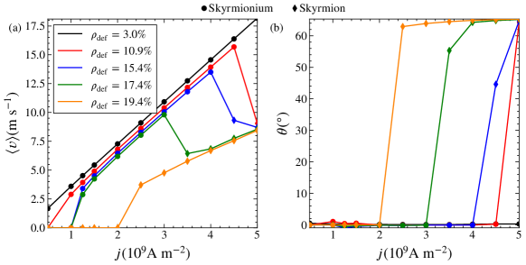
In Fig. 2, we plot the average velocity of the texture vs for the system in Fig. 1 at varied , , , , and . For , the velocity increases linearly with , and the texture remains a skyrmionium for drives all the way up to A m-2. There is a higher critical current (not shown) where the skyrmionium becomes unstable in the clean portion of the sample. For , , and , we find a finite depinning threshold that increases with increasing . At a critical driving force , there is a drop down in the velocity, and above this current the velocity resumes its linear increase with increasing from its new lower value. In Fig. 2(b), we plot the Hall angle of the texture versus . For currents smaller than , the Hall angle is zero, , as expected for skyrmionium. At , the Hall angle jumps up from zero to . The drop in the velocity is associated with a transition from a moving skyrmionium with and a zero Hall angle to a moving skyrmion with and a finite Hall angle. For , there is an extended range of current over which the skyrmionium remains pinned, and once the texture begins to move, it immediately transforms into a skyrmion, indicating that there is a critical defect density above which a moving skyrmionium is not stable.
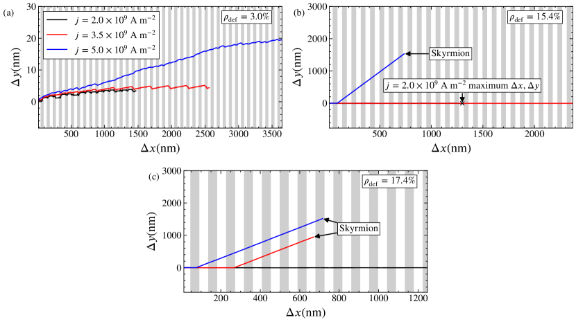
In Fig. 3, we show the trajectory of the textures, where we plot the displacements and over a fixed total time for different currents of A m-2, A m-2, and A m-2 at different defect densities. At in Fig. 3(a), the texture remains a skyrmionium for all of the drives we consider. This skyrmionium travels primarily along the direction, and only makes a small excursion into the direction for A m-2, where it moves nearly nm along the driving direction. In Fig. 3(b) at , the skyrmionium moves only along for A m-2 and A m-2, traveling a distance of nearly 2500 nm in the latter case. When A m-2, the skyrmionium transitions into a skyrmion after moving a distance of nm in the direction. After this, it moves with a finite Hall angle and translates approximately nm along the direction and nm along the direction. Here, the skyrmion moves more slowly and also at an angle to the drive compared to the skyrmionium. For in Fig. 3(c), at the lowest current of A m-2 the texture remains a skyrmionium and moves in the direction a total of nm. This indicates that as the density of the disorder increases, the distance the skyrmionium can travel during a fixed time decreases. For A m-2 and A m-2, the texture transitions into a skyrmion and moves at an angle to the drive. The rapidity of this transformation depends on the drive. For A m-2, the skyrmionium travels nm before transforming into a skyrmion, while for A m-2, it travels only nm. This indicates that there is a time dependent process that occurs during the skyrmionium transformation that is affected by the disorder density and the drive.
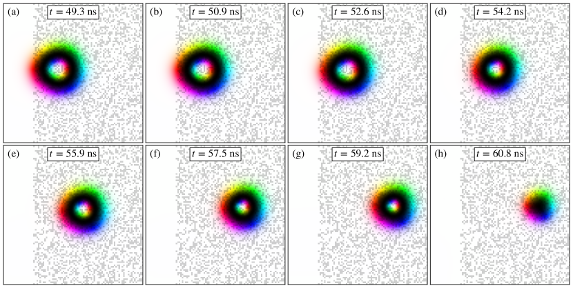
In Fig. 4, we illustrate the time dependent transformation of a skyrmionium into a skyrmion as it enters the pinned region for a system with A m-2 and . Here, the inner skyrmion shrinks until it collapses, similar to the behavior observed by Zhang et al.[33] upon increasing an external magnetic field. After the collapse, the skyrmion moves away from the collapse point with a finite skyrmion Hall angle.
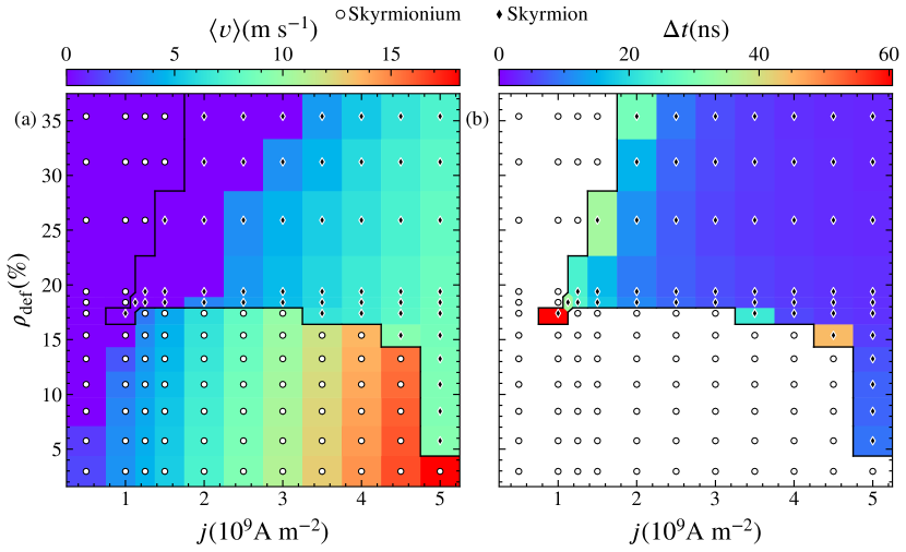
In Fig. 5(a), we plot a heat diagram of the average velocity as a function of versus as measured from velocity-force curves. We observe a pinned phase, moving skyrmionium, and moving skyrmions. The solid lines indicate the boundaries between the different states. For we find both pinned and moving skyrmionium states. The velocity in the moving skyrmionium regime decreases with increasing for fixed . In the same window of , there is a critical driving force above which the skyrmionium transforms into a skyrmion. This drive is accompanied by a drop in the velocity of the texture. The critical drive decreases with increasing . When , we find only pinned skyrmionium and moving skyrmion states since the skyrmionium transforms into a skyrmion upon depinning, indicating that there is a critical disorder strength above which a moving skyrmionium is unstable.
In Fig. 5(b) we show a heat map of the time required for the skyrmionium to transform into a skyrmion, , as a function of versus . Here, white regions indicate points at which the skyrmionium never transforms into a skyrmion. In general, the transformation time is longest near the depinning threshold. We find an interesting reentrance effect at , where the skyrmionium transforms into a skyrmion upon depinning at A m-2. This transformation appears in Fig. 5(a), and is also associated with the longest transient time in Fig. 5(b). For this same defect density, over the interval a moving skyrmionium is stable, while for A m-2 the skyrmionium becomes unstable again. The reentrance appears because there are two effects that can destabilize the skyrmionium. The first is the quenched disorder, which can induce a destabilizing roughness of the skyrmionium boundary, particularly near the depinning transition. The second is the current itself, which distorts the skyrmionium. From previous studies of driven particles moving over quenched disorder, it is known that the effective roughening produced by the quenched disorder can be diminished in the moving state at higher drives [15, 34], suggesting that the drive can actually reduce some of the roughness induced in the skyrmionium boundary by the pinning when the skyrmionium is in a moving state. If this reduction is greater than the roughness generated by the current itself, an applied drive can stabilize the moving skyrmionium over a certain range of quenched disorder densities and currents. Near the critical disorder density, there can be a window in which the drive decreases the distortion of the moving skyrmionium created by the pinning, and yet where the drive remains low enough that the current does not strongly distort the skyrmionium. The extent of this reentrance depends on the size scale of the disorder and other parameters.
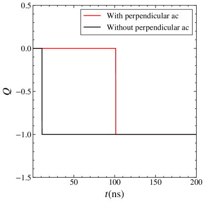
To test whether a transverse drive can reduce the effects of the quenched disorder, we applying a small transverse ac shaking drive to the dc driven skyrmionium. This causes the skyrmionium to move a small amount back and forth in the direction in addition to translating along . Above the critical disorder density, we find that the additional ac drive can increase the lifetime of the skyrmionium, as shown in Fig. 6 where we plot the topological charge versus time for a system with A m-2, , and a transverse ac drive of , where A m-2 and GHz. When only a dc drive is applied, the skyrmionium transforms to a skyrmion in less than ns. When transverse ac driving is added, the skyrmionium remains stable for ns, an increase of ten times compared to the purely dc driving situation. We have also considered other ac driving amplitudes and frequencies, and find that the stabilizing enhancement is the most prominent when A m-2, since overly large ac amplitude driving induces extra distortions that destabilize the skyrmionium instead of stabilizing it.
We expect the general features in the heat diagrams of Fig. 5 to remain robust for uniform disorder or other types of disorder patterns beyond the periodic array considered here, which would limit the possible regimes in which a moving skyrmionium can remain stable. We only considered a single skyrmionium; however, it is possible that a skyrmionium lattice might remain stable up to higher drives if the interactions between the textures are able to reduce the distortions that occur near the depinning transition. Previous work has shown that increasing the elastic interactions between neighboring particles can reduce the pinning threshold produced by quenched disorder [34]. It would also be interesting to study thermal effects. These could, on their own, destabilize the skyrmionium; however, thermal effects can also reduce the effectiveness of the quenched disorder, so it may be possible to observe additional reentrant phases at finite temperatures.
4 Summary
We have used atomistic simulations to investigate the driven dynamics of skyrmionium moving over a periodic disorder array for varied defect densities and drives. For low defect densities, the skyrmionium engages in stable motion for an extended range of currents. As the disorder density increases, there is a critical driving force above which the skyrmionium transforms into a skyrmion. This transition is accompanied by a sudden drop in the velocity at the critical driving force along with the onset of a finite skyrmion Hall angle. The value of decreases with increasing disorder density until a critical disorder density is reached above which a moving skyrmionium is unstable and the skyrmionium transitions to a skyrmion at the depinning transition. We map out a dynamic phase diagram as a function of disorder density versus current and find a pinned phase, a moving skyrmionium state, and a moving skyrmion state. Near the critical disorder strength, we find a reentrant behavior in which a drive just above depinning destabilizes the skyrmionium into a skyrmion, but an intermediate drive can stabilize the moving skyrmionium. At high drives, the moving skyrmionium again transitions into a moving skyrmion. This effect results when a drive in the reentrant window is able to reduce the roughening effect of the quenched disorder on the walls of the skyrmionium. We find that adding a transverse ac drive can enhance the stability of a moving skyrmionium since the ac drive acts as a shaking term that reduces the effect of the pinning on the texture. Our results indicate that while skyrmionium moves faster than a skyrmion in the presence of quenched disorder, the skyrmionium only remains stable over a limited range of current values and quenched disorder densities.
Acknowledgments
This work was supported by the US Department of Energy through the Los Alamos National Laboratory. Los Alamos National Laboratory is operated by Triad National Security, LLC, for the National Nuclear Security Administration of the U. S. Department of Energy (Contract No. 892333218NCA000001). J.C.B.S and N.P.V. acknowledge funding from Fundação de Amparo à Pesquisa do Estado de São Paulo - FAPESP (Grants J.C.B.S 2023/17545-1 and 2022/14053-8, N.P.V 2024/13248-5). We would like to thank FAPESP for providing the computational resources used in this work (Grant: 2024/02941-1).
References
References
- [1] Nagaosa N and Tokura Y 2013 Nature Nanotechnol. 8 899–911
- [2] Lin S Z, Reichhardt C, Batista C D and Saxena A 2013 Phys. Rev. B 87(21) 214419
- [3] Woo S, Litzius K, Krüger B, Im M Y, Caretta L, Richter K, Mann M, Krone A, Reeve R M, Weigand M, Agrawal P, Lemesh I, Mawass M A, Fischer P, Kläui M and Beach G S D 2016 Nature Mater. 15 501–506
- [4] Everschor-Sitte K, Masell J, Reeve R M and Klaüi M 2018 J. Appl. Phys. 124 240901
- [5] Göbel B, Mertig I and Tretiakov O A 2021 Phys. Rep. 895 1
- [6] Jani H, Lin J C, Chen J, Harrison J, Maccherozzi F, Schad J, Prakash S, Eom C B, Ariando A, Venkatesan T and Radaelli P G 2021 Nature (London) 590 74
- [7] Reichhardt C, Reichhardt C J O and Milosevic M 2022 Rev. Mod. Phys. 94 035005
- [8] Fert A, Cros V and Sampaio J 2013 Nature Nanotechnol. 8 152–156
- [9] Wang L, Liu C, Mehmood N, Han G, Wang Y, Xu X, Feng C, Hou Z, Peng Y, Gao X and Yu G 2019 ACS Appl. Mater. Interf. 11 12098–12104
- [10] Vakili H, Xu J W, Zhou W, Sakib M N, Morshed M G, Hartnett T, Quessab Y, Litzius K, Ma C T, Ganguly S, Stan M R, Balachandran P V, Beach G S D, Poon S J, Kent A D and Ghosh A W 2021 J. Appl. Phys. 130(7) 070908
- [11] Zázvorka J, Jakobs F, Heinze D, Keil N, Kromin S, Jaiswal S, Litzius K, Jakob G, Virnau P, Pinna D, Everschor-Sitte K, Rózsa L, Donges A, Nowak U and Kläui M 2019 Nature Nanotechnol. 14 658–661
- [12] Back C, Cros V, Ebert H, Everschor-Sitte K, Fert A, Garst M, Ma T, Mankovsky S, Monchesky T L, Mostovoy M, Nagaosa N, Parkin S S P, Pfleiderer C, Reyren N, Rosch A, Taguchi Y, Tokura Y, von Bergmann K and Zang J 2020 J. Phys. D 53 363001
- [13] Zhang H, Zhu D, Kang W, Zhang Y and Zhao W 2020 Phys. Rev. Applied 13(5) 054049
- [14] Iwasaki J, Mochizuki M and Nagaosa N 2013 Nature Commun. 4 1463
- [15] Reichhardt C, Ray D and Reichhardt C J O 2015 Phys. Rev. Lett. 114(21) 217202
- [16] Jiang W, Zhang X, Yu G, Zhang W, Wang X, Jungfleisch M B, Pearson J E, Cheng X, Heinonen O, Wang K L, Zhou Y, Hoffmann A and te Velthuis S G E 2017 Nature Phys. 13 162–169
- [17] Litzius K, Lemesh I, Krüger B, Bassirian P, Caretta L, Richter K, Büttner F, Sato K, Tretiakov O A, Förster J, Reeve R M, Weigand M, Bykova I, Stoll H, Schütz G, Beach G S D and Kläui M 2017 Nature Phys. 13 170–175
- [18] Juge R, Bairagi K, Rana K G, Vogel J, Sall M, Mailly D, Pham V T, Zhang Q, Sisodia N, Foerster M, Aballe L, Belmeguenai M, Roussigné Y, Auffret S, Buda-Prejbeanu L D, Gaudin G, Ravelosona D and Boulle O 2021 Nano Lett. 21(7) 2989–2996
- [19] Bogdanov A and Hubert A 1999 Journal of Magnetism and Magnetic Materials 195 182–192
- [20] Finazzi M, Savoini M, Khorsand A R, Tsukamoto A, Itoh A, Duò L, Kirilyuk A, Rasing T and Ezawa M 2013 Physical Review Letters 110 177205
- [21] Zhang X, Xia J, Zhou Y, Wang D, Liu X, Zhao W and Ezawa M 2016 Phys. Rev. B 94(9) 094420
- [22] Kolesnikov A G, Stebliy M E, Samardak A S and Ognev A V 2018 Sci. Rep. 8 16966
- [23] Zhang S, Kronast F, van der Laan G and Hesjedal T 2018 Nano Letters 18 1057–1063
- [24] Ishida Y and Kondo K 2020 Japanese Journal of Applied Physics 59 SGGI04
- [25] Xia J, Zhang X, Ezawa M, Tretiakov O A, Hou Z, Wang W, Zhao G, Liu X, Diep H T and Zhou Y 2020 Applied Physics Letters 117 012403
- [26] Souza J C B, Vizarim N P, Reichhardt C J O, Reichhardt C and Venegas P A 2024 arXiv:2412.02001
- [27] Evans R F L 2018 Atomistic Spin Dynamics Handbook of Materials Modeling: Applications: Current and Emerging Materials ed Andreoni W and Yip S (Springer International Publishing) pp 1–23
- [28] Iwasaki J, Mochizuki M and Nagaosa N 2013 Nature Nanotechnol. 8 742–747
- [29] Wang X S, Yuan H Y and Wang X R 2018 Communications Physics 1 31
- [30] Seki S and Mochizuki M 2016 Skyrmions in Magnetic Materials (Springer International Publishing)
- [31] Gilbert T L 2004 IEEE Trans. Mag. 40 3443–3449 ISSN 1941-0069
- [32] See supplemental material for animations showing the textures motion.
- [33] Zhang X, Xia J, Zhou Y, Wang D, Liu X, Zhao W and Ezawa M 2016 Phys. Rev. B 94 094420
- [34] Reichhardt C and Reichhardt C J O 2017 Phys. Rev. B 95(1) 014412